1
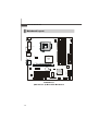
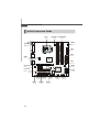
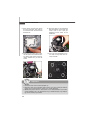
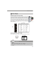
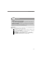
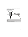
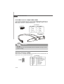
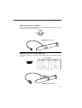
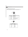
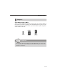
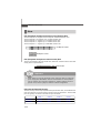
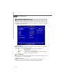
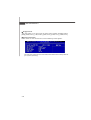
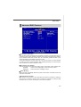
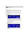
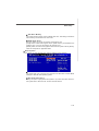
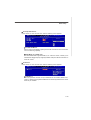
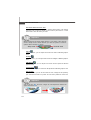
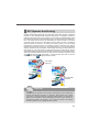
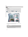
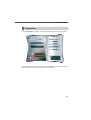
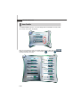
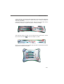
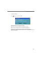
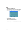
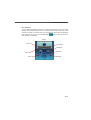
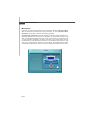
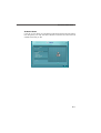
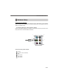
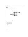
M S-7357 M ainboard
Fan Power Connectors: CPUFAN1, SYSFAN1
GND
+1 2V
SENSOR
CONTROL
The fan power connectors support system cooling fan with +12V. W hen connecting
the wire to the connectors, always note that the red wire is the positive and should
be connected to the +12V; the black wire is Ground and should be connected to GND.
If the mainboard has a System Hardware Monitor chipset on-board, you must use a
specially designed fan with speed sensor to take advantage of the CPU fan control.
CONTROL
SENSOR
+1 2V
GND
CPUFAN1
SYSFAN1
Important
1. Please refer to the recommended CPU fans at processor’s official website
or consult the vendors for proper CPU cooling fan.
2. Fan cooler set with 3 or 4 pins power connector are both available for
CPUFAN1.
3. CPUFAN1 supports fan control. You can setup it in H/W Monitor of BIOS
Setup. You can install Dual Core Center utility that will automatically
control the CPU fan speed according to the actual CPU temperature.
Chassis Intrusion Switch Connector: JCASE1
This connector connects to a 2-pin chassis switch. If the chassis is opened, the
switch will be short. The system will record this status and show a warning message on the screen. To clear the warning, you must enter the BIOS utility and clear the
record.
GND
CINTRU
2
1
JCASE1
CD-In Connector: JCD_IN1
This connector is provided for external audio input.
GND
L
R
JCD_IN1
2-14