1
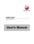
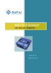
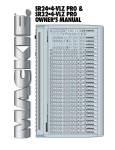
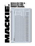
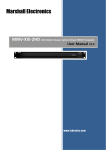
Operation Manual VT24HDview HighDefinition Monitors VIDRE LCD Monitors Operation Manual Page 2 of 44 VIDRE LCD Monitors Contents 1 General Rules........................................................................................................6 1.1 Safety Instructions.................................................................................................6 1.1.1 1.1.2 1.1.3 1.1.4 General rules ........................................................................................................6 Repairs ................................................................................................................6 Servicing...............................................................................................................6 Power Safety.........................................................................................................6 1.2 Trademarks...........................................................................................................6 1.2.1 1.2.2 Copyright..............................................................................................................6 Notice...................................................................................................................7 1.3 EMC .....................................................................................................................7 1.3.1 1.3.2 FCC Emission Information........................................................................................7 CE Declaration.......................................................................................................7 1.4 Care and Cleaning..................................................................................................7 1.5 Contacting Support.................................................................................................7 1.6 Limited Warranty....................................................................................................8 2 General Description................................................................................................9 2.1 Introduction...........................................................................................................9 2.1.1 2.1.2 2.1.3 High-Resolution LCD Monitors for multiple Applications...............................................9 Features................................................................................................................9 Application...........................................................................................................10 2.2 Model VT24HDView...............................................................................................10 2.2.1 2.2.2 2.2.3 2.2.4 2.2.5 2.2.6 Product Description...............................................................................................10 Features..............................................................................................................10 Network Port .......................................................................................................10 Restart Button......................................................................................................11 Default Button......................................................................................................11 Resolution Button.................................................................................................11 3 Supported Formats...............................................................................................12 3.1 Graphic Formats...................................................................................................12 3.1.1 3.1.2 3.1.3 3.1.4 Analog Graphic Formats........................................................................................12 Digital Graphic Formats.........................................................................................12 Other Graphic Formats..........................................................................................12 Supported Timings................................................................................................12 3.2 Video Formats......................................................................................................13 3.2.1 3.2.2 3.2.3 Analog Video Formats...........................................................................................13 Digital Video Formats SDI......................................................................................13 Digital Video Formats HDMI...................................................................................13 4 Dimensions and Mounting......................................................................................14 4.1 Desktop Mounting.................................................................................................14 4.1.1 4.1.2 Desktop Stand.....................................................................................................14 To adjust the monitor angle...................................................................................15 5 Operation Menu....................................................................................................16 5.1 Operation Keys.....................................................................................................16 Operation Manual Page 3 of 44 VIDRE LCD Monitors 5.2 Monitor OSD Menu Items.......................................................................................17 5.2.1 5.2.2 5.2.3 5.2.4 5.2.5 5.2.6 5.2.7 Information OSD..................................................................................................17 Menu Structure....................................................................................................17 Display Setting.....................................................................................................18 Picture Setting.....................................................................................................19 Picture Advanced Setting.......................................................................................20 PIP Setting..........................................................................................................20 System Setting.....................................................................................................21 6 Monitor Adjustments.............................................................................................23 6.1 Hot Keys..............................................................................................................23 6.1.1 6.1.2 6.1.3 Hot Key Brightness...............................................................................................23 Hot Key Contrast..................................................................................................23 Hot Key PIP..........................................................................................................23 6.2 How to adjust the screen resolution........................................................................23 7 Remote Control Software.......................................................................................25 7.1 Attention before use..............................................................................................25 7.1.1 7.1.2 Introduction of Web Control...................................................................................25 Function overview ................................................................................................25 7.2 Audio & Video.....................................................................................................25 7.2.1 7.2.2 7.2.3 7.2.4 7.2.5 Input Source........................................................................................................26 Output Resolution.................................................................................................26 Video Display Mode ..............................................................................................26 Color parameters..................................................................................................26 Audio to HDMI .....................................................................................................26 7.3 OSD parameters...................................................................................................27 7.3.1 7.3.2 7.3.3 7.3.4 7.3.5 7.3.6 7.3.7 7.3.8 Audio Meter Display .............................................................................................27 UMD...................................................................................................................27 Tally Display........................................................................................................28 AFD Display.........................................................................................................28 Safe Marker.........................................................................................................28 Input Format Display............................................................................................28 Waveform Display.................................................................................................28 OSD Layout management......................................................................................29 7.4 Alarm Settings.....................................................................................................30 7.4.1 7.4.2 Video Detection....................................................................................................30 Audio Detection....................................................................................................31 7.5 Status of Video and Audio .....................................................................................31 7.5.1 7.5.2 Video status ........................................................................................................31 Audio status ........................................................................................................31 7.6 User Configuration ...............................................................................................32 7.7 Network Configuration...........................................................................................33 7.7.1 7.7.2 7.7.3 7.7.4 Change IP address................................................................................................33 Change manager IP for SNMP Management..............................................................33 Items for SNMP ...................................................................................................33 Upgrade firmware of system .................................................................................34 8 I/O Panel and Connections.....................................................................................35 Operation Manual Page 4 of 44 VIDRE LCD Monitors 8.1 Input connections.................................................................................................35 8.1.1 8.1.2 Layout of the rear I/O panel...................................................................................35 Layout of the rear I/O panel with HDSDI..................................................................35 8.2 Connector Pin Assignment.....................................................................................35 8.2.1 8.2.2 8.2.3 8.2.4 8.2.5 8.2.6 8.2.7 8.2.8 8.2.9 8.2.10 D-Sub-15p VGA connector.....................................................................................35 DVI-D 24p connector.............................................................................................36 BNC 2p HDSDI connector.......................................................................................36 HDMI 18p HDMI connector.....................................................................................36 Mini-DIN 4p S-Video connector...............................................................................37 Mini-DIN 8p Component connector..........................................................................37 RCA 2p Composite connector.................................................................................37 RCA 2p Audio connector........................................................................................38 Dsub 9p Remote connector....................................................................................38 USB connector......................................................................................................38 9 Packing...............................................................................................................39 9.1 Shipping Box........................................................................................................39 10 Block-diagram......................................................................................................40 10.1 Electrical Diagram.................................................................................................40 11 Safety.................................................................................................................41 11.1 Safety standards and Compliance...........................................................................41 11.1.1 11.1.2 11.1.3 11.1.4 Standards............................................................................................................41 Insulation Resistance............................................................................................41 Insulation Dielectric Strength.................................................................................41 Environment........................................................................................................41 12 Frequently asked Questions...................................................................................42 12.1 Special Notice......................................................................................................42 12.2 Troubleshooting....................................................................................................42 12.2.1 Need more help?..................................................................................................43 Operation Manual Page 5 of 44 General Rules VIDRE LCD Monitors 1 General Rules 1.1 Safety Instructions 1.1.1 General rules Only use the device as directed in a dry atmosphere. Treat the VIDRE LCD Monitor with the same care as other studio devices. Please follow the advice in the following operators manual. Damages in transit If the device shows obvious damages from transit the shipper in question must be notified and the dealer must be informed. 1.1.2 Repairs The VIDRE LCD Monitors does not require any extra maintenance. There are no user serviceable parts at the device. Repairs should be sent to an authorized service partner. 1.1.3 Servicing Do not attempt to service this product yourself, as opening or removing covers may expose you to dangerous voltages or other risks. If any of the above mentioned misuse or other accident such as dropping or mishandling occurs, contact qualified service personnel for servicing. 1.1.4 Power Safety The AC plug isolates this equipment from the AC supply. The power supply cord serves as a power disconnect device for pluggable equipment. The socket outlet should be installed near the equipment and be easily accessible. This product should be operated from the type of power indicated on the marked label. If you are not sure of the type of power available, consult your dealer or local power company. 1.2 Trademarks VIDRE and the VIDRE logo are trademarks of PTV Professional TeleVision GmbH. GeFei, MIO and Gra-Vue logos are trademarks of Gefei Tech. Co. Ltd.All other trademarks are the property of their respective holders. 1.2.1 Copyright No part of this document may be reproduced, translated into another language, stored in a retrieval system, or transmitted, in any form or by any means, electronic or mechanical, including photocopying or recording, or otherwise without the express written permission of PTV Professional TeleVision GmbH. Technical changes are reserved. All brand and product names mentioned herein are used for identification purposes only, and are trademarks or registered trademarks of their respective holders. Information in this publication replaces all previously published information. PTV Professional TeleVision GmbH assumes no responsibility for errors or omissions. Neither is any liability assumed for damages resulting from the use of the information contained herein. Whenever it is likely that safe operation is impaired, the instrument must be made inoperative and secured against unintended operation. The appropriate service authority must then be informed. Copyright © PTV Professional TeleVision GmbH 2007-2013. All rights reserved. Operation Manual Page 6 of 44 General Rules VIDRE LCD Monitors 1.2.2 Notice All information in this manual is subject to change without notice. The information in this manual is published for informational use only . 1.3 EMC The EMC regulations are observed only under the following condition: • use high quality shielded cables at data inputs and outputs. 1.3.1 FCC Emission Information This equipment has been tested and found to comply with the limits for a Class A digital device, pursuant to Part 15 of the FCC Rules. These limits are designed to provide reasonable protection against harmful interference when the equipment is operated in a commercial environment. This equipment generates, uses and can radiate radio frequency energy and, if not installed and used in accordance with the instruction manual, may cause harmful interference to radio communications. Operation of this equipment in a residential area is likely to cause harmful interference in which case the user will be required to correct the interference at his own expense. Changes or modifications not expressly approved by PTV Professional TeleVision GmbH can effect emission compliance and could void the user’s authority to operate this equipment. 1.3.2 CE Declaration We, PTV Professional TeleVision GmbH, declare under our sole responsibility that the VIDRE LCD Monitors meets the intent of the following directives, standards and specifications: • 89/336/EEC Electromagnetic Compatibility • EN 50081-1 Emissions, EN 55022, EN 55103-1 • EN 50082-1 Immunity, EN 55024,EN 55103-2 1.4 Care and Cleaning Cleaning. Always unplug your monitor from the wall outlet before cleaning. Clean the LCD monitor surface with a lint-free, non-abrasive cloth. Avoid using any liquid, aerosol or glass cleaners. Slots and openings on the back or top of the cabinet are for ventilation. They must not be blocked or covered. Your monitor should never be placed near or over a radiator or heat source, or in a built-in installation unless proper ventilation is provided. Never push objects or spill liquid of any kind into this product. 1.5 Contacting Support For further information please contact your local dealer or contact PTV Professional TeleVision GmbH for sales or technical support. Use any of the following methods: PTV Professional TeleVision GmbH Kirchweg 62 B D-24558 Henstedt-Ulzburg tel +49 - 4193 - 997 80 fax +49 - 4193 - 997 820 sales email info @ vidre.de support email support @ vidre.de web www.vidre.de When calling for support, have all information on the product (serial number etc.) at hand Operation Manual Page 7 of 44 General Rules VIDRE LCD Monitors prior to calling. 1.6 Limited Warranty PTV Professional TeleVision GmbH warrants that this product will be free from defects in materials and workmanship for a period of twenty-four month from the date of purchase. If a product proves to be defective during this warranty period, PTV Professional TeleVision GmbH, at its option, will either repair the defective product without charge for parts and labor, or will provide a replacement in exchange for the defective product. In order to obtain service under this warranty, you the Customer, must notify PTV Professional TeleVision GmbH of the defect before the expiration of the warranty period and make suitable arrangements for the performance of service. The Customer shall be responsible for packaging and shipping the defective product to a designated service center nominated by PTV Professional TeleVision GmbH, with shipping charges prepaid. PTV Professional TeleVision GmbH shall pay for the return of the product to the Customer if the shipment is to a location within the country in which the PTV Professional TeleVision GmbH service center is located. Customer shall be responsible for paying all shipping charges, insurance, duties, taxes, and any other charges for products returned to any other locations. This warranty shall not apply to any defect, failure or damage caused by improper use or improper or inadequate maintenance and care. PTV Professional TeleVision GmbH shall not be obligated to furnish service under this warranty a) to repair damage resulting from attempts by personnel other than PTV Professional TeleVision GmbH representatives to install, repair or service the product, b) to repair damage resulting from improper use or connection to incompatible equipment, c) to repair any damage or malfunction caused by the use of non-PTV Professional TeleVision GmbH parts or supplies, or d) to service a product that has been modified or integrated with other products when the effect of such a modification or integration increases the time or difficulty of servicing the product. THIS WARRANTY IS GIVEN BY PTV Professional TeleVision GmbH IN LIEU OF ANY OTHER WARRANTIES, EXPRESS OR IMPLIED. PTV Professional TeleVision GmbH AND ITS VENDORS DISCLAIM ANY IMPLIED WARRANTIES OF MERCHANTABILITY OR FITNESS FOR A PARTICULAR PURPOSE. PTV Professional TeleVision GmbH’S RESPONSIBILITY TO REPAIR OR REPLACE DEFECTIVE PRODUCTS IS THE WHOLE AND EXCLUSIVE REMEDY PROVIDED TO THE CUSTOMER FOR ANY INDIRECT, SPECIAL, INCIDENTAL OR CONSEQUENTIAL DAMAGES IRRESPECTIVE OF WHETHER AJA VIDEO OR THE VENDOR HAS ADVANCE NOTICE OF THE POSSIBILITY OF SUCH DAMAGES. Operation Manual Page 8 of 44 General Description VIDRE LCD Monitors 2 General Description 2.1 Introduction 2.1.1 High-Resolution LCD Monitors for multiple Applications The VIDRE V-series Monitors were designed as compact and universal monitors at a low budget price. They are usable to display images in studios, control rooms or OB-vans, but for presentation or signage applications at airports, museums or exhibitions, industrial control systems and surveillance monitoring either. Equipped with his high resolution displays VIDRE monitors stands for a crisp and detailed image reproduction at a high and homogen brightness all over the screen. VIDRE monitors offering a state-of-the-art digital input, are fully equipped and supporting most common signal standards. They are a reliable tool to proof image quality in studios, digital signage or IT systems. For video applications models equipped with SD/HD-SDI inputs are available. VIDRE LCD Monotors contains TFT Liquid Crystal Displays(TFT LCD) with multiple CCFL Backlight units. This displays supports 1920 x 1080 HDTV format and can display true 16.7M colors (8-bit/color). 2.1.2 Features Main features for the VIDRE LCD monitors are • High brightness • High contrast ratio • Fast response time ( Gray to Gray 6.5 ms) • High color saturation • Max resolution 1920 x 1080 (HDTV format) • Ultra wide viewing angle:176(H)/ 176(V) Super MVA technology • Support PIP/PAP function Operation Manual Page 9 of 44 General Description VIDRE LCD Monitors • Configurable ambient light sensor • VGA/DVI input support Video sync - 1080p • OSD menu controls by Remote controller, OSD button and RS232C controller The Display operation Mode is transmissive at normally black. The surface treatment has an Anti-Glare coating (Haze 25%) and Hard coating (3H) 2.1.3 Application Main applications for the VIDRE LCD monitors are • Video Production Applications • Public Display Application • Home Theater Application • MFM Application • MultiViewer Application • Signal Control Monitor 2.2 Model VT24HDView 2.2.1 Product Description Based on VIDRE V-sereies, VT24HDview is a high-quality monitor equipped with an 3G/HD/SDSDI input and signal processor to display digital video and audio signals. VT24HDview can be controlled by Ethernet network via IE browser, which is convenient to configure the display parameters. The device provides audio and video detection, such as signal loss, signal freeze, audio silence and so on. The text of UMD program can be edited freely. And it supports SNMP, which is easy to manage the device. Although the signal processor adopts DVI output interface, the HDMI signal can be obtained by using a DVI to HDMI adapter or cable. In HDMI mode, the HD/SD audio are embedded into HDMI signal. 2.2.2 Features Basic features of the SDI signal processor are: • Automatic input detection of 525i60, 625i50, 720p, 1080i and 1080p format of SDI signal • Various output resolutions up to 1920x1080px60 • In HDMI mode, the HD/SD audio are embedded into HDMI signal • Audio and video monitoring and alarm, such as signal loss, signal freeze, audio silence • Display program UMD and 8 channels audio, and adjust transparency of them freely • Various waveforms, such as illumination waveform, PbPr waveform, audio waveform, etc • Build-in web server to control the device with user-friendly interface • Adjust luminance, saturation, contrast and de-noise freely • Provide on-screen display: input formats, AFD and safe marker • Supports SNMP 2.2.3 Network Port The signal processor is equipped with a RJ45 interface with 10/100/1000M auto-detection. The default IP address is 192.168.1.76. The built-in web server operates as remote control interface. Operation Manual Page 10 of 44 General Description VIDRE LCD Monitors 2.2.4 Restart Button To restart the SDI signal processor use a push pin to press the button named RESTART. The function of the button equals to turn off. Probably around 5 seconds the unit restarts using the last settings. 2.2.5 Default Button To set the SDI signal processor back to default modes use a push pin to press the button named DEFAULT/RESOLUTION for several seconds until the DVI output disappears. The parameters at the internal web page will be restored to default settings, including the IP address and user password. The default IP address is 192.168.1.76, and the default password is 000000 (six zeros). 2.2.6 Resolution Button To select different display resolution of the signal processor use a push pin to press the button named DEFAULT/RESOLUTION shortly. The output resolution toggles between mode 1280p60, 1080p60 and AUTO. Operation Manual Page 11 of 44 Supported Formats VIDRE LCD Monitors 3 Supported Formats 3.1 Graphic Formats 3.1.1 Analog Graphic Formats The VIDRE monitors supports following formats at their analog graphic inputs. The table below list the accepted formats. Format Resolution Frequencies Format Resolution Frequencies VGA 640 x 480 56 - 75 Hz WVGA 800 x 480 56 - 75 Hz SVGA 800 x 600 56 - 75 Hz WSVGA 1024 x 600 56 - 75 Hz XGA 1024 x 768 56 - 75 Hz WXGA 1360 x 768 56 - 75 Hz SXGA 1280 x 1024 56 - 75 Hz SXGA 1152 x 864 56 - 75 Hz UXGA 1600 x 1200 56 - 75 Hz WUXGA 1920 x 1200 56 - 75 Hz MAC I 640 x 480 56 - 75 Hz MAC II 832 x 624 56 - 75 Hz MAC III 1024 x 768 56 - 75 Hz 3.1.2 Digital Graphic Formats The VIDRE monitors supports following formats at their digital graphic inputs. The table below list the accepted formats. Format Resolution Frequencies Format Resolution Frequencies VGA 640 x 480 56 - 75 Hz WVGA 800 x 480 56 - 75 Hz SVGA 800 x 600 56 - 75 Hz WSVGA 1024 x 600 56 - 75 Hz XGA 1024 x 768 56 - 75 Hz WXGA 1280 x 768 56 - 75 Hz SXGA 1280 x 1024 56 - 75 Hz WSXGA 1600 x 1050 56 - 75 Hz UXGA 1600 x 1200 56 - 75 Hz WUXGA 1920 x 1200 56 - 75 Hz 3.1.3 Other Graphic Formats Some VIDRE monitors supports following elder graphic formats at their analog graphic inputs. The table below list the accepted formats. Format Resolution Frequencies Format Resolution Frequencies DOS 640 x 350 56 - 75 Hz DOS 720 x 400 56 - 75 Hz MAC 832 x 624 56 - 75 Hz MAC 1024 x 768 56 - 75 Hz VESA 1152 x 864 56 - 75 Hz MAC 1152 x 874 56 - 75 Hz SUN 1152 x 900 56 - 75 Hz SUN 1152 x 900 76 Hz VESA 1280 x 960 56 - 75 Hz SPARC2 1280 x 1024 76 Hz 3.1.4 Supported Timings Image disruption may occur as a result of signal frequency differences from graphic cards which do not correspond with the usual standard. This is not, however, an error. You may improve this situation by altering an automatic setting or by manually changing the phase setting and the pixel frequency from the “Display” menu. To extend the service life of the product, we recommend that you use your computer's power management function. Operation Manual Page 12 of 44 Supported Formats VIDRE LCD Monitors 3.2 Video Formats 3.2.1 Analog Video Formats The VIDRE monitors supports following formats at their analog video inputs. The table below list the accepted formats. Format Resolution Frequencies Format Resolution Frequencies PAL 768 x 576 50 Hz NTSC 648 x 480 59,97 / 60 Hz 3.2.2 Digital Video Formats SDI The VIDRE monitors supports following formats at their digital video inputs. The table below list the accepted formats. Format Resolution Frequencies Format Resolution Frequencies SD-SDI 720 x 576 50 Hz SD-SDI 720 x 480 59,97 / 60 Hz 1080i 1920 x 1080 50 / 59.94 / 60 Hz 1080p 1920 x 1080 25 / 29.97 / 30 Hz 720p 1280 x 720 50 / 59.94 / 60 Hz 1080p 1920 x 1080 50 / 59.94 / 60 Hz All digital video signals will be transformed into a selectable format, e.g as 1920x1200 @ 50 Hz signal, no matter what type of input signal is detected. Video signals in SD format will be processed as an 4:3 aspect ratio information. 3.2.3 Digital Video Formats HDMI The VIDRE monitors supports following formats at their digital video inputs. The table below list the accepted formats. Format Resolution Frequencies Format Resolution Frequencies 576i 720 x 576 50 Hz 480i 720 x 480 59,97 / 60 Hz 576p 720 x 576 50 Hz 480p 720 x 480 59,97 Hz 1080i 1920 x 1080 50 / 59.94 / 60 Hz 1080p 1920 x 1080 25 / 29.97 / 30 Hz 720p 1280 x 720 59.94 / 60 Hz Operation Manual Page 13 of 44 Dimensions and Mounting VIDRE LCD Monitors 4 Dimensions and Mounting 4.1 Desktop Mounting All VIDRE VT series LCD monitors have threads at the rear for mounting standard VESA attachements or desktop stands. The thread distance is 100 mm to adapt VESA 100 items. 4.1.1 Desktop Stand The VIDRE VT23XD monitors comes with a desktop stand. Unpack the package and place the monitor stand firmly. Attach the monitor to the stand until it locks. Align the grooves on back of the monitor against the tabs on the monitor stand, and then push the monitor forward until you hear a clicking sound. Fully extend and tilt the monitor to rotate it. The monitor is now locked at the lowest position, and you have to press Lock down / release button on the bottom rear of stand to move the monitor up to the maximum extended position. Then tilt the monitor. Operation Manual Page 14 of 44 Dimensions and Mounting VIDRE LCD Monitors To avoid the edge of the LCD display hitting the monitor base surface while it is being rotated, do tilt and extend the monitor to the highest position before you start to rotate the display. 4.1.2 To adjust the monitor angle For comfortable viewing of images on the screen, you may not only tilt the monitor upward to 20 degrees and downward to -5 degrees, but also swivel the monitor to 45 degrees on either left or right direction. Operation Manual Page 15 of 44 Operation Menu VIDRE LCD Monitors 5 Operation Menu 5.1 Operation Keys The VIDRE OSD menu has a clear and simple structure for selecting inputs and or functions. Several different OSD screens will appears. The operation can be done by the menu keys. Keys Function Description POWER Turn the power on or off. ENTER / PIP Enter sub menus and select items. The key is also the hot key for activating the PIP (Picture-in-Picture) function and selecting a video input source for the PIP window. UP / BRIGHTNESS For Up/Increase adjustment. The key is also the hot key for Brightness. DOWN / CONTRAST For Down/Decrease adjustment. The key is also the hot key for Contrast. MENU / EXIT Activate OSD main menu and return to the previous menu or exit OSD. MODE Switch between different modes, including Standard, Movie, Dynamics, Photo and sRGB. INPUT / SWAP Manually switch between different video signals that may be connected to your monitor for the main window, or swap the input signals between the main window and the PIP window. AUTO Adjust vertical position, phase, horizontal position and pixel clock automatically. The hot-keys #2 / 3 / 4 will display a graduated scale for adjusting the value of that setting, and will only operate while the OSD menu is not currently displaying. Hot-key displays will disappear after a few seconds of no key activity. Operation Manual Page 16 of 44 Operation Menu VIDRE LCD Monitors 5.2 Monitor OSD Menu Items 5.2.1 Information OSD The information OSD displays the current setup. Use the keys [][] to select a major item, press the [ENTER] key to enter the Menu item or [EXIT] to quit. 5.2.2 Menu Structure The OSD menu has a easy to operate structure. Menu Function DISPLAY Auto Adjustment Item Selection H-Position V-Position Pixel Clock Phase PICTURE Brightness Contrast Sharpness Color Normal Bluish Redish Dynamic Contrast User Mode Red / Green / Blue Reset Color Yes / No On / Off Hue Saturation PICTURE ADVANCED PIP Picture Mode Standard / Movie / Dynamics / Photo / sRGB Senseye Demo On / Off Overscan On / Off Input D-Sub / Composite / SVideo / DVI (HDSDI) / HDMI / Component / Off Size Small / Medium / Large H-Position V-Position Operation Manual Page 17 of 44 Operation Menu VIDRE LCD Monitors Menu Function Item Selection Contrast Sharpness SYSTEM Input D-Sub / DVI (HDSDI)/ HDMI / Component / Composite / S-Video Display Mode Full / Aspect / 1:1 OSD Setting Language English / French / German / Italian / Spanish / Polish / Czech / Hungarian / Serbo-Croatian / Romanian / Dutch / Russian / Swedish / Portuguese H-Position V-Position Display Time 5 / 10 / 15 / 20 / 25 / 30 sec OSD Lock On / Off DDC/CI On / Off Information Reset All Yes / No Use the keys [][] to select a major item, press the [ENTER] key to enter the Menu item or [EXIT] to quit. 5.2.3 Display Setting The display setting OSD displays the setup features for the monitor. See function table below. Item Function Operation Auto Adjustment Optimizes and adjusts the screen settings automatically for you. The AUTO key is a ‘hot-key’ for this function. When you connect a digital video output using a digital (DVI) cable to your monitor, the AUTO key and the Auto Adjustment function will be disabled. Press the ENTER key to select this option and make adjustments. H-Position Adjusts the horizontal position of the screen image Use the keys [][] to adjust the value 0 to 100 V-Position Adjusts the vertical position of the screen image Use the keys [][] to adjust the value 0 to 100 Pixel Clock Adjusts the pixel clock frequency timing to synchronize with the analog input video signal. Not applicable to a digital input signal. Use the keys [][] to adjust the value 0 to 100 Operation Manual Range Page 18 of 44 Operation Menu VIDRE LCD Monitors Item Function Phase Adjusts the pixel clock phase timing to synchronize with the analog input video signal. Not applicable to a digital input signal. Operation Range Use the keys [][] to adjust the value 0 to 63 Use the keys [ENTER] to get into the setting, [][] to select a item, [][] to select a source or adjust a value, [ENTER] to set the value, [EXIT] to quit. 5.2.4 Picture Setting The Picture setting OSD displays the setup features for the monitor. See function table below. Item Function Operation Brightness Adjusts the balance between light and dark shades. Press the ENTER key to select this option and make adjustments. Contrast Adjusts the degree of difference between darkness and lightness, Use the keys [][] to adjust the value 0 to 100 Sharpness Adjusts the clarity and visibility of the edges of the subjects in the image Use the keys [][] to adjust the value 0 to 5 Color Range Use the [ENTER] key to select this feature Normal Allows video and still photographs to be viewed with natural coloring. This is the factory default color. Use the keys [][] to select this feature Bluish Applies a cool tint to the image and is factory pre-set to the PC industry standard white color. Use the keys [][] to select this feature Redish Applies a warm tint to the image and is factory pre-set to the news print standard white color. Use the keys [][] to select this feature User Mode Tailors the image color tint. The blend of the Red, Green and Blue primary colors can be altered to change the color tint of the image. The default start setting is 50. Decreasing one or more of the colors will reduce their respective influence on the color tint of the image. e.g. if you reduce the Blue level the image will gradually take on a yellowish tint. If you reduce Green, the image will become a magenta tint. Use the keys [][] to select this feature and select by [ENTER]. Reset Color Resets the User Mode custom color settings to the factory defaults. Use the keys [][] to select this feature Yes / No Dynamic Contrast The function will increase the level of contrast to provide sharper and more detailed image quality. !!! Activating DynamicContrast will disable Brightness and Contrast controls !!! Use the keys [][] to adjust the value and select by [ENTER]. On / Off Operation Manual 0 to 100 Use the keys [][] to adjust the value Page 19 of 44 Operation Menu VIDRE LCD Monitors Item Function Operation Range Hue Adjusts the level of the primary color or mixtures of main colors which present in the displayed image. The function is not available for use when the input source is VGA or DVI. Use the keys [][] to adjust the value 0 to 100 Saturation Adjusts the purity and intensity of colors in the displayed image. The function is not available for use when the input source is VGA or DVI. Use the keys [][] to adjust the value 0 to 100 Use the keys [ENTER] to get into the setting, [][] to select a item, [][] to select a source or adjust a value, [ENTER] to set the value, [EXIT] to quit. 5.2.5 Picture Advanced Setting The picture advanced setting OSD displays the setup features for the monitor. See function table below. Item Function Operation Range Picture Mode Selects a picture mode that best suits the type of images shown on the screen. Press the ENTER key to select this option and make change the settings Standard Movie Dynamics Photo Standard - for basic PC application Movie - for viewing videos Dynamics - for viewing landscape-specific videos and playing games Photo - for viewing still images sRGB - for better color matching representation with the peripheral devices, such as printers, DSCs, etc. by using the keys [] sR G B []. Senseye Demo Displays the preview of screen images under the selected mode from Picture Mode. The screen will be divided into two windows; the left window demonstrates images of Standard mode, while the right window presents the images under the specified mode. Use the keys [][] to adjust the value On / Off Overscan Slightly enlarges the input image. Use this feature to hide annoying edge noise if present around your image. !!! The function is not available for use when the input source is D-Sub or DVI-D. When the input source is component, composite, or Svideo, the function is ON by default; however, when the input source is HDMI, the default setting is OFF !!! Use the keys [][] to adjust the value On / Off Use the keys [ENTER] to get into the setting, [][] to select a item, [][] to select a source or adjust a value, [ENTER] to set the value, [EXIT] to quit. 5.2.6 PIP Setting The PIP (picture in picture) setting OSD displays the setup features for the monitor. Operation Manual Page 20 of 44 Operation Menu VIDRE LCD Monitors See function table below. Item Function Operation Range Input Selects the video input for PIP viewing window. Use this to change the input to that appropriate to your video cable connection type. Press the ENTER key to select this option and make adjustments. Composite S-video D-sub DVI HDMI (HDSDI) Component OFF Size Adjusts the size of the PIP window H-Position Adjusts the horizontal position of the PIP window Use the keys [][] to adjust the value 0 to 25 V-Position Adjusts the vertical position of the PIP window Use the keys [][] to adjust the value 0 to 25 Contrast Adjusts the degree of difference between darkness and lightness of the images in the PIP window. Use the keys [][] to adjust the value 0 to 100 Sharpness Adjusts the clarity and visibility of the edges of the subjects in the images displayed in the PIP window. Use the keys [][] to adjust the value 0 to 5 Small Medium Large Use the keys [ENTER] to get into the setting, [][] to select a item, [][] to select a source or adjust a value, [ENTER] to set the value, [EXIT] to quit. 5.2.7 System Setting The system setting OSD displays the setup features for the PIP function. See function table below. Item Function Operation Range Input Selects the video input for the main window. Use this to change the input to that appropriate to your video cable connection type. Press the ENTER key to select this option and make adjustments. Composite S-video D-sub DVI (HDSDI) HDMI Component Operation Manual Page 21 of 44 Operation Menu VIDRE LCD Monitors Item Function Operation Range Display Mode This feature is provided to allow aspect ratio’s other than 16:10 to be displayed without geometric distortion. Use the keys [][] to change the settings Full Aspect 1:1 Full - Scales the input image to fill the screen. Ideal for 16:10 aspect images. Aspect - The input image is displayed without geometric distortion filling as much of the display as possible. 16:9 images will fill the screen horizontally while 4:3 images will fill the screen vertically. 1:1- Displays the input image in its native resolution without scaling. !!! If Overscan is set to ON, then the scaling is 1:1.05 !!! OSD Settings Use the [ENTER] key to select this feature Language Sets the OSD menu language Use the keys [][] to change the settings English French German Italian Spanish Polish Czech Hungarian Serbo-Croatian Romanian Dutch Russian Swedish Portuguese H-Position Adjusts the horizontal position of the OSD window Use the keys [][] to adjust the value 0 to 100 V-Position Adjusts the vertical position of the OSD window Use the keys [][] to adjust the value 0 to 100 Display Time Adjusts the display time of the OSD menu. Use the keys [][] to adjust the value 5s 10 s 15 s 20 s 25 s 30 s OSD Lock Prevents all the monitor settings from being accidentally changed. When this function is activated, the OSD controls and hotkey operations will be disabled Use the keys [][] to change the settings On Off DDC / CI Allows the monitor settings to be set through the software on the PC. Use the keys [][] to change the settings On Off Information Displays the current monitor property settings Press the [ENTER] key to select this option Reset All Resets all mode, color and geometry settings to the factory default values. Use the keys [][] to change the settings Yes No Use the keys [ENTER] to get into the setting, [][] to select a item, [][] to select a source or adjust a value, [ENTER] to set the value, [EXIT] to quit. Operation Manual Page 22 of 44 Monitor Adjustments VIDRE LCD Monitors 6 Monitor Adjustments 6.1 Hot Keys The monitor keys perform as hot keys to provide direct access to particular functions whenever the menu isn't currently displaying on-screen. 6.1.1 Hot Key Brightness The Brightness hot key OSD allows direct access to change the Brightness of the monitor. Press the [] key to display the Brightness indicator. Further press the [] key to increase or the [] key to decrease the screen brightness, and press the MENU key to exit. Use the keys [][] to get into the setting, [][] to change the value and finally the key [MENU] to exit the setting. 6.1.2 Hot Key Contrast The Contrast hot key OSD allows direct access to change the Contrast of the monitor. Press the [] key to display the Contrast indicator. Further press the [] key to increase or the [] key to decrease the screen contrast, and press the MENU key to exit. Use the keys [][] to get into the setting, [][] to change the value and finally the key [MENU] to exit the setting. 6.1.3 Hot Key PIP The Contrast hot key OSD allows direct access to change the Contrast of the monitor. Press the Enter key to activate the picture in picture display and select the picture in picture display source. Pressing this key continually allows you to switch between the video input sources or turn the PIP function off. When the messages of the desired input source displays, release the key to set the PIP input source. The message will last around 3 seconds. The setting will take effect immediately. Use the keys [][] to get into the setting, [][] to change the value and finally the key [MENU] to exit the setting. This command can bring up a window from a second image source. Thus you can watch images from 1 computer graphic/PC video source (D-sub, DVI, HDMI* (HDSDI), or Component) and 1 video source (Composite or S-video). The PIP function will not allow for 2 computer graphic/PC video sources or 2 video sources to perform PIP. *HDMI, short for High Definition Multimedia Interface, is the first industry-supported, uncompressed, all-digital audio/video interface between audio/video sources and audio and/or video monitors. Being different from other connectors, an HDMI connector can carry both video and audio signals via the same cable and transfer uncompressed digital audio and video for the highest image quality. It supports digital televisions (DTV), set-top boxes, DVD players, and DVD recorders, etc. The HDMI connector on your VT series monitor supports video source only. 6.2 How to adjust the screen resolution Due to the nature of liquid crystal display (LCD) technology, the screen resolution is always fixed. For the best display performance, please set the display resolution to 1920 x 1200 pixels with an aspect ratio of 16:10. This is called “Native Resolution” or maximal resolution – that is, the clearest picture. Lower resolutions are displayed on a full screen through an interpolation Operation Manual Page 23 of 44 Monitor Adjustments VIDRE LCD Monitors circuit. Image blurring across pixel boundaries can occur with the interpolated resolution depending upon the image type and its initial resolution. To take full advantage of LCD technology you should select the native resolution setting of 1920 x 1200 on your PC screen resolution setting as described below. Be aware that not all PC video cards provide this resolution value. If yours doesn't, check with the video card manufacturer's website for an updated driver for your particular model PC video card which supports this resolution. Software video drivers are often updated and available for new hardware video resolutions. If necessary, you may need to replace and update the PC video card hardware to be able to support the native resolution of the monitor. 1. Open Display Properties and select the Settings tab. You can open Display Properties by right-clicking on the Windows desktop and selecting Properties from the pop-up menu. 2. Use the slider in the ‘Screen area’ section to adjust the screen resolution. Select the recommended resolution of 1920 x 1200 then click Apply. If you select some other resolution, be aware that this other resolution is interpolated and may not accurately display the screen image as well as it could do at the native resolution setting. 3. Click OK then Yes. 4. Close the Display Properties window. If your input source does not provide an image with a 16:10 aspect ratio, the displayed image may appear stretched or distorted. To maintain the original aspect ratio, image scaling options can be found in the “Display Mode” adjustment. The image size is altered by the “Overscan” setting. Operation Manual Page 24 of 44 Remote Control Software VIDRE LCD Monitors 7 Remote Control Software 7.1 Attention before use The SDI processor has a built-in Web server, so user could configure it by Internet Explorer easily when connecting it through cable. The default IP address: 192.168.1.76. The default user name: admin The default password: 000000 (six zeros) 7.1.1 Introduction of Web Control You do not need to install the client software. Open any type of internet browser, e.g. Firefox or IE, and input the IP address in the location bar to open the user interface. Default IP address is “http://192.168.1.76”. Input user name (admin) and initial password (000000). Click “login”, you will enter into the actual operation remote control. 7.1.2 Function overview There are many labels at the top of the web page: Audio & Video, OSD, Alarm, Status, User, Network, and Help. Different functions can be achieved under different labels. Menu Description Audio & Video: Configuration of input source, output resolution, display mode, color parameters, and HDMI embedded audio. OSD: Configuration of UMD display, Audio meters, AFD information display, Safe Marker, Waveform, and Layout management. Alarm: The system supplies detection of audio, mute, frame frozen, black, signal loss. Each alarm threshold can set to meet your needs. Status: Show the current status of video and audio. Network: Configuration of IP address and parameters for SNMP management, and upgrade the firmware. Help: Show the versions of each firmware here. 7.2 Audio & Video Open the menu OSD by clicking the button. Settings of the Audio and Video inputs. Operation Manual Page 25 of 44 Remote Control Software VIDRE LCD Monitors 7.2.1 Input Source You can choose input source between CABLE and FIBER. So far, only the type of BNC cable is selectable. 7.2.2 Output Resolution The DVI/HDMI output interface at the SDI processor provides EDID detection from the monitor unit. And the resolutions from EDID are highlighted in the dropdown list. The output resolution of DVI/HDMI signal is up to 1920x1080x60p. The output resolution can be configured as below. 1024x768x60p, 1280x720x50p/60p 1280x768x60p, 1280x800x60p 1280x1024x60p, 1360x768x60p 1400x1050x60p, 1600x900x60p 1680x1050x60p, 1920x1080x50i/60i 1920x1080x50p/60p, AUTO HDMI (AUTO HDMI: auto-match the output resolution based on EDID detection of monitors.) 7.2.3 Video Display Mode There are two types of video display: Full channel: Full channel means the video image will cover the entire window and ignore the aspect ratio of video signal. Original Ratio: Original Ratio means the video image always keeps the aspect ratio of video signal. So for SD input signal, the aspect ratio of video image is 4:3 and for HD input signal, it is 16:9. 7.2.4 Color parameters Brightness: to set the brightness of picture. The range is from -512 to 511. Saturation: to set the color of picture. The range is from 0 to 511. Contrast: to adjust the clarity of picture. The range is from 0 to 511. Put the mouse on the cursor and drag it to the assigned position; or you can fill in the certain value ranging from 0 to 255, and then press ENTER at the keyboard to confirm. Reset button: to restore the factory default settings. The default value of brightness, saturation and contrast is zero. 7.2.5 Audio to HDMI Select audio channels from the SDI to embed into HDMI signal. It supports eight audio channels for HDMI signal. The drop-down list is shown as following: Off/ CH1&2/ CH3&4/ CH5&6/ CH7&8 „Off“ option means no audio signal is embedded into the selected channels of HDMI signal. Note: This feature is not valid for DVI connections. Operation Manual Page 26 of 44 Remote Control Software VIDRE LCD Monitors 7.3 OSD parameters Open the menu OSD by clicking the button. Here you can adjust various parameters for On-screen Display, such as UMD, Audio meters and so on. 7.3.1 Audio Meter Display Audio meter monitoring System provides four groups of audio meters to monitoring up to eight audio channels from 3G/HD/SD-SDI signal. Each group can show two audio channels and be configured individually. The drop-down list is shown as following: Off/ CH1&2/ CH3&4/ CH5&6/ CH7&8 „Off“ option means the selected audio meters are turned off and not displayed on screen. The position of audio meters Both Sides: AM1 and AM2 are located on the left side of screen, while AM3 and AM4 are located on the right side of screen. If there are only AM1 and AM2 (or AM3 and AM4) displayed on the screen, so AM1 (AM3) is on the left side and AM2 (AM4) on the right side. Left Side: AM1, AM2, AM3, and AM4 are all located on the left side of screen. Right Side: AM1, AAM2, AAM3 and AM4 are all located on the right side of screen. 7.3.2 UMD Upload UMD Text: Type the characters in blank bar, change color of characters, and preview the UMD effect real time. Click “Submit” after all parameters are settled and all characters will be displayed in UMD. Clear UMD Text: Delete all characters or enter a “space”, and then click “Submit”, the character in UMD area will be cleared. Upload UMD picture: UMD picture can be changed to user-defined one freely through this function. The picture that you need to upload must be 32bits TGA format with Alpha channel. The size of picture is 720x60 pixels Check/ uncheck UMD: Operation Manual Page 27 of 44 Remote Control Software VIDRE LCD Monitors Check the box “UMD”. It will be shown within the channel, otherwise, not. Attach UMD and Audio meters to edge: Check the box, UMD bar and audio meters are attached to the edge of screen which makes the video image be shown completely. If not, UMD bar and audio meters are overlaid on the image. Transparency of Audio meters and UMD: In this area, users can modify the transparency of audio meters and UMD. Put the mouse on the cursor and drag it to the assigned position; or you can fill in the certain value ranging from 0 to 100, and then press “Enter” on keyboard. “0” stands for full transparency and “100” stands for opacity. 7.3.3 Tally Display This function is reserved so far. 7.3.4 AFD Display AFD Display: Check the box and AFD information will be overlaid on the top of the screen, otherwise, not. AFD information is shown in the form of picture, according to the AFD code inside of input signal. 7.3.5 Safe Marker The SDI processor allows to insert Safe Markers. Safe Area Mode: The picture of SD-SDI signal is marked with 16:9 safe area markers, and the picture of HD-SDI signal is marked with 4:3 safe area markers. Mode Description None: No safe marker on the screen Mask & Line: Apply both mode Mask: block the image with Mask Line: Marker showed with lines Transparency of Safe Area: Adjust transparency value of Mask. The image can be blocked more or less by this adjustment. Put the mouse on the cursor and drag it to the assigned position; or you can fill in the certain value ranging from 0 to 100, and then press “Enter” on keyboard. “0” stands for full transparency and “100” stands for opacity. 7.3.6 Input Format Display The format of the input signal can be displayed at the upper left. Check the box, and input resolution/format will be overlaid on the top of the screen, otherwise, not. 7.3.7 Waveform Display Choose Waveform Mode The system supports display of real-time waveform and vector overlay. There are three options selectable in a drop-down list. They are “None”, “Y+PbPr+Vector”, and “Y+Audio Waveform/Phase”. Y+PbPr+Vector: Operation Manual Page 28 of 44 Remote Control Software VIDRE LCD Monitors This mode displays three inserts, one each for luminance waveform, PbPr waveform and PbPr vector, inserted at the right hand side. Y+Audio Waveform/Phase: This mode displays three inserts, one each for luminance waveform, Audio waveform and vector of two channels, inserted at the right hand side. None: No waveform on the screen. Select audio channels for Audio Measure In the mode of “Y+Audio Waveform/Phase”, Audio Waveform and Phase are based on the audio channels you selected from SDI signal. The drop-down list is shown as following: Off/ CH1&2/ CH3&4/ CH5&6/ CH7&8 Adjust transparency of Waveform Background Adjust transparency value of Waveform Background. The image can be blocked more or less by this adjustment. Put the mouse on the cursor and drag it to the assigned position; or you can fill in the certain value ranging from 0 to 100, and then press “Enter” on keyboard. “0” stands for full transparency and “255” stands for opacity. Disable OSD (Full screen) Check the box, all on-screen-display elements disappear, so the signal image is displaying in the full screen mode. Uncheck the box, the checked elements appear on the screen. Meanwhile, the status of each on-screen-display element can be set individually. 7.3.8 OSD Layout management All configured parameters can be saved as a template. System provides up to four templates for quick application of different occasions. Click one of four buttons, for example, click “Template 1”. A message box will appear. Enter the name of template in the blank area at the top of message box, and click “Save” button at the bottom. So the name of the button is changed to the one you edited, not “Template 1” any more. Click the template which is saved already, and a message box appears to show the status of its each parameter. You can apply the template, or delete the template. After you change its parameters, even its name, press “Save” button to submit the new data. Apply: Click this button to apply the relevant parameters. Delete: Click this button to delete the relevant parameters. Operation Manual Page 29 of 44 Remote Control Software VIDRE LCD Monitors 7.4 Alarm Settings Open the menu OSD by clicking the button. An individual setup for alarms can be done in this menu. For easy operation three buttons with default functions: Select All: Check all the boxes for detection settings of selected channels Cancel: Cancel all the checks for detection settings of selected channels Default: Restore Factory Setting Setting individual values for THRESHOLD and DURATION allows a perfect control of your incoming SDI signal. The video and audio signal can report signal status and validity, with detection of: Video lose, Video black, Video frozen, Audio overload and Audio in silence Different icons will appear regarding to the detection. 7.4.1 Video Detection Setting individual values for THRESHOLD and DURATION allows a perfect control of your incoming SDI signal. Loss of Signal It prompts an alarm picture as soon as signal is lost. This detection takes effect only if the box is checked. Video Frozen (Still Frame) It will prompt an alarm picture as soon as the regular pixels ratio of the image is lower the threshold you have settled. This detection will take effect only if the box is checked. The threshold and duration of detection can be configured. The threshold means the frozen pixel percentage in one frame. Video Black It will prompt an alarm picture as soon as video level is lower the threshold. This detection will take effect only if the box is checked. The duration of detection can be configured. 7.4.2 Audio Detection Measure unit of digital audio is dBFS (dB Full Scale). 0 dBFS is the maximum audio level, corresponding to +24 dBu of analog audio. Setting individual values for THRESHOLD and DURATION allows a perfect control of your Operation Manual Page 30 of 44 Remote Control Software VIDRE LCD Monitors incoming SDI signal. Audio Overload It will prompt an alarm as soon as the audio level overloads the threshold you have set. It provides 8 audio channels detection. And there is a box in front of each audio channel. This detection will take effect only the box is checked. The threshold and duration of detection can be configured for detection of each audio channel. The threshold means a maximum audio level. When actual volume is above this threshold, the system will prompt alarm of audio overload. Audio in Silence It will prompt an alarm picture as soon as the audio level lowers the threshold you set. It provides 8 audio channels detection. And there is a box in front of each audio channel. This detection takes effect only if the box is checked. The threshold and duration of detection can be configured for detection of each audio channel. The threshold means a minimum audio level. When actual volume is below this threshold, the system will prompt alarm of audio in silence. Operation Manual Page 31 of 44 Remote Control Software VIDRE LCD Monitors 7.5 Status of Video and Audio Open the menu OSD by clicking the button. 7.5.1 Video status Show input format and input type of signal source, current output resolution and EDID detection of monitor. 7.5.2 Audio status System supports status auto-detection of each audio channel of input source. If audio value of one channel is above -70dBfs, the status of the audio channel is existed marked as “Yes”. If audio value of one channel is below -70dBfs, the status of the audio channel is mute marked as “None”. So far, audio G1 and G2 of input source can be detected, and G3 and G4 are not. Operation Manual Page 32 of 44 Remote Control Software VIDRE LCD Monitors 7.6 User Configuration Open the menu OSD by clicking the button. The software provides password-protected function. Default user name is admin, and default password is 000000 (Six zeros). Users can modify the password; maximum password length is 12 bits. When you modify the password successfully, information will prompt as "The password is altered successfully. It will take effect when you login next time." Operation Manual Page 33 of 44 Remote Control Software VIDRE LCD Monitors 7.7 Network Configuration 7.7.1 Change IP address Open the menu OSD by clicking the button. User can modify the IP address. If modified successfully, the system appears a message box telling the operation successful. Then restart the device, enter the new IP address in IE address and the web software will be opened. 7.7.2 Change manager IP for SNMP Management Configure the “Manager IP” to be the local IP address of SNMP Server. The Server and the SDI processor should be in the same network segment. And Trap common and Trap port are for SNMP. Do not change them. 7.7.3 Items for SNMP Check/Uncheck the box of each item to enable/disable the SNMP trap. If check the box of “SNMP”, each item below can be check or uncheck individually, that is, each trap can be enabled or disabled individually. Otherwise, if uncheck the box of “SNMP”, the system will disable all trap items for SNMP management at the same time. Operation Manual Page 34 of 44 Remote Control Software VIDRE LCD Monitors 7.7.4 Upgrade firmware of system User can also upgrade system under this label. Before the upgrade, the anti-virus software and firewall have to be closed to make sure that the upgrade data is transmitted to SDI processor without rejection. Windows 2003, Windows XP, Windows Vista and Windows 7 system are strongly recommended to upgrade the system with Internet Explorer.exe. There are two items for upgrading, main DSP and font, if there is new version released, we will upgrade file to the customs. Power and network cannot be cut off during upgrading. When system is upgraded successfully, please turn off the power and restart the device again. It takes about 5 minutes to upgrade main DSP or font. Operation Manual Page 35 of 44 I/O Panel and Connections VIDRE LCD Monitors 8 I/O Panel and Connections 8.1 Input connections 8.1.1 Layout of the rear I/O panel At the rear side all inputs are located. 8.1.2 Layout of the rear I/O panel with HDSDI At the rear side all inputs are located. Optionally HDSDI inputs are located just over the video inputs. To use the HDSDI inputs don't disconnect the DVI connector. 8.2 Connector Pin Assignment 8.2.1 D-Sub-15p VGA connector The pin assignment of the VGA I/O follows the standard. The table below list the pin out. Pin No. Function Pin No. Function 1 Red video input 9 NC 2 Green video input 10 Ground 3 Blue video input 11 NC 4 NC 12 SDA 5 Ground 13 Horizontal sync 6 Red video ground 14 Vertical sync 7 Green video ground 15 SCL 8 Blue video ground Operation Manual Page 36 of 44 I/O Panel and Connections VIDRE LCD Monitors 8.2.2 DVI-D 24p connector The pin assignment of the DVI I/O follows the standard. The table below list the pin out. Pin No. Function Pin No. Function 1 TMDS data 2- 13 NC 2 TDMS data 2+ 14 +5 V DC 3 TDMS data 2 ground 15 Ground 4 NC 16 Hot plug detect 5 NC 17 TMDS data 0- 6 Clock line SCL 18 TDMS data 0+ 7 Data line SDA 19 TDMS data 0 ground 8 NC 20 NC 9 TMDS data 1- 21 NC 10 TDMS data 1+ 22 TMDS clock ground 11 TDMS data 1 ground 23 TMDS clock + 12 NC 24 TMDS clock - 8.2.3 BNC 2p HDSDI connector The pin assignment of the HDSDI I/O follows the standard. The table below list the pin out. Pin No. Function Pin No. Function outer Ground inner HDSDI 4:2:2 1.5 Gbit/s 0.8 Vpp 75 Ohms 8.2.4 HDMI 18p HDMI connector The pin assignment of the HDSDI I/O follows the standard. The table below list the pin out. Pin No. Function Pin No. Function 1 TDMS data 2+ 11 TMDS clock shield 2 TMDS data 2 shield 12 TMDS clock - 3 TMDS data 2- 13 CEC 4 TDMS data 1+ 14 NC 5 TMDS data 1 shield 15 DDC Operation Manual Page 37 of 44 I/O Panel and Connections VIDRE LCD Monitors Pin No. Function Pin No. Function 6 TMDS data 1- 16 DDC 7 TDMS data 0+ 17 Ground 8 TMDS data 0 shield 18 +5 V DC 9 TMDS data 0- 19 Hot plug detect 10 TMDS clock+ 20 shield 8.2.5 Mini-DIN 4p S-Video connector The pin assignment of the S-Video I/O follows the standard. The table below list the pin out. Pin No. Function Pin No. Function 1 GND 2 Y (luminance) 1 Vpp 75 Ohms 2 GND 3 C (chrominance) 0,286 Vpp 75 Ohms 8.2.6 Mini-DIN 8p Component connector The pin assignment of the Component I/O follows the standard. The table below list the pin out. Pin No. Function Pin No. Function 1 Ground 5 Ground 2 CB (Blue chroma) 6 CR (Red chroma) 3 Ground 7 NC 4 Y (luminance) 8 NC 8.2.7 RCA 2p Composite connector The pin assignment of the Composite I/O follows the standard. The table below list the pin out. Pin No. Function Pin No. Function outer Ground inner CCVS 1 Vpp 75 Ohms Operation Manual Page 38 of 44 I/O Panel and Connections VIDRE LCD Monitors 8.2.8 RCA 2p Audio connector The pin assignment of the Audio I/O follows the standard. The table below list the pin out. Pin No. Function Pin No. Function L / out Audio left output L / in Audio left input R / out Audio right output R / in Audio right input !!! This inputs are not available at VT series monitors !!! 8.2.9 Dsub 9p Remote connector The pin assignment of the Remote I/O follows the standard. The table below list the pin out. Pin No. Function Pin No. Function 1 NC 6 NC 2 Receive data (RD) 7 NC 3 Transmit data (TD) 8 NC 4 NC 9 NC 5 Ground !!! This inputs are not available at VT series monitors !!! 8.2.10 USB connector The pin assignment of the USB I/O follows the standard. Using the USB connections the built-in USB hub can be used to connect external USB powered devices to the monitor. !!! The USB port is not assigned to control or operate the VT series monitors !!! Operation Manual Page 39 of 44 Packing VIDRE LCD Monitors 9 Packing 9.1 Shipping Box The VIDRE LCD monitor is shipped within a special paper box. To open and unpack or re-pack the monitor follow the instructions below. Keep the shipping box for any future shipment. Operation Manual Page 40 of 44 Block-diagram VIDRE LCD Monitors 10 Block-diagram 10.1 Electrical Diagram VIDRE LCD monitor block-diagram: VIDRE LCD monitor block-diagram for monitors with HDSDI: Operation Manual Page 41 of 44 Safety VIDRE LCD Monitors 11 Safety 11.1 Safety standards and Compliance This product was tested to the following standards and found compliance. 11.1.1 Standards Approval standards for the VIDRE LCD monitors are FCC: CFR47, Part 15 / CISPR 22 3rd edition 1997 class A ANSI C63.4 2003 Canadian ICES-003 CE: EN 55022 1998+A1, 2000+A2, 2003 Class A EN 55024 1998+A1, 2001+A2, 2003 IEC: 61000-4 series UL: UL 60950-1 2003 first edition CSA: C22.2 No. 60950-1-03 1st edition 2003 TÜV: EN 60950-1/A11 2004 11.1.2 Insulation Resistance The resistance of the insulation between the power terminal and the earth ground contact is more than 10 MÙ while withstanding a voltage of 500 V DC. The power terminal and the earth ground contact is more than 4 MÙ while withstanding a voltage of 500 V DC. 11.1.3 Insulation Dielectric Strength The evaluation conforms to safety standard of shipment area. There is no breakdown of the insulators or short circuits when applying an alternating potential of 1.5 kV AC and 1.6 kV AC for a duration of 20 m and 3 seconds respectively between the metallic chassis and the input power supply active and neutral terminals connected together. 11.1.4 Environment The unit is tested to operate in an environment with temperatures of 0°C up to +50°C at a humidity range of 20 - 80 % in a altitude not more than 3.000 m. Storage characteristics are -20°C up to +60°C at 20 - 85% humidity in a altitude not more than 3.000 m. Operation Manual Page 42 of 44 Frequently asked Questions VIDRE LCD Monitors 12 Frequently asked Questions 12.1 Special Notice In order to avoid network traffic congestion, please do not submit parameters before the first modification is applied. • In order to avoid hardware loose contact caused by continuous operations on the front panel, please do your second operation after you have got the first operation result. • Generally, it will spend about three seconds to get the results after you submit. The time is related with the monitor type. If the time is too long (over 7 seconds), maybe there is something abnormal with the hardware’s working status (overheating for example), please wait patiently. • Do not disconnect or connect the DVI connector without power-down. • When there is no display output from the device on the monitor, maybe the output resolution don’t match the monitor. Please try to change the output resolution though web server. • Windows 2003, Windows XP and Windows Vista are strongly recommended with Internet Explorer.exe. • Build-in Web server to control the SDI processor easily by your computer via Ethernet. Please make sure IP address of SDI processor is in the same network segment as your computer. And the IP and Mac address of SDI processor are unique value in Ethernet. • User can also upgrade system under the label “Network”. Before the upgrade, the antivirus software and firewall have to be closed to make sure that the upgrade data is transmitted to SDI processor system without rejection. Power and network cannot be cut off during upgrading. • 12.2 Troubleshooting • The image is blurred: Read the How to adjust the screen resolution section, and then select the correct resolution, refresh rate and make adjustments based on these instructions. • How do you use a VGA extension cable? Remove the extension cable for the test. Is the image now in focus? If not, optimize the image by working through the instructions in the How to adjust the screen refresh rate section It is normal for blurring to occur due to conduction losses in extension cables. You can minimize these losses by using an extension cable with better conduction quality or with a built-in booster. • Does the blurring only occur at resolutions lower than the native (maximum) resolution? Read the How to adjust the screen resolution section. Select the native resolution. • Pixel errors can be seen: One of several pixels is permanently black, one or more pixels are permanently white, one or more pixels are permanently red, green, blue or another color. Clean the LCD screen. Cycle power on-off. These are pixels that are permanently on or off and is a natural defect that occurs in LCD technology. • The image has a faulty coloration: It has a yellow, blue or pink appearance. Select MENU > PICTURE > Color > Reset Color, and then choose “Yes” in the “Caution” Operation Manual Page 43 of 44 Frequently asked Questions VIDRE LCD Monitors message box to reset the color settings to the factory defaults. If the image is still not correct and the OSD also has faulty coloration, this means one of the three primary colors is missing in the signal input. Now check the signal cable connectors. If any pin is bent or broken off, please contact your dealer to get necessary support. • No image can be seen: Is the prompt on the display illuminated in green? If the LED is illuminated in green and there is a message “Out of Range” on the screen, this means you are using a display mode that this monitor does not support, please change the setting to one of the supported mode. Please read “Supported PC Timings”” section. Recommended mode is 1920 x 1200 @ 60Hz. • Faint shadow from the static image displayed is visible on the screen: Activate the power management function to let your computer and monitor go into a low power "sleep" mode when not actively in use. Use a screensaver to prevent the occurrence of image retention. • Is the prompt on the display illuminated in orange? If the LED is illuminated in orange, the power management mode is active. Press any key on the computer keyboard or move the mouse. If that does not help, check the signal cable connectors. If any pin is bent or broken off, please contact your dealer to get necessary support. • Is the prompt on the display not illuminated at all? Check the power supply mains socket, the external power supply and the mains switch. • The image is distorted, flashes or flickers: Read the How to adjust the screen resolution section and then select the correct resolution, refresh rate and make adjustments based on these instructions. You are running the monitor at its native resolution, but the image is still distorted. Images from different input sources may appear distorted or stretched on the monitor running at its native resolution. To have the optimal display performance of each type of input sources, you can use the "Display Mode" function to set a proper aspect ratio for the input sources. See Display Modes for details. • The image is displaced in one direction: Read the How to adjust the screen resolution section and then select the correct resolution, refresh rate and make adjustments based on these instructions. • The OSD controls are inaccessible: To unlock the OSD controls when the OSD is preset to be locked, press and hold the “ENTER” key for 15 seconds to enter the “OSD Lock” option and make changes. Alternatively, you may use the [UP]or [DOWN] keys to select “OFF” in the “OSD Lock” submenu from the “OSD Settings” menu (under SYSTEM), and all OSD controls will be accessible. 12.2.1 Need more help? If your problems remain after checking this manual, please contact your place of purchase or e-mail us at: [email protected] Operation Manual Page 44 of 44