1
INSTALLATION
System Installation
Before installing the CrystalView Extreme-4, pre-plan the layout of the
computer, the Transmitter, the Receiver, and the equipment that will be
connected to the Receiver. The Transmitter and Receiver units should be in
a location that is easily accessible to your corporate LAN ports.
The Transmitter and Receiver units communicate over your LAN using the
assigned MAC address. Ensure that your corporate LAN will allow the MAC
addresses to properly route over the network.
The CrystalView Extreme-4 can also be connected in a “Point-To-Point”
configuration. This is easily done by connecting a CAT5* cable (330 ft /
100m) directly from the Transmitter’s RJ45 port to the Receiver’s RJ45 port.
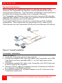
Figure 2. Typical Installation
Transmitter installation
(Refer to Figure 2)
1. Locate the Transmitter unit near the computer.
2. Connect the supplied USB Type A/B cable to the Transmitter unit’s USB
Type B port and to an available USB (1.1 or 2.0) Type A port on the
computer.
3. Connect the supplied DVI cable to the Transmitter unit’s DVI-D port and
to the DVI port on the computer.
4. Connect a CAT5* cable (not supplied) from the Transmitter’s RJ45 port
to a corporate LAN (RJ45) connector.
5. Connect the supplied 5V, 3A power adapter to an AC outlet and to the
Transmitter’s power port.
8
CrystalView Extreme-4 Installation and Operations Manual