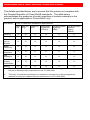
1
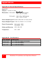
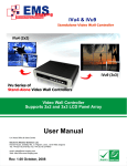
UltraVista LC Video controller/splitter INSTALLATION AND OPERATIONS MANUAL 10707 Stancliff Road Houston, Texas 77099 Phone: (281) 933-7673 WWW.ROSE.COM LIMITED WARRANTY Rose Electronics warrants the UltraVista LC to be in good working order for one year from the date of purchase from Rose Electronics or an authorized dealer. Should this product fail to be in good working order at any time during this one-year warranty period, Rose Electronics will, at its option, repair or replace the Unit as set forth below. Repair parts and replacement units will be either reconditioned or new. All replaced parts become the property of Rose Electronics. This limited warranty does not include service to repair damage to the Unit resulting from accident, disaster, abuse, or unauthorized modification of the Unit, including static discharge and power surges. Limited Warranty service may be obtained by delivering this unit during the one-year warranty period to Rose Electronics or an authorized repair center providing a proof of purchase date. If this Unit is delivered by mail, you agree to insure the Unit or assume the risk of loss or damage in transit, to prepay shipping charges to the warranty service location, and to use the original shipping container or its equivalent. You must call for a return authorization number first. Under no circumstances will a unit be accepted without a return authorization number. Contact an authorized repair center or Rose Electronics for further information. ALL EXPRESS AND IMPLIED WARRANTIES FOR THIS PRODUCT INCLUDING THE WARRANTIES OF MERCHANTABILITY AND FITNESS FOR A PARTICULAR PURPOSE, ARE LIMITED IN DURATION TO A PERIOD OF ONE YEAR FROM THE DATE OF PURCHASE, AND NO WARRANTIES, WHETHER EXPRESS OR IMPLIED, WILL APPLY AFTER THIS PERIOD. SOME STATES DO NOT ALLOW LIMITATIONS ON HOW LONG AN IMPLIED WARRANTY LASTS, SO THE ABOVE LIMITATION MAY NOT APPLY TO YOU. IF THIS PRODUCT IS NOT IN GOOD WORKING ORDER AS WARRANTED ABOVE, YOUR SOLE REMEDY SHALL BE REPLACEMENT OR REPAIR AS PROVIDED ABOVE. IN NO EVENT WILL ROSE ELECTRONICS BE LIABLE TO YOU FOR ANY DAMAGES INCLUDING ANY LOST PROFITS, LOST SAVINGS OR OTHER INCIDENTAL OR CONSEQUENTIAL DAMAGES ARISING OUT OF THE USE OF OR THE INABILITY TO USE SUCH PRODUCT, EVEN IF ROSE ELECTRONICS OR AN AUTHORIZED DEALER HAS BEEN ADVISED OF THE POSSIBILITY OF SUCH DAMAGES, OR FOR ANY CLAIM BY ANY OTHER PARTY. SOME STATES DO NOT ALLOW THE EXCLUSION OR LIMITATION OF INCIDENTAL OR CONSEQUENTIAL DAMAGES FOR CONSUMER PRODUCTS, SO THE ABOVE MAY NOT APPLY TO YOU. THIS WARRANTY GIVES YOU SPECIFIC LEGAL RIGHTS AND YOU MAY ALSO HAVE OTHER RIGHTS WHICH MAY VARY FROM STATE TO STATE. NOTE: This equipment has been tested and found to comply with the limits for a Class B digital device, pursuant to Part 15 of the FCC Rules. These limits are designed to provide reasonable protection against harmful interference when the equipment is operated in a commercial environment. This equipment generates, uses, and can radiate radio frequency energy and, if not installed and used in accordance with the instruction manual, may cause harmful interference to radio communications. Operation of this equipment in a residential area is likely to cause harmful interference in which case the user will be required to correct the interference at his own expense. IBM, AT, and PS/2 are trademarks of International Business Machines Corp. Microsoft and Microsoft Windows are registered trademarks of Microsoft Corp. Any other trademarks mentioned in this manual are acknowledged to be the property of the trademark owner. Copyright Rose Electronics 2010. All rights reserved. No part of this manual may be reproduced, stored in a retrieval system, or transcribed in any form or any means, electronic or mechanical, including photocopying and recording, without the prior written permission of Rose Electronics. Rose Electronics Part # MAN-UV-LC Printed In the United States of America – Revision HAZARDOUS MATERIAL DISCOLSURE The details provided below are to ensure that the product is compliant with the Peoples Republic of China RoHS standards. The table below acknowledges the presence of small quantities of certain materials in the product, and is applicable to China RoHS only. Part Name Toxic or Hazardous Substances and Elements Lead (Pb) Mercury (Hg) Cadmium (Cd) Hexavalent Chromium (CR(VI)) Polybrominated Biphenyls (PBB) Polybrominated Diphenyl Ethers (PBDE) Housing X O O O O X Display X O O O O X Printer Circuit Boards X O O O O X Metal Fasteners X O O O O O Cable Assembly X O O O O X Fan Assembly X O O O O X Power Supply Assemblies X O O O O X Battery O O O O O O O: This toxic or hazardous substance is contained in all of the homogeneous materials for the part is below the limit requirement in SJ/T11363-2006 X: This toxic or hazardous substance is contained in at least one of the homogeneous material for this part is above the limit requirement in SJ/T11363-2006 TABLE of CONTENTS Contents Page # Disclaimer ...................................................................................................... 1 System Introduction ....................................................................................... 1 Features ..................................................................................................... 2 Package Contents ...................................................................................... 2 Compatibility............................................................................................... 3 Rose Electronics web site .......................................................................... 3 Product Registration................................................................................... 3 System Overview ........................................................................................... 3 Front Panel Indicators / Controls ................................................................... 5 Rear Panel Connectors.................................................................................. 6 UltraVista LC Installation ............................................................................... 7 Installing the LCD Displays ........................................................................ 9 Bezel compensation value calculation ..................................................... 10 Mounting the UltraVista LC unit ............................................................... 11 Connecting the cable................................................................................ 11 Using the built-in OSD features................................................................ 12 OSD Menu Structure ................................................................................ 13 Mask Control......................................................................................... 14 Link Control........................................................................................... 14 Slave Mask Setting ............................................................................... 15 Settings ................................................................................................. 16 Warning ................................................................................................ 16 Information............................................................................................ 17 Slave Output Resolution....................................................................... 17 Sync and Power.................................................................................... 17 Firmware Information............................................................................ 18 Serial Number....................................................................................... 18 Remote controller ..................................................................................... 18 Safety ........................................................................................................... 20 Service Information ...................................................................................... 21 Maintenance and Repair .......................................................................... 21 Technical Support .................................................................................... 21 Figures Page # Figure 1. 2 x 2 Installation.............................................................................. 9 Figure 2. 3 x 3 Installation.............................................................................. 9 Figure 3. 1 x 4 Installation.............................................................................. 9 Figure 4. Bezel calculation........................................................................... 10 Figure 5. Serial Connection ......................................................................... 12 Appendices Page # Appendix A- General Specifications ............................................................ 22 Appendix B – Part Numbers ........................................................................ 22 INTRODUCTION Disclaimer While every precaution has been taken in the preparation of this manual, the manufacturer assumes no responsibility for errors or omissions. Neither does the manufacturer assume any liability for damages resulting from the use of the information contained herein. The manufacturer reserves the right to change the specifications, functions, or circuitry of the product without notice. The manufacturer cannot accept liability for damages due to misuse of the product or other circumstances outside the manufacturer’s control. The manufacturer will not be responsible for any loss, damage, or injury arising directly or indirectly from the use of this product. System Introduction The UltraVista LC is the product of choice for those who have the need to produce a high quality, inexpensive video wall. Models are available for a 1x4, 2x2, and 3x3 video wall. The 2x2 and 3x3 models can be expanded to produce a 4x4 or a 9x9 video array. Connect the UltraVista LC directly to a laptop or desktop computer with a single DVI cable and instantly the hi-definition computer image is displayed on a large video wall. No extra set-up is required because the UltraVista LC automatically detects the correct settings. The UltraVista LC can be automatically configured to produce three output modes; video wall mode, clone mode, and replication mode. These modes are automatically configured based on the input resolution received from the video source. The video wall mode accurately splits the input image over the display array. The clone mode displays the same image on all monitors. The replication mode shows the same image on each row of monitors. Video Wall Mode Clone Mode Replication Mode The UltraVista LC requires a high-resolution digital video input signal. This input is split directly over the display array with no image scaling or adjustments needed. Configuring the UltraVista LC can be done from a built-in OSD menu system, a computer connected to the RS-232 serial port or using the remote control unit. UltraVista LC Installation and Operations Manual 1 Features Supports Dual link DVI video input Single-link DVI video outputs Models: 2x2 – 1 dual-link DVI input / 4 single-link DVI outputs 3x3 – 1 dual-link input / 9 single-link DVI outputs 1x4 – 1 dual-link DVI input / 4 single-link DVI outputs (monitors orientated horizontally) Supports video input resolutions up to 3840 x 2400 Output resolutions up to 1920 x 1200 Depending on input resolution, the video output mode is automatically set based on the input resolution (2x2 and 3x3 models - Clone mode, Split mode, Video wall mode) (1x4 model – 3x1 mode or 4x1 mode) Easy adjustments for bezel compensation Expand a 2x2 model easily to a 4x4 display, a 3x3 model to a 6x6 or a 9x9 display array. Configure the 1x4 model with 4 monitors arranged horizontally Adjustments and control can be performed using a remote control or serial commands from a connected computer Compatible with most monitor that supports DVI input. Displays can be LCD, HD Plasma, DLP, Projectors, or others. Package Contents The package contents consist of the following: The UltraVista LC unit Dual-Link DVI cable Power cord Power adapter Remote control Mounting brackets and hardware Installation and operations manual CD Quick Start Guide Cables are usually ordered separately. If the package contents are not correct, contact Rose Electronics or your reseller so the problem can be quickly resolved. 2 UltraVista LC Installation and Operations Manual Compatibility A consumer grade graphic card with high-resolution dual link DVI output is required. The graphic card used must meet or exceed the specifications of the following cards: nVIDA GeForce 9 series – 9800GTX, 9600 GT, 9500GT, 9400GT, etc. nVIDA GeForec 8 series – 8800GT, 8600GT, 8400GT, 8400GS, etc. ATI Radeon HD 3800 Series – 3870, 3850, 3650, 3470, etc. ATI Radeon HD 4600 Series – 4670, 4650, etc. The UltraVista LC is compatible with almost any monitor that supports a DVI input. (LCD, HD Plasma, DLP, or projector) Rose Electronics web site Visit our web site at www.rose.com for additional information on UltraVista LC and other products offered by Rose Electronics that are designed for data center applications, classroom environments, and many other access and switching applications. Product Registration Take advantage of the following when you register your Rose Electronics products online at http://www.rose.com/htm/online-registrationform.htm: Rose Standard Warranty Plus... Free Lifetime Firmware Updates Free Lifetime Technical Support 30 Day Money Back Guarantee Priority “First-in-Line” Status for Tech Support System Overview The UltraVista LC system will take a single high-resolution digital video input and split it correctly over the output display array with no image scaling or adjustments. The UltraVista LC can be controlled from either a computer connected directly to the RS232 port on the unit or using the included remote control. UltraVista LC Installation and Operations Manual 3 MODELS UltraVista LC 1x4 model UltraVista LC 2x2 model UltraVista LC 3x3 model 4 UltraVista LC Installation and Operations Manual Front Panel Indicators / Controls Video Out Indicators LEDs indicate which DVI output port has a video signal. OSD menu controls (See OSD section for Menu and menu selections) Video In Indicator LED indicates a valid input video signal is present Power Indicator LED indicates that power is applied to the unit Menu select button Displays the OSD, Selects items and sets new item values Up arrow button Moves the selection up Down arrow button Moves the selection down Left arrow button Moves the selection left Right arrow button Moves the selection right Enter button Selects the highlighted selection UltraVista LC Installation and Operations Manual 5 Rear Panel Connectors Power On / Off switch DC IN – 12V DC Sync In / Sync Out – Connects from and to additional units Serial DB9F connector – Connects to an external computer’s serial port for external configuration and control. TOP – DVI-D video out connector BOTTOM – DVI-I video out connector NOTE: DVI-I connector supports both digital and analog signals. DVI-D video in connector 6 UltraVista LC Installation and Operations Manual INSTALLATION UltraVista LC Installation Installation of the UltraVista LC is an easy process. The installation consists of installing the LCD displays, mounting the UltraVista LC unit, connecting all of the cables, adjusting the output resolution settings, and adjusting the bezel to align the images. The 2x2 unit’s video output mode is determined by the input resolution of the video source. The 2x2 model can be set-up to display three modes. The 1x1, or clone mode displays the full image on each output monitor. The 2x1, or replication mode displays the input image on across each row of monitors. The 2x2, or video wall mode displays the input image across all monitors. 1x1 2x1 2x2 Clone Mode Replication Mode Video Wall Mode These three modes are determined by the input resolution of the video source as shown in the below table. Mode Input Output Vertical Horizontal Resolution Resolution Hz Hz 1x1 1024x768 1024x768 60 48.36 2x1 2560x1024 1280x1024 60 63.98 3840x1080 1920x1080 50 56.25 3840x1200 1920x1200 50 61.75 2x2 2048x1536 1024x768 60 48.36 63.98 2560x2048 1280x1024 60 2560x1440 1280x720 66 49.37 2560x1600 1280x800 58 48.2 45.32 2720x1536 1360x768 57 60 3840x2880 1920x1440 40 3840x2160 1920x1080 50 56.25 61.75 3840x2400 1920x1200 50 65.28 2560x1920 1280x960 68 36 1280x960 640x480 72 58 55.58 3392x1920 1696x960 1696x960 848x480 54 27.92 * Master to = setting for output to a 3x3 or 2x2 slave input ** Slave to = setting for input from a 2x2 unit Monitor Ratio 4:3 5:4 16:9 16:10 4:3 5:4 16:9 16:10 16:9 Master to 3x3* 16:9 16:10 Master to 2x2* Slave to 2x2** Master to 2x2* Slave to 2x2** UltraVista LC Installation and Operations Manual 7 The 3x3 unit’s video output mode is also determined by the input resolution of the video source. The 3x3 model can be set-up to display three modes, the 2 x 3 mode, the 3 x 2 mode, and the 3 x 3 mode. All three modes display the full image across all monitors. 2x3 3x2 3x3 The three modes are determined by the input resolution of the video source as shown in the below table. Mode Input Output Vertical Horizontal Resolution Resolution Hz Hz 2x3 2048x2304 1024x768 60 48.36 2560x2400 1280x800 58 48.2 2560x3072 1280x1024 60 63.98 2720x2304 1360x768 57 45.32 3x2 3072x1536 1024x768 60 48.36 3840x1600 1280x800 58 48.2 3840x2048 1280x1024 60 63.98 4080x1536 1360x768 57 45.32 48.36 3x3 3072x2304 1024x768 60 66 49.37 3840x2160 1280x720 58 48.2 3840x2400 1280x800 63.98 3840x3072 1280x1024 60 4080x2304 1360x768 57 45.32 1920x1440 640x480 72 36 68 65.28 3840x2880 1280x960 * Master to = setting for output to a 3x3 or 2x2 slave input ** Slave to = setting for input from a 2x2 unit Monitor Ratio 4:3 16:10 5:4 16:9 4:3 16:10 5:4 16:9 4:3 16:9 16:10 5:4 16:9 Slave to 2x2** Master to 2x2* Determine the type of video wall needed based on the UltraVista LC unit and set the video source resolution to one listed. If you have a 3x3 unit and are setting up a 3 x 2 video wall, set the input resolution to one listed for the 3 x 2 mode. See Attachment C for examples of various video wall configurations (2 x 3, 3 x 2, etc). 8 UltraVista LC Installation and Operations Manual Installing the LCD Displays Mount the LCD monitors as shown in figure 1, 2, 3 and 4. All displays should be identical in size and resolution capabilities. When mounting the displays, keep the horizontal and vertical gaps between displays consistent. (See attachment C for optional panel mounting configurations) Figure 1. 2 x 2 Installation Figure 2. 3 x 3 Installation Figure 3. 1 x 4 Installation UltraVista LC Installation and Operations Manual 9 Bezel compensation value calculation When all the displays have been mounted, measure the bezel width and height, and the viewable width and height as shown in figure 4. These values will be entered into the OSD to set the gap compensation which will produce a smooth transition from one display to the next. Bezel Width (mm) Viewable Width (mm) Viewable Height Bezel Height Figure 4. Bezel calculation Calculate the values of “X” and “Y” to enter into the OSD as shown below. (See the OSD section for instructions) “X” value = Bezel Width (mm) --------------------------Viewable Width (mm) “Y” value = Bezel Height (mm) ----------------------------Viewable Height (mm) 10 X X Viewable Width (mm) ---------------------------4 Viewable Height (mm) -----------------------------4 UltraVista LC Installation and Operations Manual Mounting the UltraVista LC unit The UltraView LC unit can be placed on a desk or mounted on a horizontal or vertical surface using the included mounting brackets. To mount the unit using the mounting brackets, remove the four rubber feet and secure the mounting brackets to the unit using the same holes and screws as shown below. The installation location must be: Centrally located so all cables can connect to the unit* Out of direct sunlight No items placed on top of the unit On a firm surface or secured with the mounting brackets Away from any moisture or liquids Observe proper cable strain relief techniques * If extended distances are needed from the UltraVista LC to the video source or to the display monitors, Rose Electronics’ video extender line can extend this distance up to 400 feet using CATx cabling or 6 miles over fiber cabling. Connecting the cable Attach the provided DVI video cable from the UltraVista LC DVI input connector to the DVI video source. If the video source is VGA, a VGA to DVI converter must be used. Each monitor connects directly to the corresponding DVI connector on the UltraVista LC’s rear panel. Refer to Figure 1, 2, and 3 for monitor numbering. Connect a DB-9MF serial cable to the DB9F serial connector on the UltraVista LC rear panel and to the DB-9M serial connector on a computer that will be used to send serial commands to the unit. See Figure 5 for an example of the cable installation and the RS232 section for instructions on sending serial commands to the unit. UltraVista LC Installation and Operations Manual 11 Serial cable Figure 5. Serial Connection All models install and configure in the same manor. Connect the DVI video source to the unit Connect each display monitor to the unit Connect a serial cable from the unit to a controlling computer Using the built-in OSD features To invoke the built-in OSD, press the MENU button on the front panel. The OSD will display on the monitor connected to the DVI output port #1. (Note: All cable connections and power must be applied) 12 UltraVista LC Installation and Operations Manual OSD Menu Structure To reset the UltraVista LC to factory defaults, Press the “UP”, “Down”, and “Enter” buttons simultaneously until the “Reset to Mfg Default” message appears on the monitor connected to DVI output connector #1. Table 1 below shows the OSD menu structure. Menu Options Description Mask Control MASK Toggles the mask function ON / OFF X Sets the horizontal mask value* Y Sets the vertical mask value* Link Control LINK Toggles the link between the master (2x2 and 3x3 only) video unit’s mask value and the slave’s value Scan Toggles the scan function ON / OFF for detecting the attached slave units Slave Mask Setting DVI Displays DVI output settings with (2x2 and 3x3 only) link on Displays individual settings with link off X Sets the horizontal mask value Y Sets the vertical mask value Settings OUT Sets the output resolution MODE Sets the output mode Warning Change Warning that the output resolution Setting Information OUT Displays the Units output resolution IN Displays the Units input resolution Slave Output Resolution DS (2x2 and 3x3 only) H Slave’s horizontal output resolution V Slave’s vertical output resolution Sync and Power SYNC Power Turns the power on and off Version Information FPGA FPGA chip version number CPLD CPLD chip version number FW Firmware version number Model Information Name Displays the model name SN Displays the model serial number * See page 8 for “X” and “Y” value calculations Table 1. OSD Menu Structure UltraVista LC Installation and Operations Manual 13 To navigate within the OSD system, first press the menu button on the front panel. The Mask Control window will display. Use the up or down arrow buttons to select (Highlight) an item (MASK, X, OR Y). Once selected, use the left or right arrow buttons to change the item value. When the correct values are set, press the Enter button to save the new values. With no item within the Mask Control window or any other displayed menu selected (No item Highlighted) pressing the left or right arrow buttons will advance to the next or previous menu window. Example: Pressing the Menu button displays the Mask Control window. With no item selected, pressing the right arrow button will display the Link Control window, press the right arrow button again and the Slave Mask Setting window will display. Following are examples and descriptions of each menu item. Mask Control The mask control menu compensates for the gaps between the monitors. Selection Description MASK Toggles the Mask function ON or OFF X Adjusts left to right gap compensation (See Figure 4 for calculating X) Y Adjusts top to bottom gap compensation (See Figure 4 for calculating Y) Link Control Link control enables (ON) or disables (OFF) the master unit to automatically adjust the mask settings of the attached slave units. Scan setting detects the attached slave units 14 UltraVista LC Installation and Operations Manual Slave Mask Setting Mask Link = ON All slave units have the same settings Mask Link = OFF DVI 1 = settings for unit #1 DVI 2 = settings for unit #2 DVI 3 = settings for unit #3 DVI 4 = settings for unit #4 /X displays the horizontal bezel setting /Y displays the vertical bezel setting UltraVista LC Installation and Operations Manual 15 Settings OUT = Output resolution from the UltraVista LC MODE = Mode setting of the UltraVista LC VW = 2x2 mode on the UltraVista LC 2x2 unit S = 2x1 mode on the UltraVista LC 2x2 unit C = 1x1 mode on the UltraVista LC 2x2 unit 3x3 = 3x3 mode on the UltraVista LC 3x3 unit 2x3 = 2x3 mode on the UltraVista LC 3x3 unit 3x2 = 3x2 mode on the UltraVista LC 3x3 unit Warning The warning message indicates that the output resolution on the computer should be adjusted to the resolution value shown. 16 UltraVista LC Installation and Operations Manual Information The information menu shows the current input and output resolutions. Slave Output Resolution Shows the current slave output resolution / DS x = slave setting for designated unit (1) H = horizontal resolution for the designated unit V = vertical resolution for the designated unit Sync and Power SYNC = for debugging Power = Turns unit power OFF UltraVista LC Installation and Operations Manual 17 Firmware Information FPGA = Current version of the FPGA chip CPLD = Current version of the CPLD chip FW = Current UltraVista LC firmware version Serial Number Displays the model name and serial number Remote controller All UltraVista LC models are supplied with a remote control. The remote control provides the same functions as the front panel push-buttons. 18 Power: Menu: Left: Right: Up: Down: Enter: Turns the UltraVista LC unit on or off Displays the OSD menu on monitor #1, selects items, and sets new values Moves the selection left Moves the selection right Moves the selection up Moves the selection down Exits from any menu UltraVista LC Installation and Operations Manual Troubleshooting No Image on One Monitor Check that the monitor is turned on Check that the power source for the monitor is turned on Check that the power source has the correct power rating Make sure the LCD panel power cables are securely fastened to the monitor and to the power source Check the monitor is connection UltraVista LC Installation and Operations Manual 19 Safety Safety The UltraVista LC has been tested for conformance to safety regulations and requirements, and has been certified for international use. Like all electronic equipment, the UltraVista LC should be used with care. To protect yourself from possible injury and to minimize the risk of damage to the Unit, read and follow these safety instructions. Follow all instructions and warnings marked on this Unit. Except where explained in this manual, do not attempt to service this Unit yourself. Do not use this Unit near water. Assure that the placement of this Unit is on a stable surface. Provide proper ventilation and air circulation. Keep connection cables clear of obstructions that might cause damage to them. Use only power cords, power adapter and connection cables designed for this Unit. Keep objects that might damage this Unit and liquids that may spill, clear from this Unit. Liquids and foreign objects might come in contact with voltage points that could create a risk of fire or electrical shock. Do not use liquid or aerosol cleaners to clean this Unit. Always unplug this Unit from its electrical outlet before cleaning. Unplug this Unit refer servicing to a qualified service center if any of the following conditions occur: The connection cables are damaged or frayed. The Unit has been exposed to any liquids. The Unit does not operate normally when all operating instructions have been followed. The Unit has been dropped or the case has been damaged. The Unit exhibits a distinct change in performance, indicating a need for service. 20 UltraVista LC Installation and Operations Manual Service Service Information Maintenance and Repair This Unit does not contain any internal user-serviceable parts. In the event a Unit needs repair or maintenance, you must first obtain a Return Authorization (RA) number from Rose Electronics or an authorized repair center. This Return Authorization number must appear on the outside of the shipping container. See Limited Warranty for more information. When returning a Unit, it should be double-packed in the original container or equivalent, insured and shipped to: Rose Electronics Attn: RA__________ 10707 Stancliff Road Houston, Texas 77099 USA Technical Support If you are experiencing problems, or need assistance in setting up, configuring or operating your QuadraVista, consult the appropriate sections of this manual. If, however, you require additional information or assistance, please contact the Rose Electronics Technical Support Department at: Phone: (281) 933-7673 E-Mail: [email protected] Web: www.rose.com Technical Support hours are from: 8:00 am to 6:00 pm CST (USA), Monday through Friday. Please report any malfunctions in the operation of this Unit or any discrepancies in this manual to the Rose Electronics Technical Support Department. UltraVista LC Installation and Operations Manual 21 Appendices Appendix A- General Specifications Inputs DVI Outputs – 4 x DVI / 9 x DVI W D H Dimensions 2x2 model – 9.0 x 7.1 x 1.85 (Inches) 230 x 180 x 47 (mm) 3x3 model – 11.6 x 7.4 x 1.85 (Inches) 295 x 188 x 47 (mm) Power Adapter Input 90 VAC to 264 VAC / 47 Hz to 63 Hz Power Adapter Output 11.52 V to 12.48 V / 2.1 A / 25 W Power Consumption 2x2 model - 10 W 3x3 model - 17 W Safety and Emission CCC, CE, FCC Temperature 0ºC – 40ºC Appendix B – Part Numbers Part Number Description VWL-B114D 1 x 4 Video wall display (Horizontal) VWL-B122D 2 x 2 Video wall display VWL-133D 3 x 3 Video wall display 22 UltraVista LC Installation and Operations Manual UltraVista LC Installation and Operations Manual 23 10707 Stancliff Road Phone: (281) 933-7673 Houston, Texas 77099 Internet: WWW.ROSE.COM