1
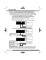
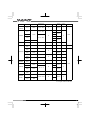
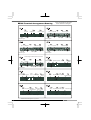
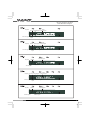
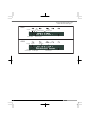
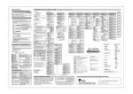
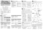
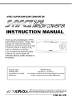
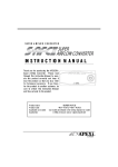
VTEC AIR FLOW CONVERTERⅡ
WIRING DIAGRAM BY MODEL
This document describes car models to which the VTEC Airflow
Converter II (Product code: 401-A915/401-A815) is applicable,
and ECU terminal arrangement drawings. For the operating
method and precautions for the VTEC Airflow Converter II, refer
to the Instruction Manual.
For installing the VTEC Airflow Converter II, both this document
and the Instruction Manual are required.
Even if the car model and manufacturing year coincide with the
contents described in this document, this product may not be
installed in a special specification vehicle or remodeled vehicle.
The manufacturing years of applicable vehicles are as of March
2005. For application to vehicles released after that, consult
the respective APEXERA business office for information.
1
■Contents
■Introduction _____________________________________________________ P2
■Precaution on Installation ______________________________________ P3
■Installation ______________________________________________________ P5
■ECU Arrangement Drawing _____________________________________ P10
■How to Refer to the ECU Terminal Arrangement Drawing ____ P11
Table of Applicable Models.......................................................... P12
ECU Terminal Arrangement Drawing ......................................... P15
■Introduction
“Safety precautions” are described in the Instruction Manual. Please read them before
starting the installation work.
“Signal words and their meanings” are described in the Instruction Manual for this product.
The “Engine Control Unit” is abbreviated as “ECU” in this document.
! CAUTION
●Regarding the installation of this product, be sure that it is
installed by an experienced professional.
After completion of the installation, hand over this document, Instruction Manual, and
Warranty to the customer (user).
●Do not pull the harness of the vehicle and the harness of this
product,
Wire breaking or a short circuit may occur, thereby giving damage to this product and
the vehicle.
●When removing or connecting a connector, be sure to unlock
the locked (claw) status beforehand.
When the connector is provided with a fixing bolt, loosen this
bolt completely before pulling out the connector.
The connector may be damaged.
●Arrange the harness of this product and the harness of the
vehicle in portions that are not at a high temperature or are not
movable. Arrange them so that water may not be splashed over
them.
Wire breaking or a short circuit may occur, thereby giving damage to this product and
the vehicle.
●Do not arrange the harness of this product and the harness of
the vehicle near a sharp-edged material. Do not put the harness
between materials by applying pressure to it.
Wire breaking or a short circuit may occur, thereby giving damage to this product and
the vehicle.
2
■Precaution on Installation
●When installing this product, do not use any electro-tap in any
case.
Using the electro-tap makes the contact status unstable. Its contact defect may causes
a malfunction to the product and damage to this product and the vehicle.
Be sure to use the attached splice and dedicated tools such as cutting pliers for electric
work to install the product securely.
●Insulate the metallic portion of the harness securely with a
vinyl tape.
●Caulking the plug
(1) Peel off the coating of
the wires about 8 mm
(2) Cover with a sleeve
(4) Caulk securely
(3) Fold the wires
※Check if caulking has been performed securely by referring to the following figure
Caulk the conductors by these portions
Make the caulking thrust into the wire
Caulk the coating by these portions
●Caulking the splice
(1) Peel off the coating of the wires to be
connected about 5 mm
(2) Peel off the wires to be
branched about 10 mm
(3) Entwine the wires
(4) Caulk securely
※Insulate the caulked portion securely with a vinyl tape
3
●The ground conductor of this product has two branches (black and brown).
This has a very important significance to secure the voltage conversion
accuracy. Connect the ground conductor by referring to the following figure.
Installing the ground conductor in a different way from the connecting method
specified by A’PEX will give damage to this product and the mounted car engine.
Correct Connecting Method for the Ground Conductor
Connect the ground conductor to two positions of the same line.
Be sure to connect the brown wire to the ECU side.
Allow a space of 1 cm or more between the connecting point of the black wire
and the connecting point of the brown wire.
Vehicle harness
Engine
Control Unit(ECU)
Brown wire (ground)
Black wire (ground)
Wrong Connecting Method for the Ground Conductor
Vehicle harness
Engine
Control Unit(ECU)
Unite the ground
wires into a single
line.
Brown wire (ground)
Black wire (ground)
Vehicle harness
Engine
Control Unit(ECU)
Do not connect the
ground conductor
to any position
(e.g. chassis ground)
other than the
specified position.
Brown wire (ground)
Black wire (ground)
The above figure explains only the connection of the ground conductor. For the
other signal lines, refer to page 6 and page 7. Be sure to wire the power cable,
ground conductor and other signal lines to the positions specified by A’PEX.
4
■Installation
●Connecting the VAFC II
1.Remove the negative (-) terminal of the battery.
advice!
There is some setting data on car audio, car navigation, etc. that is backed up by battery power
supply. We recommend you to take a note of the data beforehand lest they should be lost.
! CAUTION
●Before starting the wiring work, remove the negative
terminal of the battery.
If not, a fire will be caused by short circuit, thereby giving damage to electric parts.
If the ECU connector is removed while the battery is connected, the engine
warning lamp may light up continuously regardless of whether the VAFC II is
installed or not. At this time, you must ask the distributor of each car model to
perform maintenance and inspection.
●We shall not take all responsibility for damage of the
vehicle or related devices that may be caused by
installation error.
2.Locate the Engine Control Unit (hereafter referred to as ECU) of the vehicle by referring
to the Wiring Diagram by Model.
3.Connect the harness attached to the V-AFC II securely to the power cable of the vehicle
harness, grounding conductor, engine revolution signal wire, throttle signal wire, and
TDC signal wire, VTC signal wire, and VTM signal wire that are connected to the ECU,
by referring to the Wiring Diagram by Model. (Refer to page 7.)
Connect the red wire to the IG power.
Connect the green wire to the engine revolution signal wire.
Connect the gray wire to the throttle signal wire.
Connect the black wire to the grounding conductor.
Connect the brown wire to the grounding conductor.
Connect the orange wire to the VTC cam signal wire ※
Connect the light blue wire to the TDC signal wire. ※
Connect the blue wire to the VTM signal wire. ※
※The RDC signal wire and the TCC cam signal wire are limited to vehicles with an
i-VTEC.
※The VTM signal wire is limited to vehicles with a V type engine and some car models.
※For the details of the above TDC signal, VTC cam signal, and VTM
signal, refer to the terminal arrangement drawings on and after page
5
■Installation (cont.)
! CAUTION
●Be sure to connect the black wire and the brown wire of the
harness attached to the VAFC II to the ground conductor.
This product may not function normally, thereby giving damage to the product and the
engine.
●When locating each wire, take special care not to cause a
short circuit.
A fire may be caused or electric devices may be damaged.
●Install the splice for branching securely without any contact
defect.
A fire may be caused or electric devices may be damaged.
4.Cut the pressure signal wire or VTEC solenoid signal wire of the vehicle harness
connected to the ECU and install a plug by referring to the Wiring Diagram by Model.
For some applicable models, cut the VTM signal wire and install a plug.
Pressure sensor signal
Plug receptacle: Pressure sensor side
Plug: ECU side
VTEC solenoid signal
VTM signal
Plug receptacle: ECU side
Plug: VTEC solenoid side
Plug receptacle: ECU side
5.Connect the harness attached to the V-AFC II to the plug installed in 4.
Pressure sensor signal
Plug receptacle: White wire
Plug: Yellow wire
Plug receptacle: Purple wire
VTEC solenoid signal
VTM signal
Plug: Pink wire
Plug receptacle: Blue wire
6.Make sure to insulate the unused wires and plugs with a vinyl tape.
※Poor insulation may result in short-circuit, which leads to a danger.
7.Connect the negative (-) terminal of the battery.
6
■Installation (cont.)
●Wire connecting method
Red wire (IG power)
Red wire (IG power)
Black wire (ground)
Brown wire (ground)
Green wire (rpm)
Gray wire (throttle signal)
Orange wire (VTC cam signal)
Light blue wire (TDC signal)
Engine
Control Unit(ECU)
Blue wire (VTM signal)
Purple wire (VTEC solenoid signal input)
Pink wire (VTEC solenoid signal output)
Yellow wire (pressure signal output)
White wire (pressure signal input)
Plug
Plug receptacle
Splice
! CAUTION
●Be sure to connect the brown wire to the ECU side from the
black wire.
This product may not function normally, thereby giving damage to the product and the
engine.
●Be sure to connect the two wires of the IG power supply.
7
! WARNING
●Install the V-AFC II so that it may not interfere with driving.
Normal driving operations may be prevented, resulting in an accident.
●Do not install the V-AFC II in a high-temperature place or a
place exposed to direct water.
An electric shock or fire may be caused or electric parts may be damaged. A
malfunction may be caused, thereby giving damage to the vehicle.
●When passing the connecting harness of the V-AFC II, arrange
the harness so as not to touch the moving portion.
The connecting harness may be cut or short-circuited. The V-AFC II will be damaged,
thereby giving damage to the vehicle and electric parts.
●Checking after installation
After installing the V-AFC II, check the following items once again.
・Check if the harness attached to the V-AFC II is securely connected.
・Check if the harness is not unnaturally arranged.
・Check if the V-AFC II is securely fixed.
・Check if the negative (-) terminal of the battery is securely connected.
●Turn on the ignition switch. (Do not start the engine in any
case.)
Check the following contents after turning on the ignition switch.
・Check if characters are correctly displayed on the display part of the V-AFC II.
If the display of this product is not made correctly, stop using the product
immediately and make contact with the distributor or your nearest A’PEX
business office.
・Check if any abnormal noise or offensive small is produced from the V-AFC II
and the vehicle.
If any abnormal noise or offensive smell is sensed, stop using this product
immediately and make contact with the distributor or your nearest A’PEX
business office.
●Initial setup
・If no abnormality is found with the ignition switch ON, perform initial setup for the
V-AFC II.
・ Perform sensor number setting, number-of-cylinders setting, VTEC type setting, throttle
sensor voltage checking, throttle sensor type setting, and throttle opening learning according
to “Initial Setup” on page 13 in the separate Instruction Manual. And set the reference cam
angle for vehicles with an i-VTEC.
When the engine is ready to start after initial setup, the installation work is
completed.
8
! CAUTION
●Do not start the engine in any case before the initial setup is
performed.
If the engine is started without initial setup, the engine may be damaged. Set the
corresponding items by referring to page 13 in the Chapter pertaining to “Initial Setup”
in the separate Instruction Manual with regard to the initial setup method.
! WARNING
●When the engine warning lamp in the meter comes on, you
must ask the distributor of the model for inspection. If the
vehicle is driven at a high speed with the engine warning lamp
ON, the engine may be damaged, leading to an unexpected
accident. Do not drive the vehicle in this status in any case.
9
■ECU Arrangement Drawing
●Perform operations by referring to the symbols in the
corresponding columns of the tables of applicable models
on and after page 12.
L
P
D
C
B
F
E
A
N
M
G
O
I
H
K
10
J
A : Lower part of the passenger seat dash side
B : Right side of the glove box
C : Foot position of the passenger seat
D : Inner part of the glove box
E : Inner part of the center console
F : Under the driver’s seat
G : Under the passenger seat
H : Near the steering column
I : Left side of the meter panel
J : Lower part of the driver’s seat dash side
K : Left side of the center console
L : Engine room
M : Before the rear trunk
N : Behind after the driver’s seat
O : Behind the passenger seat
P : Upper inner part of the center console
■How to Refer to the ECU Terminal
Arrangement Drawing
This ECU terminal arrangement drawing is on the
assumption that the connector is viewed from the
direction of the arrow.
The direction of the ECU varies depending on each
vehicle. Perform the installation work after confirming
the connector shape and the number of pins carefully.
! WARNING
●If any abnormal noise or offensive smell is sensed during the
installation work of this product, stop the work immediately
and make contact with the distributor or your nearest A’PEX
business office.
Continuing the work in such a condition may cause an electric shock or fire or give
damage to electric devices.
11
■Table of Applicable Models
Car name
Car model
Engine model
Manufacturing
year
S2000
AP1
F20C
‘99.4∼‘03.9
※Excluding VTEC 3 cars
ECU
position
A
Remarks
Type R※1
(220ps)
DC5
INTEGRA
(including the
’98
specification)
K20A
‘01.7∼‘03.8
D
‘95.9∼‘01.6
DC2
DB8
B18C
DA8
DA6
B16A
‘89.4∼‘93.5
EP3
K20A
‘01.12∼※
H6-a
1
1
H7-a
iS ※1
3
160ps ※2
H7-b
M/T
H4-a
A/T
H2-c
M/T
H3-a
A/T
H2-b
C
D17A
EU2
EU1
D15B
‘00.10∼‘03.8
3
1
H1-a
Type R※1
(220ps)
H7-a
1
Si ※2
H7-b
3
Excluding
lean-burn
cars
H8-a
3
B16B
‘00.8∼‘00.9
H6-a
‘98.9∼‘00.7
H5-a
‘97.6∼‘98.8
H4-a
PR-6
1
‘98.9∼‘00.7
H5-a
A
EK4
B16A
‘95.9∼‘98.8
H4-a
EG6
‘91.9∼‘95.8
CIVIC
FERIO
EG4
D15B
EF9
B16A
ES4
ES3
D17A
ES2
ES1
D15B
Excluding
carburetor
cars
‘89.9∼‘91.8
C
‘00.10∼‘03.8
D
Excluding
lean-burn
cars
H3-a
2
H1-a
1
H8-a
3
‘98.9∼‘00.7
H5-a
‘95.9∼‘98.8
H4-a
EK4
1
B16A
A
EG9
1
‘91.9∼‘95.8
CIVIC
COUPE
12
Sensor
type
D
EU4
EU3
EK9
VTEC
No.
A
‘93.5∼‘95.8
CIVIC
Terminal
drawing
EG8
D15B
EJ1
D16A
H3-a
2
‘92.10∼‘95.8
A
H3-a
※1 Japanese model only.
※2 USA model only.
1
Car name
CR-X
Car model
Engine
model
EG2
B16A
EG1
EF8
Manufacturing
year
ECU
position
‘92.3∼‘95.10
A
Remarks
Terminal
drawing
Sensor
type
1
H3-a
D15B
B16A
VTEC
No.
2
‘89.9∼‘92.2
C
H1-a
1
BB8
‘96.12∼‘00.9
H4-a
BB6
PRELUDE
H22A
BB4
BB1
ACCORD
EURO R
C
‘91.9∼‘96.11
CL1
H22A
‘00.6∼‘02.9
CL9
K24A
‘02.12∼※
H3-a
With
TRC
H2-a
E
M/T
‘00.6∼‘02.9
CL3
Without
TRC
1
H6-a
1
H9-c
1
H6-a
A/T
H5-a
CF5
ACCORD
F20B
E
M/T
H6-a
‘97.9∼‘02.9
CF4
3
A/T
H5-a
CF3
F18B
CD6
H22A
CD5
F22B
PR-6
‘93.9∼‘97.8
C
CM2
K24A
H3-a
Type
24T
‘02.11∼※
CM3
H9-c
1
‘00.6∼‘02.10
CL2
H23A
ACCORD
WAGON
‘99.1∼‘02.10
CH9
CF7
CF6
F23A
‘97.10∼‘02.10
CF2
H22A
‘96.9∼‘97.9
E
H5-a
3
H3-a
FIT
MOBILIO
SPIKE
CE1
F22B
‘94.3∼‘97.9
C
GD4
GD3
L15A
‘02.9∼‘03.9
B
GK2
GK1
L15A
‘02.9∼※
B
J30A
TA3
TA2
TA1
3
H8-a
3
H5-b
2
H5-a
3
‘00.2∼‘03.12
TA4
AVANCIER
H8-a
Load
Sensing
E
‘99.9∼‘03.12
F23A
13
Car name
Car model
Engine model
Manufacturing
year
ECU position
TORNEO
EURO R
CL1
H22A
‘00.6∼‘02.9
E
M/T
‘00.6∼‘02.9
CL3
Remarks
Terminal
drawing
Vehicle
No.
H6-a
1
Sensor type
H6-a
A/T
H5-a
CF5
F20B
E
TORNEO
‘97.9∼‘02.9
CF4
3
M/T
PR-6
H6-a
A/T
H5-a
LAGREAT
CF3
F18B
RL1
J35A
‘99.6∼‘04.4
E
RB2
RB1
K24A
‘03.10∼※
B
RA9
RA8
J30A
‘00.1∼‘03.9
160ps
H5-b
2
H9-d
3
H5-b
2
H5-a
3
H4-b
2
H5-a
3
H9-a
3
PR-11 ※1
E
ODYSSEY
STEP
WAGON
RA7
RA6
F23A
‘99.12∼‘03.9
RA5
J30A
‘97.10∼‘99.11
C
RA4
RA3
F23A
‘97.8∼‘99.11
RF4
RF3
K20A
‘01.4∼‘03.5
E
‘01.1∼※
RN4
PR-6
K20A
H9-a
RN3
STREAM
CR-V
D
3
‘00.10∼※
RN2
RN1
D17A
RD5
RD4
K20A
UA5
J32A
UA4
J25A
INSPIRE
SAVER
H9-b
‘01.9∼‘04.8
D
H9-a
3
‘98.10∼‘03.5
E
H5-b
2
※1 Program Version 2.05a after.
14
■ECU Terminal Arrangement Drawing
IG power
VTEC
solenoid signal
IG power
Ground
VTEC
solenoid signal
rpm
Throttle signal
rpm
Ground
VTEC
solenoid signal
rpm
Pressure signal
VTM signal
Pressure signal
Throttle signal
VTM signal
※It is not necessary to wire for the
vehicle without the VTM signal
IG power
Ground
IG power
rpm
VTEC
solenoid signal
Pressure signal
VTM signal
Throttle signal
Pressure signal
Throttle signal
Ground
※There might not be free space of connector
rpm
Ground
VTEC
solenoid signal
VTEC
solenoid signal
Pressure signal
IG power
Ground
rpm
IG power
Ground 2
Throttle signal
VTEC
solenoid signal
Ground 1
Pressure
signal
rpm
Pressure
signal
rpm
rpm
IG power
Ground IG power Throttle
Throttle signal
VTM signal
VTM
signal
VTEC
solenoid signal
Pressure VTM
signal signal
Throttle signal
※Please select either ground 1 or ground 2.
VTEC
IG power solenoid signal
Ground
rpm
Throttle signal
VTEC
IG power solenoid signal
Ground
Pressure signal
Pressure signal
Throttle signal
15
※It is not necessary to wire for the
vehicle without the VTM signal
IG power
VTC cam signal
IG power
VTEC
Ground Throttle signal solenoid signal
Pressure signal
TDC
signal
VTEC
Ground Throttle signal solenoid signal
VTC cam signal
TDC
signal
IG power
Ground
Pressure signal
Pressure signal
IG power Ground
Throttle signal
VTC cam signal
Throttle signal
16
TDC
signal
Ground
VTM
rpm
VTEC
solenoid signal
Throttle signal
IG power
rpm
rpm
VTEC
solenoid signal
Pressure signal
rpm
VTEC
solenoid signal
Pressure signal
rpm
※It is not necessary to wire for the
vehicle without the VTM signal
H9-c
IG power
Ground
Throttle signal
TDC
signal
VTC cam signal
VTEC
solenoid signal
rpm
Pressure signal
H9-d
IG power
VTEC
solenoid signal
Ground
Throttle signal
TDC signal
VTC cam signal
Pressure signal
rpm
17
Notes
1. The contents of this document are subject to change without previous notice.
2. The contents of this document have been prepared with extreme care. However,
if you find a doubt, error, or other fault, inform us of it.
3. A part or all of this document may not be reproduced in any form without prior
written permission, and also may not used without the prior written permission of
APEXERA CO., LTD. under the copyright except for private use.
・The company names and product names described in this document are the
registered trademarks or brands of the respective companies.
・contact are as of Apr.1, 2005. Note that this information is subject to change.
■Revision Record
No,
Date of issue
Part No. of Wiring
Diagram by Model
Edition
1
May. 20, 2003
7107-0300-00
First edition
2
Aug.1, 2003
7107-0300-01
Second edition
3
Dec.26, 2003
7107-0300-02
Third edition
4
Jun.10, 2004
7107-0300-03
Fourth edition
5
Apr.1, 2005
7107-0300-04
Fifth edition
APEXERA Co.,Ltd.
Change of description
http://www.apexera.co.jp
Head office : 1-17-14 Tanashioda,Sagamihara-city Kanagawa,229-1125 JAPAN
ph+81-42-778-3991 fx+81-42-778-4495
USA office
http://www.apexi-usa.com
A’pex Integration,Inc.: 330W.Taft Orange,CA.92865,USA
ph : (714)685-5700 fx : (714)685-5701
18