Transcript
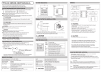
和文の説明は裏面にあります。
OPERATION FLOW AND SETTING MENU
TTM-000 SERIES USER'S MANUAL
1
/16 DIN. DIGITAL TEMPERATURE CONTROLLER
●Power ON
CAUTION
: Press key
Set the temperature
required
MODE key
MODE key more
than 2 seconds
MODE key, return to A
●FUNC key
FUNK key operates on the selected
setting mode 7.
Refer to Ex.2.
Ex.1.
MODE key
2. Input type setting
Select input type
Refer to Table 1.
B. Priority displays. Refer to Ex.1.
SET0 : Priority displays by
setting and shows max.9
displays by setting.
a correct model (See the following "Model Configuration" ).
●The following symbol marks
provide to prevent incident or damage. Kindly
refer to the details of the WARNING/CAUTION when using for the first time.
●Another copy of the user's manual "Advanced Version" is provided at
customer's request.
Owing to mishandling, it may
cause some damage to
the unit or the operator
getting slight injury.
Primary displays
Process value
Setting value
●When having the purchased controller at hand, please be sure that its unit is
WARNING
Initial setting mode
Calling display
●Operate mode display
A.
NOTICE/WARNING BEFORE OPERATION USE
Due to mishandling,
serious dangers may occur to
the operator such as death,
electrocution and a skin burn.
<SET1:Initial Setting>
1. Initial setting display
Shows for 4 seconds
(Warming up)
Thank you for purchasing model TTM-000 SERIES
Digital Temperature Controller.
Please go through this Instruction Manual carefully
and use the unit in proper manner.
Priority displays & its setting
This function is to shift the most essential
screens on setting mode into operation mode
as a priority. Please select priority displays
through priority display setting.
eg. : Basic display
Output 1 manipulated value
Setting high limit for event Output 1
CAUTION
WARNING
●Make sure the correct wiring connection before turning on electricity.
Mis-wiring may cause malfunction of the unit and fire.
●Never modify the unit to prevent damage or incident such as
malfunction and fire etc.
・Please put this user's manual aside for your reference, when
operating the unit.
・Copy or reprint of this manual, wholly or partially, is not allowed.
・The contents of this manual may change without notice in future.
ACCESSORY & CONFIGURATION
1) Please be sure that the unit enclosed in packing carton is a right model
before using.
2) Kindly check the following accessory being contained in that carton box.
● Installation Attachment (For installation, please see "INSTALLATION
AND WIRING" on the back.)
● This user's manual : 1 copy
3) Model Configuration
Model
Input
Output 1
Option
T T M - □ □ □ −□ −□ −A □ □ □
MODEL Front Dimensions
002 24×48 mm
004 48×48 mm
X04 48×48 mm
005 96×48 mm
006 48×96 mm
007 72×72 mm
009 96×96 mm
CODE Input Type
NIL Thermocouple (K, J, R,
T, N, S, B)
R.T.D. (Pt100, JPt100)
2 0–5V, 1–5V, 4–20mA
CODE Output 1
R Relay contact
P SSR drive voltage
I Current 4–20 mA DC
Option
CODE
B Output 2 Relay contact
B or P selectable
P Output 2 SSR drive voltage
R EV 2 Relay contact Not optional for TTM-002/004.
When DI is selected for
TTM-005, 006, 007 or 009,
this option is not available.
D CT input When DI is selected for TTM-002/004,
this option is not usable.
When I output (4–20mA) is selected,
this option is not provided.
E DI (Digital input) When CT is selected for TTM-002/004,
this option cannot be obtained.
When EV 2 is selected for TTM-005, 006,
007 or 009, this option cannot be chosen.
M Communication RS-485
* A (EV1) provided in the standard specifications.
* Without output 2, EV2 is not available.
* Output 2 is equally used as EV2, but both not
activated simultaneously.
Control Output
Control Method
Operation Environment
Storage Environment
Weight
Location of the Unit Setting
CAUTION
Installation condition
Ex.3. To select PID
Feature of type A and B
Type A Ordinary PID
Type B Over shoot protection PID
If control is unstable under self-tuning,
please change to type A or B and also to ON/OFF control.
Ex.4.
●
●
ARW
Anti-reset wind-up take effect for overshooting
by over-integral of PID control action.
ARW controls integral action(PV accords with SV).
If integral value goes down, it takes effects.
If integral value is set "0", it stops integral action.
Table1. To select input sensors and setting range.
unit:℃
0.0 Setting
Symbol
Low limit∼High limit
00 K Thermocouple − 200∼1372 −199.9∼990.0
01 J
〃
− 200∼ 850 −199.9∼850.0
02 R
〃
−
0∼1700
03 T
〃
− 200∼ 400 −199.9∼390.0
04 N
〃
− 200∼1300 −199.9∼990.0
05 S
〃
−
0∼1700
06 B
〃
−
0∼1800
10 Pt100
− 199∼ 500 −199.9∼500.0
11 JPt100
− 199∼ 500 −199.9∼500.0
20 DC0 – 5V
−1999∼9999 −199.9∼999.9
−19.99∼99.99
−1.999∼9.999
21 DC1 – 5V
−1999∼9999 −199.9∼999.9
−19.99∼99.99
−1.999∼9.999
22 DC4 – 20mA −1999∼9999 −199.9∼999.9
−19.99∼99.99
−1.999∼9.999
<SET3:Event Output 1>
37. Event output 1 setting
EV1 setting mode
Calling display
▼ KEY
MODE key
10. High limit setting in SV limiter
MODE key
38. Function setting for EV 1
Display of high limit setting * Current/Voltage
of setting value.
「9000」
(Within setting range of Table 1)
Select below functions.
MODE key
11. Low limit setting in SV limiter
Display of low limit setting * Current/Voltage
of setting value.
「−1000」
(Within setting range of Table 1)
MODE key
4. Zero point setting for PV correction
MODE key
12. Control mode setting
When measurement value
comes an error, set the
correction value (Addition)
Usable for control mode
setting
MODE key
5. Filtre input
Control performance
Non-control performance
(Manipulated value low limiter output)
CR filter effect is operational on
software when making first-order
lag operation to process value (PV).
Manual control
MODE key
13. Selection of control type setting
MODE key
6. Position of decimal point
Not required
Required
Current/Voltage
PID,
Refer to Ex.3.
Not required
1 digit
2 digits
3 digits
0:Type A
1:Type B
Control
output 1
1:PID
2:ON/OFF
Control output 2
0:None
1:PID
2:ON/OFF
3:Event output
MODE key
14. Change of normal or reverse
MODE key
7. FUNK key setting (Refer to Ex.2.)
Key lock setting for protection
of error operation.
Selectable below functions
None
All lock
Operation mode lock only
Except operation mode
Set high limit value.
Set high limit value.
MODE key
40. Low limit setting for EV 1
MODE key
50. Low limit setting for EV 2
Set low limit value.
Set low limit value.
MODE key, return to 1
MODE key
17. AT coefficient setting
Coefficient is multiplied by
proportional band value
computed at auto-tuning.
MODE key
18. AT sensitivity setting
Sensitivity is set up during ON/OFF
control at auto-tuning, particulary
when PV is fairly unstable.
MODE key
19. Proportional band setting for output 1
Adjusts proportional band
for output 1 (% per SLL
∼SLH)
MODE key
20. Integral time setting
Adjusts integral time
0∼3600 (second)
Adjusts deviative time
0∼3600 (second)
(19. To Set multiple of output proportional band)
MODE key
28. Proportional cycle setting for output 2
100 to 240V AC, 50/60Hz
Below 10 VA
EEPROM
Thermocouple, R.T.D./0–5V, 1–5V, 4–20mA
(Changeable by front key)
Relay contact, SSR drive voltage, Current
Two kinds of PID, ON/OFF
0 to 50℃, 20 to 90%RH (Avoid making dew)
−25 to 70℃, 5 to 95%RH (Avoid making dew)
TTM-002/004 Less than 180g, TTM-005/006 Less than 240g,
TTM-007 Less than 250g, TTM-009 Less than 310g.
Keep away from the followings.
・Gas of corrosion, dust and oily smoke.
・The electric noise of generator.
・The influence of electromagnetic field.
・Mechanical vibration and shock.
・The direct sunlight.
Installation category2
Conformed Standards
Safety : EN61010-1(IEC1010-1)
EMI : EN50081-2
EMS : EN50082-2
UL3121-1(UL /CUL)
MODE key
56. Abnormal current value of heater for EV 2
Setting for current
value when heater is
abnormal. 1∼30A
MODE key, return to 37
MODE key, return to 47
MODE key
31. Manual reset setting
Select below polarity.
BCC check
None
Available
Close action
Open action
MODE key
63. Speed setting
MODE key
60. Setting for SV2
Displays only when SV2
is selected at DI.(℃)
MODE key
32. Dead band Setting
<When select ON/OFF Control>
33. Contorol sensitivity setting for output 1
Adjusts control sensitivity of
ON/OFF control for output1.
MODE key
34. OFF position setting for output 1
For setting OFF position of
control output1.
MODE key
35. Contorol sensitivity setting for output 2
MODE key
24. High limit setting of manipulated value for output 1
Adjusts control sensitivity of
ON/OFF control for output2.
For setting of
manipulated high limit
value. (output 1) (%)
MODE key
36. OFF position setting for output 2
MODE key
25. Low limit setting of manipulated value for output 1
For setting OFF position of
control output2.
*When output 2
is ON/OFF,
go to 35.
Timer setting mode
Calling display
Select priority displays
Calling display
(Refer to Ex.1.)
▼
MODE key
68. Timer output setting
Non-use
Control output
Event 1 output
MODE key
69. Timer function setting
Auto start
Manual start
Event start
Auto start
Manual start
Event start
SV start
(ON delay)
(ON delay)
(ON delay)
(OFF delay)
(OFF delay)
(OFF delay)
(OFF delay)
MODE key
70. Timer unit selection
1200bps
2400bps
4800bps
9600bps
19200bps
MODE key, return to 57
Hour/minute
Minute/second
MODE key
71. Timer SV start permissible range
MODE key
64. Address setting
Setting range : 1∼99
MODE key
65. Response delay time setting
Setting range : 0∼250mS
MODE key
66. Mode selection setting
R communication
RW communication
MODE key, return to 61
NO.
MODE key
75. Setting for 1st priority display
MODE key
2nd display
Thermocouple/R.T.D.(Pt100, JPt100) Input
Setting range : 0∼999
0.0∼999.9
Setting unit : ℃
Current/Voltage Input
Setting range : 0∼9999
(Decimal point at designated position)
Setting unit : digit
MODE key
76. Setting for 2nd priority display
MODE key
3rd display
Select 2nd display on
operation mode B.
NO.
MODE key
77. Setting for 3rd priority display
MODE key
4th display
Select 3rd display on
operation mode B.
NO.
MODE key
78. Setting for 4th priority display
MODE key
5th display
Select 4th display on
operation mode B.
NO.
MODE key
79. Setting for 5th priority display
MODE key
6th display
Select 5th display on
operation mode B.
NO.
MODE key
80. Setting for 6th priority display
MODE key
7th display
Select 6th display on
operation mode B.
NO.
MODE key
81. Setting for 7th priority display
MODE key
8th display
Select 7th display on
operation mode B.
NO.
MODE key
82. Setting for 8th priority display
MODE key
9th display
Select 8th display on
operation mode B.
MODE key
72. Timer time setting
Setting range : 0:00∼99:59
0:00∼59:59
NO.
NO.
MODE key
83. Setting for 9th priority display
MODE key
73. Timer residual time monitor setting
Residual time monitor.
Timer starts when
pressing FUNC key.
MODE key
Return to primary display
Select 9th display on
operation mode B.
MODE key, return to 74
MODE key, return to 67
●How to release
BLIND Function
eg. Release of Timer Setting
Mode from BLIND Function
before newly its set-up.
1. Power ON
Automatically
taking 4 sec
CAUTION
ERROR MESSAGES AND
TROUBLE SHOOTING
(Description)
(Trouble Shooting)
Shown whenever input value exceeds the high limit of
display range. Also displays when the wire
thermocouple, ABb terminal of R.T.D is snapped off.
Shown whenever input value exceeds
the low limit of display range.
Check the snapping of thermocouple
and R.T.D. input.
Display of memory error.
In case this indication shows after the reinput of power, replace unit if it persists.
For shifting
proportional band.
For heating and
cooling control(℃).
▼
2. Initial Display
Automatically
3. Operation Mode
Press MODE Key (10 sec)
4. Immediately after the "Blink",
press FUNC Key, and quickly
press MODE Key.
5. Press MODE Key (3 sec)
(Display)
For setting of
manipulated low limit
value. (output 2) (%)
MODE key
23. ARW setting (see Ex. 4)
6. Press UP Key (△) for 1 7
Check short circuit of input lines
between A-B and A-b R.T.D.
7. Press FUNC Key
for OFF ON
Display of A/D converter error or incorrect sensor
connection with selectable input.
Ditto
Display of auto-tuning error.
Check sensor connection or change to
other tuning.
**1
**2
**3
8. Power OFF
9. Power ON
Automatically
taking 4 sec
Displayed when parameter is changed in
key-lock condition.
Discontinue to change parameter.
10. Initial Display
Automatically
Alternately this and SV/PV display are shown.
Normality
11. TIMER Setting Mode (OPERATION Mode)
Press MODE Key (2 sec)
Displayed when setting value is changed on SV2
control.
Discontinue to change setting value
(during control of SV2)
Displayed when changing setting value of shift on DI.
Discontinue to change setting value of
the self on digital input
Displayed when making setting value change in
control display while function key is on RUN/READY.
Discontinue to change setting value
Displayed when altering setting value in control
display while being on timer.
(Blink once)
12. Press UP Key (△) for 1 7
13. Go on TIMER Setting
Press MODE Key consecutively
**1 Please select an appropriate charactor (eg. Timer Setting etc) being of
BLIND Function effect for the demanding release.
**2 Charactor selected for TIMER Setting.
**3 BLIND Function for "SELECTION DISPLAY (Timer Setting Mode)" is released.
MODE key, return to 9
※See also "PARTS INDICATION" & "INSTALLATION AND WIRING" on the reverse.
CAUTION BEFORE CONTROL
program is stored after power OFF, as non-volatile memory
is equipped with TTM-000 SERIES controllers for setting storage.
●Either thermocouple or R.T.D.(Pt 100/JPt 100) is selectable
input type, but Current/Voltage input needs to be selected
individually. For suitable application, please select most
appropriate input type and adjust input setup.
●PID or ON/OFF control is selective for the optimal
performance and each detail of features is specified in the
table on the right side.
Data length
7 bit
8 bit
MODE key
59. Polarity setting for DI
MODE key
55. CT Input Monitor or EV 2
Setting for current
value when heater is
abnormal. 1∼30A
For setting of
manipulated high limit
value. (output 2) (%)
Adjusts proportional
cycle time
1∼120 (second)
MODE key
Parity check
Nil
Odd number
Even number
Normal open/close is
selectable while event
output is ON.
Normal open
Normal close
MODE key
46. Abnormal current value of heater for EV 1
MODE key
30. Low limit setting of manipulated value for output 2
MODE key
22. Proportional cycle setting for output 1
For setting of
manipulated low limit
value. (output 1) (%)
Stop bit length
1 bit
2 bit
DI action
SV2
READY
Manual
Normal
AT start
Normal SV2
Timer start
MODE key
29. High limit setting of manipulated value for output 2
Adjusts ARW by %
0.0∼100.0% (−10.0∼110.0%)
●Setting
●Selection memo for
priority displays.
Display NO. for record,
1st display
<SET0:Priority Displays>
▲ 74. Priority displays setting
Select 1st display on
operation mode B.
MODE key
54. Polarity setting for EV 2
Monitors current value
of heater current
detector. 1∼60A
Adjusts proportional
cycle time
1∼120 (second)
SV
RUN
AUTO
Reverse
AT release
Reverse SV
Reset
For outbreak of sensor
and heater abnormal
Monitors current value
of heater current
detector. 1∼60A
<SET7:Timer>
▲ 67. Timer setting
Select below functions.
Set delay timer when
required(sec).
0:None
1:PV abnormal (sensor break)
2:Heater abnormal
3:PV + Heater abnormal
Action
0:None
1:Hold
(Power reset)
MODE key
45. CT Input Monitor for EV 1
Adjusts proportional
band.
MODE key
62. Parameter setting for communication
MODE key
52. Delay timer setting for EV 2
0:None
1:PV abnormal (sensor break)
2:Heater abnormal
3:PV + Heater abnormal
Action
0:None
1:Hold
(Power reset)
Communication setting mode
Calling display
▼
MODE key
58. Function setting for DI
Set sensitivity when
。
required(C ).
Type
Normal open/close is
selectable while event
output is ON.
Normal open
Normal close
MODE key
27. Proportional band setting for output 2
Auto-tuning : Select above ・ or and press
FUNC key once. Call off autotuning : press
FUNC key once on operating.
DI setting mode
Calling display
▼
MODE key
51. Control sensitivity setting for EV 2
Type
MODE key
44. Polarity setting for EV 1
Shows process manipulated
value for output 2, and setting
the value on manual control.
Display range : 0.0∼100.0%
(−10.0∼110.0%)
Setting range : Manipulated value
low/high limiter
<SET6:Communication>
▲ 61. Communication setting
MODE key
53. Abnormal for EV 2
For outbreak of sensor
and heater abnormal
<When select PID control>
16. Setting for PID tuning type
26. Manipulated value for output 2 (%)
Auto-tuning output 1
Self-tuning output 1
Auto-tuning output 2
Self-tuning output 2
Auto-tuning output 1.2
Additional Event functions
0:None
1:EV output hold
2:Stand-by sequence
3:EV output hold & stand-by sequence
MODE key
49. High limit setting for EV 2
MODE key
Tunes suitably for
setting value.
Additional Event functions
0:None
1:EV output hold
2:Stand-by sequence
3:EV output hold & stand-by sequence
MODE key
43. Abnormal for EV 1
Shows process manipulated
value for output 1, and setting
the value on manual control.
Display range : 0.0∼100.0%
(−10.0∼110.0%)
Setting range : Manipulated value
low/high limiter
MODE key
8. Key lock setting
PV Event functions
MODE key
41. Control sensitivity setting for EV 1
<SET5:Digital Input>
▲ 57. DI setting
Select below functions.
0:None
1:Deviation high and low limit
2:Deviation high limit
3:Deviation low limit
4:Deviation high and low limit range
5:Absolute value high and low limit
6:Absolute value high limit
7:Absolute value low limit
8:Absolute value high and low limit range
Set delay timer when
required(sec).
MODE key
15. Manipulated value for output 1(%)
EV2 setting mode
Calling display
MODE key
48. Function setting for EV 2
PV Event functions
MODE key
42. Delay timer setting for EV 1
0:Reverse (Heating)
1:Normal (Cooling)
None
Change of digit
RUN/READY
Auto-Tuning
Timer
▼
0:None
1:Deviation high and low limit
2:Deviation high limit
3:Deviation low limit
4:Deviation high and low limit range
5:Absolute value high and low limit
6:Absolute value high limit
7:Absolute value low limit
8:Absolute value high and low limit range
Set sensitivity when
。
required(C ).
Switchable below
control output actions.
Selectable below
functions
<SET4:Event Output 2>
▲ 47. Event output 2 setting
MODE key
39. High limit setting for EV 1
Selectable and switchable below
control modes.
Thermocouple/R.T.D.(Pt100, JPt100)
MODE key
21. Deviative time setting
*Either thermocouple or R.T.D.
(Pt 100/JPt 100) is selectable for
input type, by pressing the front key.
*Either "B" or "P" is optional.
*A (Event 1) : Single alarm is provided
in the standard specifications.
Control setting mode
Calling display
▼ KEY
* After select,
press MODE key
* Current/Voltage
「22」
▲ KEY
From 25.
SPECIFICATIONS
Power Supply Voltage
Power Consumption
Memory Element
Input of Sensor
FUNC key work
This function is to enable FUNC key to use as
a specific key, for the following actions selected
in FUNC key setting belonged to setting mode.
1.Digit shift
Setting digit shift is enabled when setting value is changed.
2.RUN/READY
Control stop (READY) and control performance (RUN) are
alternately switched every time FUNC key is pressed.
(READY lamp is ON during control stop)
3.Auto-Tuning (AT)
AT starts instantly after pressing FUNC key.
(Start/Reset operation is available, each time FUNC key
is pressed)
4.Timer
Available for start/reset.
<SET2:Control Setting>
9. Details of control setting
When measurement value
comes an error, set the
correction value (Multiplication)
Ex.2.
prevention of its malfunction, do not push the front
key with sharp points.
●Spare terminal must not be used for other purposes.
▲ KEY
MODE key
3. PV correction gain
*Screen is shifted when pressing mode key each time.
●For
Setting display shows the existence of option.
●Setting mode
PID Control
ON/OFF Control
Merit Better control result is achieved
Life span of relay is generally longer,
as opposed to that of ON/OFF control. as it is ON when temperature is below
SV and it is OFF when temperature is
over SV (For heating control).
Demerit Life span of relay is shorter, as output Control value is worse in comparison
exists frequently with relay contact .
with that of PID control.
※ PID constants are automatically reckoned up to write in,
when control begins or SV is altered on self-tuning.
TOHO ELECTRONICS INC.
Head office: 1-13-21, Tanashioda, Sagamihara Kanagawa 229-1125 Japan.
Phone: +81-42-777-3311 Fax: +81-42-777-3751
E-Mail: [email protected]
Web site: http://www.toho-inc.co.jp