1
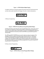
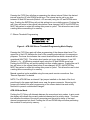
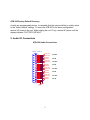
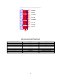
Broadcast Devices, Inc.
ATB-300 Audio Tool Box
*Digital/Analog Audio Switcher DA
Operations Quick Start Guide
Broadcast Devices, Inc.
2066 E. Main Street
Cortlandt Manor, NY 10567
Tel. (914) 737-5032
Fax. (914) 736-6916
World Wide Web: www.Broadcast-Devices.com
Rev D. 05/09
*Option Dependent
Table of Contents
I.
Basic Description
3
II.
ATB-300 Operational Mode Descriptions
A. Memory Programming
B. Silence Interval Programming
C. Silence Threshold Programming
3–7
4
4
5
III.
Remote Control Operation
7
IV.
Input Mode Selection Menu System
7-9
V.
Audio I/O Connector Diagrams
9 - 10
VI.
Remote Control Connector Diagrams
11
VII.
Warranty
12
2
I. Basic Description
Basic Description by model number:
ATB-300-1 4 – AES I/O Digital only switcher/router
ATB-300-2 4 – AES I/O and 4 -analog L/R input switcher/router
ATB-300-3 4 - AES I/O and 4 - analog L/R output switcher/router
ATB-300-4 4 – Analog only I/O
ATB-300-5 4 - AES I/O, 4 – analog L/R balanced I/O
ATB-300-6 8 – AES I/O
ATB-300-7 8 – Analog Input 4 Analog Output
ATB-300-8 8 – Analog I/O
ATB-300 DAS – Special Configuration for use with Digital Alert Systems DASDEC EAS
System – 4 individual A/B switchers AES and or Analog I/O – Call for configuration
information
ATB-300 is a 4 or 8 channel stereo analog / digital audio switcher featuring silence
detection and automatic switching. Input and output types are defined by the model
number as shown above. The ATB-300 can be used to manually switch inputs or will
automatically switch when a programmable silence interval of between 30 and 600
seconds is detected. Auto switching is programmed using a “priority list” of 4 or 8
memories depending on configuration which are programmed with input channels to
search for audio in order of preference. The ATB-300's intelligent search algorithm
constantly monitors the inputs to allow immediate switching to the first active channel in
the priority list without need to sequence through inactive channels when silence.
II. ATB-300 Operational Mode Descriptions
ATB-300 Manual Mode
The ATB-300 defaults to MANUAL mode upon power up. The LCD display will indicate
the manual mode as well as the currently selected input channel and the active /
inactive status of that input on the top line. The lower line indicates the channel that will
be switched to the outputs when the green ENTER (check mark) key is pressed. The
UP and DOWN arrows are used to select the input channel. The activity status of that
channel is also shown to avoid switching to an inactive channel. When the select key is
pressed the new selection is stored to memory and the audio is switched. This setting is
NON VOLATILE. If the ATB-300 is power cycled this channel will be selected on power
up.
3
Figure 1 - ATB-300 Manual Mode Display
In manual mode the user may also program the priority memories, the silence interval
and the relative audio threshold which triggers the active / inactive determination.
M A NU A L CH1 SELECTED
I NPU T: CH 1 NO A U DI O
A. Memory Programming
PRI 1 CH 1 NO A U DI O
I NPU T: CH 1 NO A U DI O
Figure 2 - ATB-300 Priority Memory Programming Mode Display
Pressing the F2/F5 key will enter the memory programming mode. In this mode, the top
line of the LCD indicates the current memory (PRI 1 to PRI 8) being programmed, its
contents and the activity status of that channel. The lower line indicates the channel that
will be programmed into the memory when the ENTER key is pressed along with its
activity status.
The LEFT and RIGHT ARROW keys are used to select a memory to program. The
UP and DOWN keys sequence through the input channel selections. Pressing the
ENTER key will program the channel indicated on the bottom line in to the priority
memory. Note that programming the same channel into more than one memory is
possible and can be done to avoid having an unconnected input in the priority memory
list. The factory default memory channels are programmed to sequence through the 8
possible inputs in numerical order.
B. Silence Interval Programming
A U DI O LOSS TI M EOU T
SECONDS = 60
Figure 3 - ATB-300 Silence Interval Program Mode Display
4
Pressing the F3/F6 Key will allow programming the silence interval. Select the desired
interval using the UP and DOWN arrow keys. The interval can be set to any time
between 30 and 600 seconds (Default = 60 seconds) using the UP and DOWN arrow
keys. Pushing the ENTER key will put this setting into non-volatile memory. Pushing the
red X key will return to the original value before it was changed. NOTE: the ENTER key
MUST be pushed to retain this setting after power is cycled. This allows the user to test
a setting before committing it to memory.
C. Silence Threshold Programming
OU TPU T LEV EL = 341
SI LENCE LEV EL = 5
Figure 4 - ATB-300 Silence Threshold Programming Mode Display
Pressing the F3/F6 Key again will allow programming of the silence detect level. The
upper line of the LCD indicates the level of the currently selected input for comparison
purposes. The lower line indicates the current threshold below which a channel will be
considered INACTIVE. The relative level can be set to any time between 1 and 100
(Default = 5 = - 40 dB below nominal input) using the UP and DOWN arrow keys.
Pushing the ENTER key will put this setting into non-volatile memory. Pushing the red X
key will return to the original value before it was changed. NOTE: the ENTER key
MUST be pushed to retain this setting after power is cycled. This allows the user to test
a setting before committing it to memory.
Manual operation is also available using the rear panel remote connections. See
“Remote Operation” for details
NOTE: The ATB-300 has an internal 2 pin jumper installed on the back of the front
panel board in the upper right hand corner near the power connector. Removing this
jumper will disable front panel programming of the silence detect time and activity
threshold to prevent unauthorized changes.
ATB-300 Auto Mode
Pushing the F1/F4 key will alternate between the manual and auto modes. In auto mode
the display will indicate the currently selected channel and its activity status. The lower
line indicates the status of the priority memories and the activity status of the input
channel programmed into them. Pushing the UP and DOWN keys will allow previewing
the contents of each priority memory.
5
A U TO CH1 A U DI O OK
PRI 1 CH 3 NO A U DI O
Figure 5 - ATB-300 Auto Mode Display
When the ATB-300 detects an audio level below the silence threshold for the pre
selected time interval it will look at the priority memories and switch the lowest priority
channel which is active to the output. The display will indicate a loss of audio on the top
line of the LCD and will indicate the input which was switched to the output on the lower
line along with its activity status. It will also close the fault detected relays contacts
available on the rear panel remote connector. Pushing the red X key will reset the
warning as well as the relays. If the rear panel remote is enabled, an input is provided to
do this using an external closure as well.
A U DI O LOSS DETECTED
A U TO CH 5 A UDI O OK
Figure 6 - ATB-300 Silence Detected Display
Note that the ATB-300 is capable of detecting a subsequent loss of audio on the
channel that was automatically selected. If such an event should occur, the priority list
will again be used to select the first available active channel in the list.
Audio Restored Look Back Feature
The ATB-300 has the ability to monitor the designated primary channel after a loss of
audio has been detected by the silence sensor if the unit is in the automatic mode. If
audio is restored to the primary channel after a user programmed number of minutes
the unit will revert back to the primary channel automatically.
The factory default setting for the look back feature is disabled. To enable the look back
feature follow the procedure below:
1. Place the unit in the manual mode by pressing F1
2. Toggle F3 until the display says AUTO RETURN FUNCTION – factory default is
DISABLED.
3. Press the UP arrow to set the number of minutes the unit should wait before
reverting back to the primary channel only after audio has been restored to the
primary channel. The unit can wait from 1 to 60 minutes before reverting back to
the primary channel.
6
4. Place the unit back into the AUTO mode by pressing F1 twice. The first press of
F1 takes the unit out of the programming mode and into MANUAL. The second
press of F1 places the unit back into AUTO mode.
III. REMOTE CONTROLLED OPERATION
The ATB-300 provides remote inputs to select between manual and auto modes, reset
a fault warning, selection of an input and to enable/disable remote operation. Open
collector status outputs are provided to indicate the currently selected input channel.
These outputs are capable of sinking up to 100ma and are rated at a maximum of 30v
DC.
To enable remote operation the REMOTE ENABLE input must be connected to the
remote common (ground). Refer to page 9 “ATB-300 Remote Connections” diagram for
connection information.
The REMOTE AUTO or REMOTE AUTO inputs are used to select the switching mode
by connecting the desired mode selection pin to remote common momentarily. To
enable remote channel selection, the ATB-300 must be in MANUAL mode.
When the ATB-300 is in MANUAL mode, connecting a remote channel select input to
remote common momentarily will cause the corresponding input to be selected as the
current output. ONLY ONE channel select input can be active. If more than one input is
selected simultaneously the ATB-300 will not switch.
IV. Input Mode Selection Menu Operation
The ATB-300 inputs can be configured for mode of operation on an individual basis.
Stereo, Mono Left, Mono Right, L+R and Stereo Swap can be configured from the front
panel. Use mono left and mono right to fill in a missing channel. For example; choosing
mono left will take a signal only input on the left channel and apply it to both channels at
the output of the unit. Use L+R to create a monaural input from a stereo source.
To select the input mode push F4 once. The display will indicate that you are in the
INPUT MODE SELECTION menu. Select the input channel pair (1-8) using the up and
down arrow keys. The left and right arrow keys are then used to select between the
following modes:
7
Press F4 once: Input Mode Selection
Pushing the up arrow/down allows you to select the input channel to be changed:
Pushing the left/right arrow buttons allows selection of the following input modes:
OFF
Stereo - Factory Default
LR Swap - L/R Channels Swapped
Mono L - L input fed to both L & R outputs
Mono R - R input fed to both L & R outputs
L + R - L & R inputs are summed and fed to both L & R outputs.
The input mode is automatically saved when selected. To exit this menu
press the F1 key to return to the main menu.
Press F4 twice: Input Invert Control – Phase Inversion
Pushing the up arrow/down allows you to select the input channel to be changed:
Pushing the left/right arrow buttons allows selection of the following input modes:
Normal
Invert Left
Invert Right
Note: Phase inversion is Left or right but not both simultaneously.
Input Invert Control modes are automatically saved when selected. To exit this menu
press the F1 key to return to the main menu.
Press F4 three times to enter Input Gain Control menu
Pushing the up arrow/down allows you to select the input channel to be changed:
Pushing the left/right arrow buttons allows you to adjust gain in one dB increments +/10 dB
Press F4 four times and the display will indicate Output Gain Control
Pushing the up arrow/down allows you to select the output channel to be changed:
Pushing the left/right arrow buttons allows you to adjust gain in one dB increments +/10 dB
Factory default for input and output gain controls is 0 dB. When factory default gains are
used AES3 I/O is unity. When AES3 inputs are output to an analog channel the analog
output will correspond to –10 dB below full scale AES3 input when AES3 input is
nominal – 10 dB below full scale.
8
ATB-300 Factory Default Recovery
As with any programmable device, it is possible that the user would like to quickly return
to the “factory default” settings. To return the ATB-300 to its factory configuration
remove AC power to the unit. While holding the red “X” key, restore AC power until the
display indicates “FACTORY DEFAULT”.
V. Audio I/O Connections
ATB-300 Audio Connections
DIGITAL AUDIO I/O
1
14
2
15
3
16
4
17
5
18
6
19
7
20
8
21
9
22
10
23
11
24
12
25
13
AESOUTP4
AESOUTN4
CH4 OUT
AESINP4
AESINN4
CH4 IN
AESOUTP3
AESOUTN3
CH3 OUT
AESINP3
AESINN3
CH3 IN
AESOUTP2
AESOUTN2
CH2 OUT
AESINP2
AESINN2
CH2 IN
AESOUTP1
AESOUTN1
CH1 OUT
AESINP1
AESINN1
CH1 IN
DB-25
9
ANALOG AUDIO - INPUT & OUTPUT PINOUTS ARE IDENTICAL
1
14
2
15
3
16
4
17
5
18
6
19
7
20
8
21
9
22
10
23
11
24
12
25
13
CH8P
CH8N
CH8 RIGHT
CH7P
CH7N
CH8 LEFT
CH6P
CH6N
CH 7 RIGHT
CH5P
CH5N
CH 7 LEFT
CH4P
CH4N
CH 6 RIGHT'
CH3P
CH3N
CH 6 LEFT
CH2P
CH2N
CH5 RIGHT
CH1P
CH1N
CH5 LEFT
DB-25
ATB-300 AUDIO INPUT MAPPING
INPUT CHANNEL
1
2
3
4
5
6
7
8
TYPE
DIGITAL
DIGITAL
DIGITAL
DIGITAL
ANALOG
ANALOG
ANALOG
ANALOG
10
LOCATION
AES 1
AES 2
AES 3
AES 4
ANALOG IN 1-2 (L/R)
ANALOG IN 3-4 (L/R)
ANALOG IN 5-6 (L/R)
ANALOG IN 7-8 (L/R)
VI. Remote Control Connections
ATB-300 Remote Connections
REMOTE P1
1
14
2
15
3
16
4
17
5
18
6
19
7
20
8
21
9
22
10
23
11
24
12
25
13
INPUT COM
INPUT COM
INPUT COM
INPUT COM
INPUT COM
INPUT COM
INPUT COM
+12V
CHASSIS
DB-25 FEMALE (USER SUPPLIED)
SELECT-INPUT1
STATUS1
SELECT-INPUT2
STATUS2
SELECT-INPUT3
STATUS3
SELECT-INPUT4
STATUS4
SELECT-INPUT5
STATUS5
SELECT-INPUT6
STATUS6
SELECT-INPUT7
STATUS7
SELECT-INPUT8
STATUS8
REMOTE P2
1
14
2
15
3
16
4
17
5
18
6
19
7
20
8
21
9
22
10
23
11
24
12
25
13
K1-COM
K1-NC
K1-NO
K2-COM
K2-NC
K2-NO
FAULT DETECTED RELAYS
AUTO
AUTO-COM
MANUAL
MANUAL-COM
REMOTE ENABLE
REMOTE ENABLE COM
FAULT RESET
FAULT RESET COM
REMOTE INPUTS
CHASSIS
DB-25 MALE (USER SUPPLIED)
Notes:
1. Status outputs are open collector Darlington transistors capable of sinking
100ma @ 30v DC.
2. Select and remote inputs are momentary closures with internal 4.7K pullup
resistors to 5v DC.
11
VII. Warranty
Broadcast Devices, Inc. products are warranted against failure due to faulty materials
or workmanship for a period of one year from the date of shipment to the ultimate user.
The warranty covers repair or replacement of defective parts at the factory, provided the
unit has been returned prepaid by the user. All shipments to the factory shall have
affixed to the outside of the container a return authorization number obtained from the
factory. The above warranty is void if the unit has been modified by the user outside of
any recommendations from the factory or if the unit has been abused or operated
outside of its electrical or environmental specifications. If customer conducted field tests
suggest that the unit may be faulty, whether or not the unit is in warranty, a full report of
the difficulty should be sent to Broadcast Devices, Inc. factory at Cortlandt Manor, New
York. The office may suggest further tests or authorize return for factory evaluation.
Units sent to the factory should be well packed and shipped to Broadcast Devices,
Inc. 2066 E. Main Street, Cortlandt Manor, NY 10567. Remember to affix the R.A.
number to the outside of the carton. Any packages received without such R.A. number
will be refused. Note: freight collect shipments will also be refused. When the unit has
been received, inspected and tested, the customer will receive a report of the findings
along with a quotation for recommended repairs, which are found falling outside of the
standard warranty. Units returned for in-warranty repairs, which are found not to be
defective will be subject to an evaluation and handling charge. In-warranty units will be
repaired at no charge and returned via prepaid freight.
Out-of-warranty units needing repair require a purchase order and will be invoiced for
parts, labor, and shipping charges.
When ordering replacement part, always specify A) Part Description, and Quantity; B)
Date of Purchase, Where Purchased; C) Any Special Shipping Instructions. Always
specify a street address, as shipping companies cannot deliver to a postal box.
Broadcast Devices, Inc. is not responsible for any other manufacturer’s warranty on
original equipment. Nor are we responsible for any failure, damage, or loss of property
that may occur due to the installation or operation of our equipment outside of
recommended specifications.
Broadcast Devices, Inc. reserves the right to change materials, specifications, and
features from time to time.
www.broadcast-devices.com
Broadcast Devices, Inc.
2066 E. Main Street
Cortlandt Manor, NY 10567
Email: [email protected]
(914) 737-5032 Tel. (914) 736-6916 Fax.
12
13
14