1
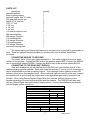
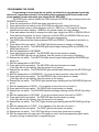
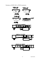
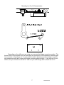
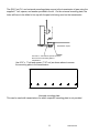
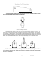
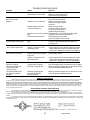
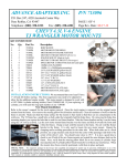
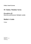
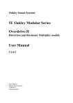
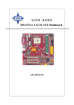
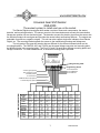
Universal Gear Shift Sender
GSS-2000
The easiest system to install and use on the market.
The Dakota Digital universal gear shift sender consists of three main components; the sensor,
decoder, and mounting brackets. The sensor mounts to the transmission and converts the transmission
linkage arm position into an electrical signal. The decoder converts the electric signal from the sensor into
the individual outputs for each gear and provides the neutral safety and backup features. The outputs are
selectable for positive or negative outputs. This unit can also support single-wire indicators from Dakota
Digital, Inc. The mounting brackets attach the sensor to the transmission housing and linkage arm.
The only parts of the gear shift sender that are different for the different transmissions are the
mounting brackets. The GM 350, 400, and 700-R4 use the same linkage connector and mounting plate,
but different holes in the mounting plate. The Ford C-6 and C-4 each have different mounting plates and
linkage connectors. For other transmissions, a universal mounting plate is provided.
Dakota Digital
DIM
PARK
REVERSE
NEUTRAL
OVERDRV
DRIVE
SECOND
FIRST
1-WIRE
RED
GREEN
BLACK
BACKUP
POWER
GROUND
SAFETY
GSS-2000 DECODER
Programming LEDs
Programming Switch
B.U. PWR GND N.S.
SW
to sensor BLACK wire
to sensor GREEN wire
to sensor RED wire
To back-up lights (optional)
fused +12V with key in 'ON'
and 'START' positions
to Chassis Ground
To ECM Park-Neutral input (optional)
To neutral safety relay (optional)
TYPE OF INDICATOR SYSTEM
DIM
PARK
REVERSE NEUTRAL
OVRDRV
DRIVE
SECOND
FIRST
INDIVIDUAL PARKING
LIGHTS
BULBS
STR
NOT
PARK
REVERSE NEUTRAL OVRDRV
DRIVE
SECOND
FIRST
USED
TERMINAL TERMINAL TERMINAL TERMINAL TERMINAL TERMINAL TERMINAL
SYSTEM
RED
WIRE (+)
RED
WIRE (+)
RED
WIRE (+)
RED
WIRE (+)
RED
WIRE (+)
RED
WIRE (+)
RED
WIRE (+)
1-WIRE
NOT
USED
NOT
USED
DGS-1
PARKING
LIGHTS
GREEN
WIRE (+)
GRAY
WIRE (+)
PURPLE
WIRE (+)
YELLOW
WIRE (+)
ORANGE
WIRE (+)
BLUE
WIRE (+)
BROWN
WIRE (+)
NOT
USED
DGS-2
NOT
USED
GREEN
WIRE (+)
GRAY
WIRE (+)
PURPLE
WIRE (+)
YELLOW
WIRE (+)
ORANGE
WIRE (+)
BLUE
WIRE (+)
BROWN
WIRE (+)
NOT
USED
NOT
USED
NOT
USED
NOT
USED
NOT
USED
NOT
USED
NOT
USED
NOT
USED
GEAR
TERMINAL
NOT
USED
NOT
USED
NOT
USED
NOT
USED
NOT
USED
NOT
USED
NOT
USED
White/Green
WIRE
NOT
USED
NOT
USED
NOT
USED
NOT
USED
NOT
USED
NOT
USED
NOT
USED
YELLOW
WIRE
PURPLE
WIRE (-)
YELLOW
WIRE (-)
BLUE
WIRE (-)
GREEN or
WHITE
NOT
USED
VFD/VHX
NOT
USED
SYSTEM
ODYR/SLX
NOT
USED
GAUGE
DGS-3
NOT
USED
DGS-4
LOKAR
PARKING
LIGHTS
(- OUT)
1
BROWN or ORANGE WHITE or
NOT USED or BROWN ORANGE
MAN# 650023B
PARTS LIST
description
gear shift decoder
relay for neutral safety
gear shift sender with 10’ cable
long gear shift sender arm
spacer (7/16” hex nut)
5/16” x 1” bolt
5 1/4” rod
4 1/4” rod
3 1/4” rod
1/8” retainer clips for rods
GM mounting plate
GM linkage connector
C-4 mounting plate
C-4 linkage connector
C-6 mounting plate
C-6 linkage connector
universal mounting plate
quantity
1
1
1
1
2
2
1
1
1
6
1
1
1
1
1
1
1
The neutral safety and backup light features do not have to be connected for gear sender to
work. These are optional features provided for vehicles which do not already have these
provisions.
CONNECTING SENSOR TO DECODER
The sensor has a 10 foot gray cable attached to it. This cable contains three wires which
connect to the decoder. Connect the RED wire to the terminal marked RED Connect the GREEN
wire to the terminal marked GREEN. Connect the BLACK wire to the terminal marked BLACK.
CONNECTING TO THE GEAR SHIFT DISPLAY
Gear shift displays are not included with the GSS-2000, but it will interface with all of the
standard display systems available. Each gear output will provide 12 volts at up to 0.3 amperes or
can be programmed to provide grounding outputs. This is enough current capacity for any LED
indicator or low power incandescent bulbs. When individual lights are used for each gear, connect
the negative wire to ground and the positive wire to the appropriate gear output terminal on the
decoder. When using Dakota Digital’s Digital Gear Shift Indicator connect the wires to the
decoder according to the instructions provided with the indicator. The GSS-2000 will also work
with any Dakota Digital vacuum florescent display system. Connect wires between the decoder
and the display system control box.
GSS-2000 Specifications
SUPPLY
Voltage Input (+12) Range
5.6 to 22 V
INPUTS
DIM Off DIM On
DIM
< 1.6 V
> 4.0 V
OUTPUTS
Output Current
Gear Output
< 0.3 A
BACKUP
< 15 A
CURRENT DRAW
Park-Neutral Reverse
Drive
W/O Safety Relay
≈ 30 mA
≈ 80 mA ≈ 20 mA
W/ Safety Relay
≈ 160 mA
≈ 80 mA ≈ 20 mA
2
MAN# 650023B
PROGRAMMING THE GEARS
Programming is done using the set switch, small switch on the decoder located by
the sensor connection terminals, and watching the programming LED’s(not visible until
power applied) located near each gear output on the GSS-2000.
The PARK light is directly behind the PARK terminal, REVERSE light is directly behind the
REVERSE terminal, etc.
1. Place the transmission in PARK and make sure the key is off.
2. Press and hold the set switch on the GSS-2000 decoder while turning the key on.
3. The lights should come on either all green or all red. RED is for +12V outputs for Dakota
Digital and most other displays. GREEN is for ground outputs for Lokar displays.
4. Press and release the switch to change the output type, toggle from RED or GREEN LEDs lit.
Press and hold the switch, for about 4 seconds, until both RED and GREEN LEDs turn on to
save the setting. Release the switch and begin gear programming.
5. The PARK lights should be flashing between RED and GREEN. (Transmission should be in
PARK)
6. Press and hold the set switch. The PARK light should remain on steady, not flashing.
7. Release the set switch. The REVERSE lights should begin flashing RED and GREEN; The
PARK light will go out.
8. Shift the transmission to REVERSE.
9. Press and hold the set switch. The REVERSE light should remain on steady.
(If the REVERSE light will not quit flashing, then the sensor is not turning or following.)
10. Release the set switch. The NEUTRAL lights should begin flashing and the REVERSE light
will go out.
11. Shift the transmission to NEUTRAL.
12. Press and hold the set switch. The NEUTRAL light should remain on steady.
(If the light will not quit flashing, then the sensor is not turning.)
13. Release the set switch. The OVERDRIVE lights should begin flashing and the NEUTRAL light
will go out.
14. Shift the transmission to OVERDRIVE. (If you do not have overdrive, then shift to DRIVE.)
15. Press and hold the set switch. The OVERDRIVE light should remain on steady.
(If the light will not quit flashing, then the sensor is not turning.)
16. Release the set switch. The DRIVE lights should begin flashing and the OVERDRIVE light will
go out.
17. Shift the transmission to DRIVE. (If it is already in drive, then do not move it.)
18. Press and hold the set switch. The DRIVE light should remain on steady.
19. Release the set switch. The SECOND lights should begin flashing and the DRIVE light will go
out.
20. Shift the transmission to SECOND. (If you do not have second, then shift to FIRST.)
21. Press and hold the set switch. The SECOND light should remain on steady.
(If the light will not quit flashing, then the sensor is not turning.)
22. Release the set switch. The FIRST lights should begin flashing and the SECOND light will go
out.
23. Shift the transmission to FIRST. (If it is already in first, then do not move it.)
24. Press and hold the set switch. The FIRST light should remain on steady.
25. Release the set switch. The FIRST light will go out and then come back on steady.
26. Shift the transmission through each of the gears to verify that the programming lights match
correctly, turning on steady when in appropriate gear.
3
MAN# 650023B
CONNECTING THE NEUTRAL SAFETY RELAY
If your vehicle already has a neutral safety switch in the wiring harness to prevent the
vehicle from starting while it is in gear, then you do not need to connect this neutral safety switch.
Otherwise, cut the wire that goes from your starter switch to the starter solenoid. Connect
one end of the wire to the GREEN wire from the relay and connect the other end to the BLACK
wire from the relay. For wiring harnesses which provide wires for the neutral safety, connect one
side to the GREEN wire and the other side to the BLACK wire. The wire you cut and connect to
the relay should provide +12V to the starter solenoid when the ignition switch is in the start
position, which engages the starter motor.
The WHITE wire from the relay connects to the SAFETY terminal on the decoder. The
RED wire connects to the power wire for the decoder.
*For the neutral safety switch to operate properly, the POWER terminal on the
decoder as well as the red wire on the relay must have power when the key is in both the
run and start positions.
Ignition
Switch
Ignition
Switch
To Ignition Switch Starter Wire
Cut wire between starter solenoid and the
wire that feeds it from the ignition switch
do not connect
Wiring SAFTEY relay
GREEN
87
BLUE
30
RED
86
85
To POWER terminal on GSS-2000 Decoder
(there will be two wires in one terminal at decoder)
WHITE
To SAFETY terminal on GSS-2000 Decoder
BLACK
To Starter Solenoid
Starter
Solenoid
Starter
Solenoid
Typical starter wiring
Wiring after SAFTEY relay installed
CONNECTING PARK-NEUTRAL SIGNAL TO AN ECM
If your vehicle is fuel injected and the ECM requires a signal when the transmission is in
either park or neutral, the neutral safety terminal can be used. The SAFETY terminal provides a
ground when the transmission is in park or neutral. This can be connected to the ECM in order to
pass vehicle inspection.
The SAFETY terminal can be used for both a neutral safety and ECM signal at the same
time.
CONNECTING BACKUP LIGHTS TO THE GSS-2000
If your vehicle already has a backup light switch, then you do not need to connect anything
to the BACKUP terminal. If you do not have a backup switch and will be using backup lights on
your vehicle, then connect the “hot side” of the backup lights to the terminal marked BACKUP.
This circuit is designed to supply +12 V up to 15 amps when the transmission is in reverse.
4
MAN# 650023B
MOUNTING SENSOR TO TRANSMISSION.
The diagrams on the following pages show the mounting hardware used and mounting
location for the most common transmissions. For most applications, the sensor mounts to the side
of the transmission using a couple of the transmission pan bolts. A metal plate will attach to the
transmission linkage so that it rotates as the transmission is shifted. A rod with a couple of bends
in it connects the sensor arm to the plate on the transmission linkage. This allows the sensor arm
to move as the transmission is shifted through the gears. Each gear will correspond to a different
position for the sensor arm. It does not matter exactly where the sensor arm is when it is in park,
first or any other gear. Once the Decoder has been programmed it will remember the positions.
The Decoder converts these positions into separate a 12 volt or ground output for each gear.
If a Kugel adjustable shifter is being used, you will need a Kugel nut to attach the sensor to
the shift linkage. The Kugel nut is available from Dakota Digital, Inc.
As the transmission is shifted through all of the gears, the sensor arm should not hit either
of its stops, or get ‘bound’ or ‘hung up’. The arm which is mounted on the sender allows for a 1
3/4” throw with the outside hole and 1 5/16” throw with the inside hole. The longer arm which is
sent in the kit allows for throws from 3 1/2” with the outside hole to 2 3/16” with the inside hole.
When properly adjusted, the sensor arm will move through about 1/2 or more of its full travel. If
the sensor arm moves through less than 1/3 of its travel, it may be difficult for the decoder to
distinguish between gears. It does not matter which direction the sensor arm turns going from
Park to Low. Once the Decoder has been programmed it will read all of the gears correctly.
If the typical mounting location for the sensor will not work, the sensor can be mounted
anywhere that will allow the sensor arm to move as the gear shift selector moves. The sensor arm
can attach either at the transmission linkage or at the gear selector knob or anywhere in between.
A universal mounting plate is included to make custom fabrication easier. This plate has
several mounting holes for the sensor, but no holes for mounting the plate to the transmission. To
use this plate, first determine the best mounting location on your transmission and then mark and
drill holes into the universal plate to secure it. In most
instances the entire length of the plate will not be
needed and it can be cut down using a hack saw or
metal shears.
Approximate sender mounting location on transmission.
When moving or repositioning the sensor arm, be sure the slot in the center of the shaft is aligned with the arm as
shown here.
5
MAN# 650023B
Mounting to a GM 350, 400, or 700-R4 transmission.
6
MAN# 650023B
Mounting to a Ford C-6 transmission
Depending on the shifter you are using, you may use the linkage connector provided. The
bottom hole is for the sensor rod, the center hole is a pivot point for the connector, and the upper
hole connects to the linkage rod. A nylon cable tie can be passed around the linkage connector
and transmission shift arm to keep the linkage connector secured tightly. If this does not fit your
shifter, then you will need to drill an 1/8” hole into your shift linkage arm to attach the rod to.
7
MAN# 650023B
The GM, Ford C-6, and universal mounting plates secure to the transmission oil pan using the
supplied 1” bolt, spacer, and washer provided in the kit. On the universal mounting plate, the
holes will have to be drilled to line up with the pan bolts being used on the transmission.
transmission oil pan
Use 3/8" x 1" bolt and 3/8" spacer as shown
above to secure mounting plate to
transmission.
Use 5/16” x 1” bolt and spacer (7/16” nut) as shown above to secure
the mounting plate to the transmission
Universal mounting plate.
This can be used with transmissions for which a specific mounting plate is not provided.
8
MAN# 650023B
Mounting to a Ford C-4 transmission
This mounting plate connects to the lower two bolts of the four bolt plate located on the left
side of the transmission just behind the shift linkage arm.
Ford C-4 linkage connector.
Depending on the shifter you are using, you may use the linkage connector provided. The
bottom hole is for the sensor rod, the center hole is a pivot point for the connector, and the upper
hole connects to the linkage rod. A nylon cable tie can be passed through the two side holes and
around the linkage connector to keep the linkage connector secured tightly. If this does not fit your
shifter, then you will need to drill an 1/8” hole into your shift linkage arm to attach the rod to.
STANDARD ARM
LONG ARM
ARM FLIPPED
For the C-4 transmission the arm on the gear shift sender will need to be flipped around so
that it rotates on the bottom half. Make sure that the slot in the shaft is in line with the sender arm
as shown in the diagram.
9
MAN# 650023B
TROUBLE SHOOTING GUIDE
Problem
Cause
None of the lights will come on. Power wire not connected.
Ground wire not connected.
Always shows the same
gear or will not set
properly.
Indicator lights are all on
Except for the correct gear.
Reverse and Overdrive lights
are on at the same time.
Overdrive and Second lights
are on at the same time.
Overdrive, Neutral, and Drive
Lights are flashing.
The neutral safety relay
And unit just make
“clicking” sound.
The neutral safety does
not allow the starter to
engage.
Solution
Make sure +12 volt wire is connected.
Make sure the ground wire is
connected to a good ground.
Sensor wire not connected.
Make sure all three wires from
the sensor are connected.
Sensor arm not connected.
Make sure the sensor arm
moves as the gear selector
is moved.
Sensor linkage connector
Make sure the linkage
is stuck or bound up.
connector and sensor arm
move freely as the trans. is
shifted through the gears
Decoder is set for wrong output Repeat steps 1-4 in Programming the Gears
type.
on page 3 and select all red lights on.
Decoder has not been set.
See Programming the Gears
section on page 3 of the manual.
Decoder is set for wrong output Repeat steps 1-4 in Programming the Gears
type.
on page 3 and select the opposite light color.
(red or green).
Sensor ground wire open.
Check sensor wire connections.
Sensor is moving out of its
Loosen sensor arm set screw. Rotate the sensor
operating range.
shaft so that the slot in the end aligns with the
sensor arm. Retighten set screw. (see page 5)
Sensor RED wire open.
Check sensor wire connections.
Sensor signal wire is shorted
Check sensor cable.
to ground.
Sensor is moving out of its
Loosen sensor arm set screw. Rotate the sensor
Operating range.
shaft so that the slot in the end aligns with the
sensor arm. Retighten set screw. (see page 5)
Decoder settings are incorrect Reprogram the decoder.
or have been corrupted.
See the Programming The Gears section on page 3.
Decoder is losing power
Make sure PWR terminal has 12 volts when the key
is in both the on and start positions.
Decoder is losing power
when key is placed in
the start position.
Make sure PWR terminal has 12 volts when the key
is in both the on and start positions.
SERVICE AND REPAIR
DAKOTA DIGITAL offers complete service and repair of its product line. In addition, technical consultation is available to help you work through any questions
or problems you may be having installing one of our products. Please read through the Troubleshooting Guide. There, you will find the solution to most problems.
Should you ever need to send the unit back for repairs, please call our technical support line, (605) 332-6513, to request a Return Merchandise Authorization
number. Package the product in a good quality box along with plenty of packing material. Ship the product by UPS or insured Parcel Post. Be sure to include the RMA
number on the package, and include a complete description of the problem with RMA number, your full name and address (street address preferred), and a telephone
number where you can be reached during the day. Any returns for warranty work must include a copy of the dated sales receipt from your place of purchase. Send no
money. We will bill you after repair.
Dakota Digital Limited Lifetime Warranty
DAKOTA DIGITAL warrants to the ORIGINAL PURCHASER of this product that should it, under normal use and condition, be proven defective in material or
workmanship for the lifetime of the original vehicle it was installed in, such defect(s) will be repaired or replaced at Dakota Digital’s option.
This warranty does not cover nor extend to damage to the vehicle’s systems, and does not cover removal or reinstallation of the product. This Warranty does
not apply to any product or part thereof which in the opinion of the Company has been damaged through alteration, improper installation, mishandling, misuse, neglect, or
accident.
This Warranty is in lieu of all other expressed warranties or liabilities. Any implied warranties, including any implied warranty of merchantability, shall be limited
to the duration of this written warranty. No person or representative is authorized to assume, for Dakota Digital, any liability other than expressed herein in connection with
the sale of this product.
10
MAN# 650023B