1
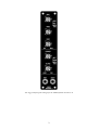
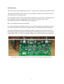
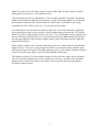
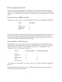
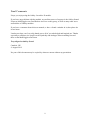
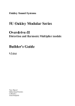
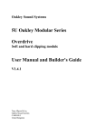
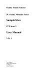
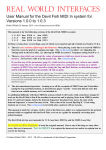
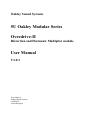
Oakley Sound Systems
5U Oakley Modular Series
Overdrive-II
Distortion and Harmonic Multiplier module
User Manual
V2.0.3
Tony Allgood
Oakley Sound Systems
CARLISLE
United Kingdom
The suggested front panel design for the MOTM format Overdrive-II
2
Introduction
This is the Project User Manual for the issue 1 Overdrive-II 5U module from Oakley Sound.
This document contains a basic overview of the module, a summary of its operation, and a
personal perspective from the author
For the Builder's Guide, which contain a basic introduction to the boards, a full parts list for
the components needed to populate the board or boards, and a list of the various
interconnections, please visit the main project webpage at:
http://www.oakleysound.com/overdrv.htm
For general information regarding where to get parts and suggested part numbers please see
our useful Parts Guide at the project webpage or http://www.oakleysound.com/parts.pdf.
For general information on how to build our modules, including circuit board population,
mounting front panel components and making up board interconnects please see our generic
Construction Guide at the project webpage or http://www.oakleysound.com/construct.pdf.
The prototype Overdrive-II module fitted to a natural finish Schaeffer MOTM format panel.
3
The 5U Overdrive Module
The Oakley Overdrive-II features two different waveform modifiers to produce a wide range
of overdriven and distortion sounds.
The first waveform modifier is a classic overdrive circuit which can produce a sound that is
familiar to many guitarists. Our original Overdrive 5U module, and the current Euro format
Overdrive module, contains just this part. The circuit has two basic modes selected by a
switch. Hard is a raucous distortion type effect useful for grunging up your signal. Soft is a
more subtle effect and produces a clean sounding overdriven amp sound.
Three front panel pots control the sound in this section. Drive controls the overall gain of the
circuit’s 'pre-amplifier' stage and essentially determines the level of overdrive or distortion.
Timbre is an effective tone control that cuts or accentuates the additional harmonics produced
by the pre-amplifier stage. And the Blend pot is essentially a wet/dry mix control that allows
you to add only as much of the effect as you want.
The second waveform modifier is a harmonic multiplier. This part of the module produces
additional harmonics by folding over the input signal so that the tops and bottoms of the
waveform are forced the wrong way. This produces strident changes in tone that are
dependant on the signal level. Up to two stages of symmetrical folding are available and at the
output there is a soft clipping circuit to prevent excessive folding at extreme input levels.
Two front panel pots affect the action of this circuit. Foldover adjusts the gain of the harmonic
multiplier and controls the amount of folding the input signal will be subjected to. The Balance
control is another wet/dry control so that you can mix the output of the overdrive circuit with
the harmonic multiplier.
The input/blend switch selects whether the input to the harmonic multiplier comes directly
from the input socket or the overdrive circuit. Thus the two modifiers in this module can be
operated in series or in parallel. In conjunction with the blend and balance pots you can create
a wide variety of different tones.
Voltage control is determined not within this unit, but as part of the signal chain placed before
this module. Using a voltage controlled amplifier module to control the signal level that is fed
into this unit will determine the strength of the overdrive, distortion or folding. Using a VCF
to alter the timbre of the signal fed to this module will control the overall harmonic level far
more than using a filter alone. In fact, hard sync type sounds can be easily obtained by simply
sweeping the filter's cut-off frequency.
The module accommodates either our standard Oakley/MOTM power header or a
Synthesizers.com power header.
4
Front panel controls
DRIVE – This controls the gain of the input stage to the gain boost circuit. The gain can be
varied from 5 to 55. The greater the gain the more the input signal will be distorted by the
overdrive circuitry.
HARD/SOFT – This switch controls whether the output of the gain boost circuit is clipped
hard, to produce a bright sound, or soft, to produce a more mellow form of distortion. Both
modes essentially prevent the output of the gain boost amplifier from reaching its theoretical
maximum. The hard mode truncates the waveform very sharply and quickly above a fixed
point. While the soft mode also restricts the output but the effects of the clipping are
introduced less quickly and the output is gently squeezed into submission.
TIMBRE – A classic guitar stomp box tone control. This simply cuts the high frequencies at
its minimum setting and boosts high frequencies at its maximum. In hard mode the timbre
control can make a lot of difference to the sound. Bear in mind that even in the middle
position the frequency response of the overdrive circuitry is not flat. The overall frequency
response is restricted to give this part of the module a typical boxy guitar amp sound.
BLEND – This pot is standard wet/dry mix control so that in the dry position it bypasses the
overdrive part of the circuit and allows you to hear the raw input signal. While in the wet
position you hear only that signal that has been processed by the overdrive circuitry. The blend
pot can be used as an overdrive depth control.
FOLDOVER – This essentially controls the signal level going into the harmonic multiplier. At
its minimum setting you would expect to get only small amounts of waveform distortion with
signals up to +/-5V peak. As the control is increased more and more of the signal is folded
back on itself until the folds themselves are folded back. Two stages of wavefolding are
possible with the pot at full and a signal level of at least +/-5V.
INPUT/BLEND – This determines whether the signal driving the harmonic multiplier comes
from the input socket or the output of the blend pot. In this way the harmonic multiplier can
be made to work in parallel (input) or in series (blend) with the overdrive circuitry. Note that
with the blend pot set to dry the switch will appear not to do anything.
BALANCE – This is a wet/dry pot that mixes the output of the overdrive's blend pot with the
output of the harmonic multiplier. Set to this pot to 'blend' and the blend pot to 'dry' to
completely bypass the module's effect circuitry.
5
Using the Oakley Overdrive – A Personal Perspective.
From 2007 when the original module was made available I have read many comments from
users regarding its usefulness. Probably more than any other Oakley module it has produced
the largest split of people who either loved, and still love it, and those that were profoundly
disappointed with it. Truthfully, I can't say I particularly enjoy receiving negative comments
but in some ways it is those negative comments that make one work harder to perfect any
design. The problem is that with some things it simply boils down to personal taste. I think the
original Oakley Overdrive is one such thing – it either produced a sound that you like or it
didn't. Furthermore, since the original did very little other than overdrive the input signal it is a
bit of a one trick pony. If you like the trick then all is well, if not, it's time to move on.
Nevertheless, it may be that the module is somewhat misunderstood. After all, the most
common criticism with the module is that it doesn't actually do much. In this perspective I
wish to argue the case for its defence. It actually does do a lot but it all depends on what sort
of signal you are putting into it.
Ignoring the harmonic multiplier section for the moment, the Oakley Overdrive in its overdrive
mode, is quite simply a derivative of a famous overdrive guitar pedal. This highly popular
pedal has been around for many years and it is widely copied. Several years ago I made up my
own stomp box version of it. Initially, driven from a 9V battery, then later from a 9V wallwart,
I pretty much slavishly copied the original's circuit. Later still I modified the main gain stage
and then added a hard clipping circuit (the distortion mode). I used this for many years with
my SH-101 and SH-1 and it's pretty much the plaintive solo sound on my own music albums.
The Oakley Overdrive's primary gain boosting circuit uses very similar circuitry to my
prototype pedal. The basic circuit topology remained the same but I changed the design to
allow it to run from a split power supply. I was careful to recreate the same voltage limits as in
the 9V design as I was keen to replicate the op-amp's saturated output characteristics. I also
tailored the gain stages to be more responsive to the levels seen in a modular synthesiser.
The key thing about using this part of the module is to not use any signal that has a high
harmonic content. Indeed, inserting a raw square wave into it will do nothing. Overdriving a
square wave simply produces another square wave. The tone control may have an effect but it
probably won't lead to an increase in distortion. Inserting a sawtooth will also have little effect.
In fact it is more likely in this case that the sound is dulled – the sawtooth waveform would be
turned into something more square wave like and therefore less harmonics would result. None
of these things are perhaps what we would look for in a distortion unit.
Therefore to get the best out of the unit, when playing just single notes at one time, it is
important that the input signal should have a relatively low number of harmonics.
Where the Overdrive section shines is when you use the module after a filter - especially one
set to relatively high resonance. The filter will select certain harmonics and the overdrive
module will accentuate these still further. So much so that the harmonic's frequency will
dominate over the fundamental. The effect is similar to the classic Moog Prodigy sync sound
when sweeping the frequency of a slaved VCO. And overdriving a simple one VCO - one VCF
arrangement is used frequently with the TB303 to give those rasping squealing acid lines.
6
However, it can be also used more subtly on more mellow filter sweeps with the overdrive
adding gentle overtones to a solo synthesiser lead.
The actual input level is very important too. The Overdrive module will produce much more
strident results when the input level approaches 5V peak. If the input signal is too weak then
the resultant overdriven effect will be much less. This means it is possible to get voltage
controlled overdrive effects if you use a VCA in front of the module.
It is traditional to have the distortion after the final VCA. In a fixed architecture synthesiser
this is generally the only way you can do it. But I find that using it between the VCF and the
final VCA gives me right sounds for solo work. The VCF will naturally vary the signal level as
the cut-off changes and having the VCA last will ensure that any additional hiss produced by
the high gain amplifier in the overdrive module will be only heard along with the signal and
therefore drowned out.
More complex sounds, such as chords, drum loops and so on, will be far more effected than
simple notes too. The more varying frequencies that are present in the input signal the more
distorted the output will appear. Generally speaking if you are after subtle overdriven effects it
is best to keep the input signal to just a few harmonically related notes.
The Oakley Overdrive-II of course adds a further circuit to the mix. Again, this works more
obviously with input signals that are low in harmonics. However, it can do some incredible
things to more complex waveforms even square waves once they have been through the
Overdrive's timbre control.
7
Power supply requirements
The module requires plus and minus 15V supplies. The power supply should be adequately
regulated. The current consumption is about 25mA per rail. Power is routed onto the PCB by
a four way 0.156” MTA156 type connector or the special five way Synthesizers.com MTA100
header.
Power connections – MOTM and Oakley
The PSU power socket is 0.156” MTA 4-way header. This system is compatible with MOTM.
Power
Pin number
+15V
Module GND
Earth/PAN
-15V
1
2
3
4
The earth/pan connection has been provided to allow the ground tags of the jack sockets to be
connected to the powers supply ground without using the module’s 0V supply. Earth loops
cannot occur through patch leads this way, although screening is maintained. Of course, this
can only work if all your modules follow this principle.
Power connections – Synthesizers.com
The PWR power socket is to be fitted if you are using the module with a Synthesizers.com
system. In this case the PSU header is not fitted. The PWR header is a six way 0.1” MTA, but
with the pin that is in location 2 removed. In this way location 3 is actually pin 2 on my
schematic, location 4 is actually pin 5 and so on.
Power
Location number
Schematic Pin number
+15V
Missing Pin
+5V
Module GND
-15V
Not connected
1
2
3
4
5
6
1
2
3
4
5
+5V is not used on this module, so location 3 (pin 2) is not actually connected to anything on
the PCB.
If the PSU header is fitted then pins 2 and 3 of PWR are linked together. This connects the
panel ground with the module ground.
8
Final Comments
I hope you enjoy using the Oakley Overdrive-II module.
If you have any problems with the module, an excellent source of support is the Oakley Sound
Forum at Muffwiggler.com. Paul Darlow and I are on this group, as well as many other users
and builders of Oakley modules.
If you have a comment about this user manual, or have a found a mistake in it, then please do
let me know.
Last but not least, can I say a big thank you to all of you who helped and inspired me. Thanks
especially to all those nice people on the Synth-diy and Analogue Heaven mailing lists and
those at the Muffwiggler.com forum.
Tony Allgood at Oakley Sound
Cumbria, UK
© August 2012
No part of this document may be copied by whatever means without my permission.
9