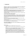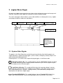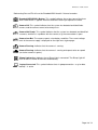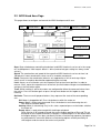
1
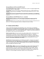
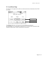
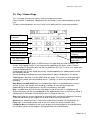
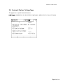
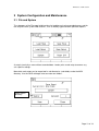
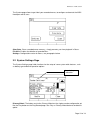
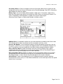
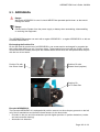
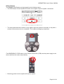
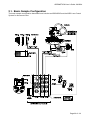
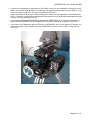
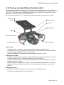
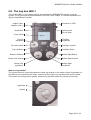
ARRI Gears 2.19D, 07/2011 ARRI Gears 1 2 Introduction ......................................................................................................................2 Jogbox Menu Pages ........................................................................................................3 2.1 System State Glyphs ................................................................................................3 2.2 ARRI Head Axes Page .............................................................................................5 2.3 Lens Motors Page ....................................................................................................7 2.4 Play / Record Page ..................................................................................................8 2.5 Contrast / Battery Voltage Page .............................................................................10 3 System Configuration and Maintenance.........................................................................11 3.1 File and System......................................................................................................11 3.2 System Settings Page: ........................................................................................... 12 4 Appendices ....................................................................................................................14 4.1 Prearrangement: ....................................................................................................14 4.2 Safety features: ......................................................................................................14 4.3 System Setup: ........................................................................................................14 4.4 Handwheel Adapter JHC-1: ....................................................................................14 4.5 Jogbox JBO-1:........................................................................................................14 Page 1 of 14 ARRI Gears 2.19D, 07/2011 1 Introduction ARRI Gears is a handy, easy to use and fast to setup remote control unit for the ARRI Head-2 and CLM-2 lens motors. The motion of the head and the lens motors can be recorded and played back immediately or can be saved for later playback. ARRI Gears is basically a standard ARRI Motion system with a simplified user interface on the controlling Jogbox. The ARRI Head can be controlled either directly with hand wheels attached to the head motors, by means of the Jogbox Handwheel Adapter JHC-1 or by means of an encoded fluid head. Gear ratio, maximum speed and acceleration can be set electronically. The internal encoders of the Encoded ARRI Head-2 provide simple and fast referencing methods for pan and tilt. The CLM-2 lens motors can be controlled hard-wired either by a WCU-3 (with ZMU-3), WHA2 (with WZU and WFU) or by a ZMU-1/2 (with FIU). For wireless control a UMC-3 can be connected. Cameras are not directly controlled by ARRI Gears. Nevertheless, a button in the play/record menu enables to start and stop most ARRI cameras. The remote emulation of the camera’s LCD menu (435 and ARRICam) and controlling buttons enable the check of the camera state and the remote change of speed and shutter settings (setting not possible on ARRICam ST and ARRICam LT). Video cameras can basically not be controlled. But the presence and run state of a video camera with timecode output can be indicated on the Jogbox. If appropriate for easier editing the first frame of every record/playback shot can be marked by means of a Bloop Light. In case of further questions about setup or operation please have a look at the appendices or the corresponding chapter of the ARRI Motion (AM) manual. Go through the ARRI Motion safety features (from the ARRI Motion manual) before you start operating the ARRI Gears. Application hints: • The mechanical gear on the ARRI Head has always to be set to 1. • Check that all breaks on the ARRI Head are released before you switch on the CHM-1 motors. • On the CHM-1 motors and on the Jogbox Handwheel Controller there are brake buttons which act on the corresponding hand wheel. If the system is tracking, but does not react on your hand wheels, check the state of the brake buttons. • If you are using a UMC-3 for wireless remote control all CLM-2 motors must still be plugged into the ARRI Motion systems LCB. In the mimic list the UMC-3 will be displayed as ZMU-3. The maximum control distance is somewhat lower compared to the standard UMC-3 application when motors are controlled by the UMC-3 directly. • Supply the AM system, the camera and your connected video equipment from the same power plug to avoid sparks due to small potential differences of different power lines. Page 2 of 14 ARRI Gears 2.19D, 07/2011 2 Jogbox Menu Pages On top of any Jogbox menu page there are riders which indicate the current active page and allow the selection of other pages by simply pressing the respective glyph. The small state glyphs which indicate system wide conditions are displayed on every Jogbox menu page (except on modal message boxes). Files Head Motors Lens Motors Play / Record Contrast / Supply State Glyph Area Special function indication of corresponding Jogbox Wheels / Buttons 2.1 System State Glyphs The glyphs in the State Glyph Area are blinking and non-blinking. Non-blinking glyphs are simple indications, whereas blinking glyphs (such as brake, emergency, battery) require user action before proceeding operation. Following there is a list of the most frequent displayed glyphs in ArriGears mode: Emergency Power Off: This symbol indicates that the EMERGENCY button has been pushed. Release the red emergency button and confirm your release by pressing the power on button on the CCB once again. Low Battery Warning: This symbol will blink when the incoming voltage is too low. What the exact warning level is depends on the Battery Type which can be set up in the System Settings (File – System – Settings screen). The actual battery voltage level is displayed on the right most Jogbox page. Encoded ARRIHEAD-2: This symbol indicates that an Encoded ARRI Head-2 has been connected and is communicating properly with the ARRIMOTION system. Page 3 of 14 ARRI Gears 2.19D, 07/2011 Referencing Pan and Tilt will use the Encoded ARRI Head-2 2 internal encoders. Encoded ARRIHEAD-2 Brakes: This symbol indicates that at least one of the three ARRI Head brakes is applied. Release the brakes before you operate the head. Camera OK: This symbol indicates that the system has detected and identified a camera, and the camera seems to be ready to run. Camera Not Ready: This symbol indicates that the system has detected and identified a camera, and there is a problem with the camera, e.g. the camera door is open. Camera Low Bat: The camera reports a low battery condition. The current voltage level of the camera supply is displayed on the right most Jogbox page. Camera Running: Indicates that the camera is running. Camera Running: Indicates that the camera is running and reports to be on speed (run led on camera is green). Bloop Light active: Indicates that a Bloop Light is connected. The Bloop Light will flash on the first frame of the move automatically. Laptop Connected: This symbol indicates that a Laptop connection – e.g. for data backup – is active. Page 4 of 14 ARRI Gears 2.19D, 07/2011 2.2 ARRI Head Axes Page This page allows to configure and control the ARRI Head pan and tilt axes. Files Head Motors Lens Motors Play / Record Contrast / Supply State Glyph Area Tracking On/Off On / Home Gear: Gear ratio between controlling hand wheel and ARRI Head axis can be set in the range of 5 to 800 percent. 100% equals about 1:1 drive (mechanical gear setting has always to be set to 1). Speed: The acceleration and speed of the respective ARRI Head axis can be set from 3 to 100 percent. Lower acceleration values result in smoother movements. Damp: Decreases the acceleration when an axis approaches a limit or end stop. Higher values result in smoother deceleration approaching the end stop. Limit: A press on a limit button sets the respective limit to the current position. In order to release a limit, move the respective axis to the limit (the limit button changes to a bold border) and press the limit button again. Track: While tracking is active the motors are configured to follow the command values from the mimics. Press this button again or press the top most button on the Jogbox to stop tracking. On/Home: These are multi purpose buttons, they represent the state of the corresponding axis. Off: Motor is plugged but off. Press the button to switch the motor on. Home: Motor is on but not referenced. Press the button to start referencing the axis. See different methods below. Homing: Motor is referencing. Only in this state a repeated press on the button switches the motor off. Ready: Motor is ready to be moved with tracking or playback. Since Version 2.19 instead of Ready the current angular position of Pan and Tilt are displayed on the respective buttons in degrees. A repeated press on the button while the angular display is on does not directly initiate a new homing sequence, but opens an advanced axis menu with different re-referencing options and the possibility to shift begin or end of move to the current axis position. Page 5 of 14 ARRI Gears 2.19D, 07/2011 Homing Methods with Encoded ARRI Head-2: If the Encoded ARRI Head-2 is properly connected to the system, the respective glyph will be displayed on top of the Jogbox pages. ArriHead Pan: The pan axis will find its reference position by means of ARRI Head internal encoders, it might move up to 180 degrees. The limits for pan movement are set to +/- three revolutions. ArriHead Tilt: The tilt axis will go towards tilt zero (horizontal) and perform a small repeated movement around the zero position. The limits for the tilt axis will be read from the ARRI Head electronics. Homing Methods with ARRI Head-2 (non - encoded): Set Reference: On the pan axis the current position will become the reference position without any movement of the axis. The limits for pan movement are initially set to +/- 3 revolutions. Overcurrent mid: The tilt axis will be driven to both mechanical end stops to find the limits for the tilt axis. The reference position will be set in between the two end stops. 2.3 Advanced Axis Menu There are two needs pleased by the advanced axis menu. The first one is the repeated referencing of a non-encoded ArriHead after a power cycle. The second one is the alignment of the camera for the replay of a move recorded on a different location. Whereas the repeated referencing of tilt is easy – tilt is usually simply horizontal – finding a new reference position for pan might be a little tricky and situation dependant. Home by motor index: An internal mark on the motor encoder, which is active only for one tick per motor axis revolution, allows the repeated homing of the pan axis – perfectly repeatable over power cycles as long as the gear slider stays in position 1 and the motor is not removed from the head. With the left and right buttons in the homing dialog the head can be move until a stop is accepted with Set. If the dialog will be exited without Set, the axis remains unreferenced (and therefore unmoveable). Set Reference: Repeated application of Set Reference might be a solution if your reference marks on the sets are of the kind of details in the background – e.g. a border of a building. First home the pan axis at an arbitrary position, only to make the head moveable by the hand wheels. Then center your mark on the camera display and set this position as new reference position by applying Set Reference again. Shift Data Begin / End: If you have to setup for replay on a new set and your only common feature is the start position of your move, it would be cumbersome to mess around with reference positions. In this case, reference your head, load your move to replay, spot the begin of your move through the camera and command Shift Data Begin. This will shift the begin of the preroll of your move to the current position (remember to start record with nonmoving axis so that the begin of the preroll matches the first frame position!). Page 6 of 14 ARRI Gears 2.19D, 07/2011 2.4 Lens Motors Page The controls on this page allow to switch on, reference and reverse the direction of the CLM-2 lens motors. Motor Direction On / Home The On/Home button acts in the same way as described for pan and tilt axis. After reversing an axis controlled by an absolute mimic (FIU, WZU, WFU) tracking has to be switched off and on again in order to reactivate the reversed axis. Page 7 of 14 ARRI Gears 2.19D, 07/2011 2.5 Play / Record Page This is the page for camera and play / record management control. Camera control is completely independent from the motion system and completely up to the user. The play and record buttons are very similar in their behaviour like simple tape recorders. Camera LCD Emulation Camera Start/Stop Goto Begin of Move Goto End of Move Play Record Progress Bar Area Stop Recording or Tracking Run/Stop Camera on button press Start Playback on button press Camera LCD Emulation works on ARRI cameras like operating the camera directly. The camera state (speed, shutter) is not interpreted or modified by the Gears system. Camera start/stop and LCD Emulation does not work on ARRICam ST and LT, in that case speed and shutter are displayed only. If configured in the System Setup play can be started/stopped by the Jogbox button close to the Secondary Wheel. During recording or playback the current time within the move is displayed on this button. Tracking works identical as on the ARRI Head axis page. The system has to be tracking to make the axes follow their commanding mimics. Tracking is a necessary precondition for recording. Goto Begin and Goto End buttons are enabled when there is a recorded move in memory and the system is on standby (not recording / tracking). All axes will go straight and independently to their target position, they will not follow any move path. Play is enabled when all axes are on either begin or end of the move. If configured in the System Setup play can be started/stopped by the Jogbox button close to the Primary Wheel. If a Bloop Light is connected it will be fired on the first frame of the move. Stop simply ends the current movement or recording state. Instead of the button on the touch screen the top button on the Jogbox can also be used to stop any movement. Record starts recording a move. Tracking has to be active to enable the record button. If a Bloop Light is connected it will be fired on the first frame of the newly recorded move. A Progress Bar on the bottom of the screen displays the current progress of recording within the available memory or the progress of playback within the recorded move. Page 8 of 14 ARRI Gears 2.19D, 07/2011 PL: The button next to the Primary Wheel (in the example above the top right button) can be configured to act like the play button on the touch screen (see File – system – setup). This option works only while the Play/Record page is visible and is indicated by the characters PL in the bottom line of the display. RS: The button next to the Secondary Wheel (in the example above the top left button) can be configured to act like the run camera button on the touch screen (see File – system – setup). This option works only while the Play/Record page is visible and is indicated by the characters RS in the bottom line of the display. Page 9 of 14 ARRI Gears 2.19D, 07/2011 2.6 Contrast / Battery Voltage Page This page has no specific control elements. LCD Display contrast can by adjusted by the right upper Jogbox wheel as long as this page is on screen. Page 10 of 14 ARRI Gears 2.19D, 07/2011 3 System Configuration and Maintenance 3.1 File and System The subpages of the File page hold functions for loading and saving recorded moves and for the setup of some system wide features, such as battery type and other operation options. A setup is basically a move without recorded data. Load a prior saved setup to recover any axis specific settings. Move data and setups can be organized in sub-directories (sub-folder) under the MOV directory. Use the SelDir dialogue also to create new folders. Select active directory Page 11 of 14 ARRI Gears 2.19D, 07/2011 The System page allows to get rid of your recorded moves, to configure and control the ARRI Head pan and tilt axes. Clear Data: Clears recorded move memory – simply prevents you from playback in Gears. File Utils: Enables the deletion of recorded files. Settings: Configuration center for Gears, see paragraphs below. 3.2 System Settings Page The System Settings page holds functions for the setup of some system wide features, such as battery type and other operation options. Low battery indication Primary Wheel: The button next to the Primary Wheel on the Jogbox can be configured to act like the Play button on the Play/Record page. See Play on Primary Wheel below to enable this option. Page 12 of 14 ARRI Gears 2.19D, 07/2011 Secondary Wheel: In Gears the button next to the Secondary Wheel on the Jogbox can be configured to act like the Camera R/S button on the Play/Record page. See RS on Secondary Wheel below to enable this option. Battery Type: Lets you configure different power supply types. If the power supply level is lower then the battery type specific threshold, the system refuses to start play or record. This state is indicated by a flashing battery symbol in the System State Glyphs. Selecting ‘Power Supply‘ as battery type disables all battery checks. OpMode Gears: If enabled this option lets you choose between ArriMotion and Gears mode. The selection will be taken into account on the next power up of the system. Reverse HW Adapter: If the Handwheel Adapter shall be operated by two persons (one on the wheels, another one on the Jogbox) from opposed sides of the Handwheel Adapter, Pan and Tilt handwheels have to change their role which will be accomplished by this option. Play on Primary Wheel: Enables the button next to the Primary Wheel on the Jogbox (configurable only with ArriMotion) to act like the play button while the Play/Record Page is visible. See the Play/Record page for the function indication. RS on Secondary Wheel: Enables the button next to the Secondary Wheel on the Jogbox (configurable only with ArriMotion) to act like the run/stop button on the camera while the Play/Record Page is visible. See the Play/Record page for the function indication. Speed Wheels: Forces the handwheels to act as speed command instead of a position command what results mainly in a little different behaviour at limits/end stops where the speed wheels have ‘no memory’. Page 13 of 14 ARRI Gears 2.19D, 07/2011 4 Appendices For easier reference and for illustration some selected pages from the ARRI Motion manual are supplied also as individual pdf - files. 4.1 Prearrangement For the very first usage of an ARRI Head-2 its position pins have to be changed to screws with 5.0mm pin diameter, please refer to the AM manual 5.1, p 120. If there is a need for remote power up of the system, a special cable for remote power on can be supplied. (see file A1_AH_position_pin.pdf) 4.2 Safety features There are different options to stop the system and to cut the power of the driving motors, please refer to the AM manual safety instructions, p. 8. (see file A2_safety_features.pdf) 4.3 System Setup See AM manual 2.1, page 22 for a summary of system components. (see file A3_system_setup_a.pdf, A3_system_setup_b.pdf and CO_310_2006_06_ARRIMOTION_STANDARD_CONFIGURATION.pdf) 4.4 Handwheel Adapter JHC-1 For the optional control via handwheel adapter see AM manual 5.10, page 140. (see file A4_JHC.pdf) 4.5 Jogbox JBO-1 For a description of the controlling Jogbox see AM manual 5.9, page 138. (see file A5_JBO.pdf) Page 14 of 14