1
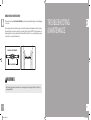
U7xe
U7x
U5x
U3xe
U3x
R7xe
R7x
R5x
R3xe
R3x
H7xe
H7x
H5x
H3xe
H3x
CYCLES OWNER’S MANUAL
bikes_om_r1.5.indd 1
9/9/11 8:19 AM
IMPORTANT PRECAUTIONS
SAVE THESE INSTRUCTIONS
Read this GUIDE before using the OWNER’S MANUAL. When using an electrical product, basic precautions should always be
followed, including the following: Read all instructions before using this product. It is the responsibility of the owner to ensure
that all users of this product are adequately informed of all warnings and precautions. If you have any questions after reading this
guide, contact Customer Tech Support at the number listed on the back panel of the OWNER’S MANUAL.
This product is intended for commercial use. To ensure your safety and protect the equipment, read all instructions
before operating.
2
bikes_om_r1.5.indd 2-3
3
9/9/11 8:19 AM
DANGER
TO REDUCE THE RISK OF ELECTRICAL SHOCK:
Always unplug the unit from the electrical outlet immediately after using, before cleaning, performing maintenance and putting on or
taking off parts.
CAUTION
If you experience any kind of pain, including but not limited to chest pains, nausea, dizziness, or shortness of breath, stop
exercising immediately and consult your physician before continuing.
WARNING
4
• Use this exercise bike for its intended purpose as described in this manual. Do not use attachments that have not been
recommended by the manufacturer.
• Never operate the exercise bike if it is not working properly, or if it has been damaged. Contact Customer Tech Support or the
authorized dealers for examination and repair.
• Do not use the exercise bike without proper footwear. NEVER operate the exercise bike with bare feet.
• Do not wear any clothing that might catch on any moving parts of this exercise bike.
• Keep hands and feet clear at all times from moving parts to avoid injury. Never turn the pedal cranks by hand.
• Do not dismount the exercise bike until the pedals are at a complete STOP.
• Do not attempt to ride the exercise bike in a standing position at high RPMs until you have practiced at slower speeds.
• Do not insert any object, hands or feet into any openings, or expose hands, arms or feet to the drive mechanism or other
potentially moving part of the exercise bike.
• Do not use any equipment that is damaged or has worn or broken parts. Use only replacement parts supplied by Customer Tech
Support or the authorized dealers.
• Do not operate where aerosol (spray) products are being used or when oxygen is being administered.
• Close supervision is necessary when used near children, invalids or disabled people.
• Ensure that adjustment levers (seat and handlebar fore-and-aft) are properly secured and do not interfere with range of motion
during exercise.
bikes_om_r1.5.indd 4-5
WARNING
TO REDUCE THE RISK OF BURNS, FIRE, ELECTRICAL SHOCK OR INJURY TO PERSONS:
••
••
••
••
••
••
••
••
••
••
••
••
Keep power cord away from heated surfaces. Do not carry this unit by its supply cord or use the cord as a handle.
Do not use other attachments that are not recommended by the manufacturer. Attachments may cause injury.
Use the unit only as described in the unit guide and owner’s manual.
Disconnect all power before servicing or moving the equipment. To clean, wipe surfaces down with soap and slightly damp cloth
only; never use solvents. (See MAINTENANCE)
The unit should never be left unattended when plugged in. Unplug from outlet when not in use, and before putting on or taking
off parts.
Do not operate under blanket or pillow. Excessive heating can occur and cause fire, electric shock, or injury to persons.
At NO time should pets or children under the age of 13 be closer to the unit than 10 feet.
At NO time should children under the age of 13 use the unit.
Children over the age of 13 or disabled persons should not use the unit without adult supervision.
Never operate the unit if it has a damaged cord or plug, if it is not working properly, if it has been dropped or damaged, or
immersed in water. Return the unit to a service center for examination and repair.
To disconnect, turn all controls to the off position, then remove plug from outlet.
Do not remove the console covers unless instructed by Customer Tech Support. Service should only be done by an authorized
service technician.
It is essential that your unit is used only indoors, in a climate controlled room. If your unit has been exposed to colder
temperatures or high moisture climates, it is strongly recommended that the unit is warmed up to room temperature before first
time use. Failure to do so may cause premature electronic failure.
5
9/9/11 8:19 AM
ELECTRICAL REQUIREMENTS
GROUNDING INSTRUCTIONS
Some of these products are designed to be self powered and do not require an external power supply source to operate. However,
these units can be AC powered. This will power the console at all times and requires no minimum RPM for operation.
This product must be grounded. If a unit should malfunction or breakdown, grounding provides a path of least resistance for electrical
current to reduce the risk of electrical shock. This product is equipped with a cord having an equipment-grounding conductor and a
grounding plug. The plug must be plugged into an appropriate outlet that is properly installed and grounded in accordance with local
codes and ordinances.
The Matrix cycles have different electrical requirements depending on the model chosen. The chart below should assist you with your
facility planning:
These units can be daisy-chained together, up to 4 units per dedicated 15 amp circuit, using a Matrix daisy-chain cord adapter
(sold separately).
DEDICATED CIRCUIT AND ELECTRICAL INFO
All Matrix units require the use of a 15 amp or 20 amp “dedicated circuit,” with a non-looped (isolated) neutral/ground, for the power
requirement. Quite simply this means that each outlet you plug into should not have anything else running on that same circuit. The
easiest way to verify this is to locate the main circuit breaker box, and turn off the breaker(s) one at a time. Once a breaker has been
turned off, the only thing that should not have power to it are the units in question. No lamps, vending machines, fans, sound systems,
or any other item should lose power when you perform this test.
Non-looped (isolated) neutral/grounding means that each circuit must have an individual neutral/ground connection coming from it,
and terminating at an approved earth ground. You cannot “jumper” a single neutral/ground from one circuit to the next.
In addition to the dedicated circuit requirement, the proper gauge wire must be used from the circuit breaker box, to each outlet that
will have the maximum number of units running off of it. If the distance from the circuit breaker box, to each outlet, is 100 ft or less,
then 12 gauge wire may be used. For any distance greater than 100 ft from the circuit breaker box to the outlet, 10 gauge wire must
be used.
DANGER
Improper connection of the equipment-grounding conductor can result in a risk of electric shock. Check with a qualified
electrician or serviceman if you are in doubt as to whether the product is properly grounded. Do not modify the plug provided
with the product. If it will not fit the outlet, have a proper outlet installed by a qualified electrician.
This product is for use on a nominal 110-120 Volt circuit and has a grounding plug. Make sure that the product is connected to an
outlet having the same configuration as the plug. No adapter should be used with this product.
This product must be used on a dedicated circuit. To determine if you are on a dedicated circuit, shut off the power to that circuit and
observe if any other devices lose power. If so, move devices to a different circuit.
WARNING
Connect this exercise product to a properly grounded outlet only.
Never operate product with a damaged cord or plug even if it is working properly. Never operate any product if it appears
damaged, or has been immersed in water. Contact Customer Tech Support for replacement or repair.
6
bikes_om_r1.5.indd 6-7
7
9/9/11 8:19 AM
BASIC OPERATION
8
bikes_om_r1.5.indd 8-9
9
9/9/11 8:19 AM
LOCATION OF THE EXERCISE BIKE
Place the exercise bike on a level and stable surface. There should be 3 feet of clearance
behind the exercise bike, 3 feet on each side and one foot in front for the power cord.
Do not place the exercise bike in any area that will block any vent or air openings. The
exercise bike should not be located in a garage, covered patio, near water or outdoors.
1 ft
31 cm
3 ft
3 ft
92 cm
92 cm
WARNING
Never operate product if it has a damaged cord or plug, if it is not working
properly, if it has been damaged, or immersed in water. Contact Customer Tech
Support for examination and repair.
3 ft
92 cm
RECUMBENT SEAT HEIGHT
To adjust the seat height on the Recumbent Cycle, locate the yellow lever under the right side of the seat before you mount the
Cycle. Place your right hand on the orange adjustment handle under the right side of the seat. Place feet on the ground while seated
and slide forward if needed. Place feet on pedals, gently lift lever under the right side of the seat. Using legs, slowly push and slide
the seat up or down to desired position. Release lever and allow to lock into place.
10
MOVING THE UNIT
To adjust the seat height on the Hybrid Cycle, pull the orange
lever under the seat and lower the seat to the lowest position,
stand over the seat and grab the orange lever. Pull the lever and
lift until the seat base makes contact with your pelvic bone.
Two hand holds are located just above the MATRIX logo on the
rear legs of the unit. To avoid injury to the user or the unit, be sure
to have proper assistance to move the unit.
LEVELING THE EXERCISE BIKE
POWER
Your exercise bike may be powered by a power supply. The power must be plugged
into the power jack, which is located in the front of the machine near the stabilizer tube.
Unplug cord when not in use.
HYBRID SEAT HEIGHT
Locate a level, stable surface to position the Cycle. The Cycle
has leveling feet located under the foot support and the center
of the frame. If your Cycle wobbles in the location where you
intended to use it, loosen the lock nut to the adjusting foot and
adjust the feet until stable. Once level, lock the adjusting feet by
tightening the lock nut to the frame.
WARNING
Our equipment is heavy, use care and additional help if
necessary when moving. Failure to follow these instructions
could result in injury.
USING THE HEART RATE FUNCTION
Your exercise bike is equipped with heart rate pulse grips.
The heart rate function on this product is not a medical device. While heart rate grips can provide a relative estimation of
your actual heart rate, they should not be relied on when accurate readings are necessary. Some people, including those in
a cardiac rehab program, may benefit from using an alternate heart rate monitoring system like a chest or wrist strap. Various
factors, including movement of the user, may affect the accuracy of your heart rate reading. The heart rate reading is intended
only as an exercise aid in determining heart rate trends in general. Please consult your physician.
UPRIGHT SEAT HEIGHT
PULSE GRIPS
To adjust the seat height on the Upright Cycle, locate the orange pull pin before you mount the Cycle. To raise or lower the seat, pull
the orange knob while holding the seat with the other hand and slide up or down accordingly. Make sure you are not seated when
you pull the knob or pull the seat up.
Place the palm of your hands directly on the grip pulse handlebars. Both hands must grip the bars for your heart rate to register. It
takes 5 consecutive heart beats (15-20 seconds) for your heart rate to register. When gripping the pulse handlebars, do not grip
tightly. Holding the grips tightly may elevate your blood pressure. Keep a loose, cupping hold. You may experience an erratic readout
if consistently holding the grip pulse handlebars. Make sure to clean the pulse sensors to ensure proper contact can be maintained.
The seat height adjusts from level 1 to 15, when you see the mark “15 MAX” on the seat post, stop to pull the seat up.
bikes_om_r1.5.indd 10-11
11
9/9/11 8:19 AM
WIRELESS HEART RATE RECEIVER
When used in conjunction with a wireless chest transmitter, your heart rate can be transmitted wirelessly to the unit and displayed
on the console.
Prior to wearing the wireless chest transmitter on your chest, moisten the two rubber electrodes with water. Center the chest strap
just below the breast or pectoral muscles, directly over your sternum, with the logo facing out. NOTE: The chest strap must be tight
and properly placed to receive an accurate and consistent readout. If the chest strap is too loose, or positioned improperly, you may
receive an erratic or inconsistent heart rate readout.
TROUBLESHOOTING
& MAINTENANCE
BACKSIDE OF CHEST TRANSMITTER
LOGO
APPLY MOISTURE HERE
WARNING!
Heart rate monitoring systems may be inaccurate. Over exercising may result in serious injury or death. If you feel faint, stop
exercising immediately.
12
bikes_om_r1.5.indd 12-13
13
9/9/11 8:19 AM
RECOMMENDED CLEANING TIPS
CARE AND MAINTENANCE
Preventative maintenance and daily cleaning will prolong the life and look of your equipment.
HOW DO I CLEAN MY MACHINE?
SOLUTION: Follow these tips:
Clean with soap and water cleaners only. Never use solvents on plastic parts. Cleanliness of your bike and its operating environment
will keep maintenance problems and service calls to a minimum. For this reason, Customer Tech Support recommends that the
following preventive maintenance schedule be followed.
• Position the equipment away from direct sunlight. The intense UV light can cause discoloration on plastics.
• Locate your equipment in an area with cool temperatures and low humidity.
• Clean with a soft 100% cotton cloth.
• Clean with soap and water or other non-ammonia based all purpose cleaners.
DAILY
• Clean entire machine using water and mild detergent such as “Simple Green”, or other Matrix approved solution (cleaning agents
should be alcohol and ammonia free).
• Wipe foot pads, handles, heart rate grips, and handlebars clean after each use.
• Do not pour liquids directly onto your equipment. This can cause damage to the equipment and in some cases electrocution.
• Check pedal motion and stability.
QUARTERLY
• Check all connecting joint areas for tightness of bolt assemblies.
• Adjust leveling feet when equipment wobbles or rocks.
• Maintain a clean area around equipment, free from dust and dirt.
• For cleaning 7xe displays, use distilled water in an atomizer spray bottle. Spray distilled water onto soft, clean, dry cloth and wipe
display until clean and dry. For very dirty displays, adding vinegar is recommended.
CONSOLE RESPONSIVENESS ISSUES (CONSOLE REBOOT):
FOR 3XE, 7X, AND 7XE CONSOLES
Press and HOLD the Channel Up and Channel Down Button until you hear a Beep. Your console will reset.
CHECK FOR DAMAGED PARTS
DO NOT use any equipment that is damaged or has worn or broken parts. Use only replacement parts supplied by Matrix Fitness.
MAINTAIN LABELS AND NAMEPLATES. Do not remove labels for any reason. They contain important information. If unreadable
or missing, contact Matrix Fitness Systems for a replacement. 1-866-693-4863, www.matrixfitness.com
14
MAINTAIN ALL EQUIPMENT Preventative maintenance is the key to smooth operating equipment. Equipment needs to be
inspected at regular intervals. Defective components must be replaced immediately. Improperly working equipment must be kept out
of use until it is repaired. Ensure that any person(s) making adjustments or performing maintenance or repair of any kind is qualified
to do so. Matrix Fitness Systems will provide service and maintenance training at our corporate facility upon request or in the field if
proper arrangements are made.
bikes_om_r1.5.indd 14-15
15
9/9/11 8:19 AM
MAINTENANCE
WHAT KIND OF ROUTINE MAINTENANCE IS REQUIRED?
We use sealed bearings throughout our bikes so lubrication is not needed. The most important maintenance step is to simply wipe
your perspiration off the bike after each use.
HYBRID CYCLE™ ASSEMBLY
HOW DO I CLEAN MY BIKE?
Clean with soap and water cleaners only. Never use solvents on plastic parts. Cleanliness of your bike and its operating environment
will keep maintenance problems and service calls to a minimum. For this reason, we recommend that the following preventive
maintenance schedule be followed.
AFTER EACH USE (DAILY)
• Turn off the bike by unplugging the power cord from the wall outlet
• Wipe down the bike with a damp cloth. Never use solvents, as they can cause damage to
the bike.
• Inspect the power cord. If the power cord is damaged, contact Customer Tech Support.
WARNING
To remove power from the exercise
bike, the power cord must be
disconnected from the wall outlet.
• Make sure the power cord is not underneath the bike or in any other area where it can
become pinched or cut.
WARNING
There are several areas during the assembly process that special attention must be paid. It is very important to follow the assembly
instructions correctly and to make sure all parts are firmly tightened. If the assembly instructions are not followed correctly, the
bike could have frame parts that are not tightened and will seem loose and may cause irritating noises. To prevent damage to the
bike, the assembly instructions must be reviewed and corrective actions should be taken.
Before proceeding, find your unit’s serial number located..
ENTER YOUR SERIAL NUMBER AND MODEL NAME IN THE BOXES BELOW:
SERIAL NUMBER LOCATION
CONSOLE SERIAL NUMBER:
EVERY WEEK
Clean underneath the bike, following these steps:
• Turn off the bike.
FRAME SERIAL NUMBER:
SERIAL #
PLACEMENT
• Move the bike to a remote location.
• Wipe or vacuum any dust particles or other objects that may have accumulated underneath the bike.
• Return the bike to its previous position.
EVERY MONTH
• Inspect all assembly bolts and pedals on the machine for proper tightness.
16
• Clean any debris off of the seat guide rail.
bikes_om_r1.5.indd 16-17
MODEL NAME:
MATRIX
» Refer to the SERIAL NUMBER and MODEL NAME when calling for service.
*The console serial number can be found in the Manager Mode.
17
9/9/11 8:19 AM
REQUIRED FASTENERS
FASTENERS
REFERENCE
SKETCH
DESCRIPTION
Z34
BUTTON HEAD BOLT(M8x25L)
2
BLUE
Z41
BUTTON HEAD BOLT(M8x50L)
8
RED
Z42
ARC WASHER
8
RED
Z43
SPRING WASHER
8
RED
QUANTITY
PACKAGE COLOR
Z51
BUTTON HEAD BOLT(M8x15L)
4
GREEN
Z11
BUTTON HEAD BOLT(M8x25L)
4
WHITE
Z52
FLAT WASHER
4
GREEN
Z12
SPRING WASHER
4
WHITE
Z53
SPRING WASHER
4
GREEN
Z13
BUTTON HEAD BOLT(M5x10L)
2
WHITE
Z71
ADJUSTMENT FOOT
1
Z21
BUTTON HEAD BOLT(M8x20L)
8
BLACK
Z22
FLAT WASHER
8
BLACK
Z23
SPRING WASHER
8
BLACK
REQUIRED TOOLS
REFERENCE
Z01
Z02
Z31
BUTTON HEAD BOLT(M8x15L)
4
YELLOW
Z32
FLAT WASHER
4
YELLOW
18
SPRING WASHER
4
YELLOW
Z34
BUTTON HEAD BOLT(M8x25L)
2
BLUE
Z41
BUTTON HEAD BOLT(M8x50L)
8
RED
Z42
ARC WASHER
8
RED
Z43
SPRING WASHER
8
RED
Z51
BUTTON HEAD BOLT(M8x15L)
4
GREEN
bikes_om_r1.5.indd 18-19
DESCRIPTION
Z05
QUANTITY
PAKEAGE COLOR
6mm ALLEN WRENCH
1
PURPLE
PHILLIPS DRIVER(6x130mm)
1
PURPLE
OPEN WRENCH(#15#17 325L)
1
PURPLE
5mm ALLEN WRENCH
1
PURPLE
5mm ALLEN WRENCH
1
PURPLE
Z03
Z04
Z33
SKETCH
19
9/9/11 8:19 AM
ASSEMBLY STEP 1
ASSEMBLY STEP 2
BLACK HARDWARE BAG CONTENTS :
Z22 x4
Z23 x4
Z21 x4
AJ1
Z21
BUTTON HEAD BOLT(M8x20L)
8
Z22
FLAT WASHER
8
Z23
SPRING WASHER
8
A
Open BLACK HARDWARE BAG.
B
Attach the STABILIZER TUBE to the MAIN
FRAME using 2 BOLTS (A), 2 SPRING
WASHERS (B) and 2 ARC WASHERS (C) on
each side.
YELLOW HARDWARE BAG CONTENTS
4
Z32
FLAT WASHER
4
Z33
SPRING WASHER
4
AC1
Q05
Z31
A
Open YELLOW HARDWARE BAG.
B
Attach MANUAL INCLINE LIFT LEVER to GUIDE
RAIL SET using 4 BOLTS (D), 4 FLAT WASHERS
(E), 4 SPRING WASHERS (F) and 4 NUTS (G).
Z33
Z32
shown.
Z22 x4
Z23 x4
D
Lift up on the MANUAL INCLINE LIFT LEVER
and place it in one of the holes inside the MAIN
FRAME.
E
Attach the GUIDE RAIL SET to the MAIN FRAME
using 4 BOLTS (G), 4 FLAT WASHERS (H), 4
SPRING WASHERS (I) and 4 NUTS (J).
Z21 x4
bikes_om_r1.5.indd 20-21
BUTTON HEAD BOLT(M8x15L)
C Align GUIDE RAIL SET with MAIN FRAME as
AJ2
20
Z31
21
9/9/11 8:19 AM
ASSEMBLY STEP 3
ASSEMBLY STEP 4
RED HARDWARE BAG CONTENTS
Z41
BUTTON HEAD BOLT(M8x50L)
A
Open RED HARDWARE BAG.
B
Attach the GUIDE RAIL SET to the
MAIN FRAME using 4 BOLTS (F), 4
SPRING WASHERS (E) and 4 FLAT
WASHERS (D).
8
Z42
ARC WASHER
8
Z43
SPRING WASHER
8
Z51
BUTTON HEAD BOLT(M8x15L)
4
Z52
FLAT WASHER
4
Z53
SPRING WASHER
4
C Attach the GUIDE RAIL SET to the
INCLINE BRACKET using 4 BOLTS
(G), 4 FLAT WASHERS (H), 4 SPRING
WASHERS (I) and 4 NUTS (J).
WHITE HARDWARE BAG CONTENTS :
P02
P11
AC2
C21
Z13
Z12
Z11
Z11
BUTTON HEAD BOLT(M8x25L)
4
Z12
SPRING WASHER
4
Z13
BUTTON HEAD BOLT(M5x10L)
2
A
Open WHITE HARDWARE BAG.
B
Carefully pull the CONSOLE CABLE through
the CONSOLE MAST using the twist tie located
inside the CONSOLE MAST.
Z42
C Attach CONSOLE MAST to MAIN FRAME
using PRE-INSTALLED BOLTS AND
WASHERS.
AD4
Q07
Z52
Z51 Z53
Z42
Z43
Z41
D
Slide WAVY WASHER (L) over CRANK
followed by PEDAL ARM as shown. Rest
PEDAL ARM WHEEL on GUIDE RAIL.
E
Attach the PEDAL ARM to the CRANK using 1
FLAT WASHER (K), 1 SPRING WASHER (B)
and 1 BOLT (M).
F
Repeat steps D–E on the opposite side of
the bike.
D43
Z42
Z43
Z41
22
bikes_om_r1.5.indd 22-23
23
9/9/11 8:19 AM
ASSEMBLY STEP 6
ASSEMBLY STEP 5
7XE / 7X / 5X CONSOLE ASSEMBLY
CONSOLE SCREW
P02
P20
P06
Open HARDWARE BAG.
B
Slide 1 FLAT WASHER (N), 1
WAVY WASHER (O) and another
FLAT WASHER (N) onto the
LOWER LINK ARM.
BLUE HARDWARE BAG CONTENTS :
Z34
C Slide the LOWER LINK ARM into
the PEDAL ARM BRACKET.
P11
3X / 3XE CONSOLE ASSEMBLY
A
D
E
BUTTON HEAD BOLT(M8x25L)
2
A
Open HARDWARE BAG.
B
Slide 1 RUBBER WASHER (S) and 1 FLAT
WASHER (T) onto the CONSOLE MAST.
C Slide LOWER HANDLEBAR onto CONSOLE
Attach the LOWER LINK ARM to
the PEDAL ARM BRACKET using
1 FLAT WASHER (R), 1 SPRING
WASHER (Q) and 1 BOLT (P).
MAST and attach using 1 FLAT WASHER (T),
1 FLAT WASHER (H), 1 HANDLEBAR CAP, 1
FLAT WASHER (H), 1 SPRING WASHER (B)
and 1 BOLT (U).
Z34
C11
Repeat steps B–D on the opposite
side of the bike.
D
Repeat steps B–C on the opposite side of
the bike.
T09
T08
T09
T08
CONSOLE SCREW
ASSEMBLY COMPLETE!
24
bikes_om_r1.5.indd 24-25
25
9/9/11 8:19 AM
UPRIGHT CYCLE ASSEMBLY
UPRIGHT BIKE C8000
WARNING
There are several areas during the assembly process that special attention must be paid. It is very important to follow the assembly
instructions correctly and to make sure all parts are firmly tightened. If the assembly instructions are not followed correctly, the
elliptical could have frame parts that are not tightened and will seem loose and may cause irritating noises. To prevent damage to
the elliptical, the assembly instructions must be reviewed and corrective actions should be taken.
Before proceeding, find your unit’s serial number located..
ENTER YOUR SERIAL NUMBER AND MODEL NAME IN THE BOXES BELOW:
SERIAL NUMBER LOCATION
RECUMBENT BIKE R8000
CONSOLE SERIAL NUMBER:
FRAME SERIAL NUMBER:
MODEL NAME:
MATRIX
» Refer to the SERIAL NUMBER and MODEL NAME when calling for service.
*The console serial number can be found in the Manager Mode.
bikes_om_r1.5.indd 26-27
27
9/9/11 8:19 AM
REQUIRED FASTENERS
FASTENERS
REFERENCE
28
SKETCH
DESCRIPTION
AMOUNT PACKAGE COLOR
Z31
BUTTON HEAD HEX SOCKET CAP SCREW W/NYLOC(M8x20L)
4
YELLOW
Z32
SPRING WASHER
4
YELLOW
Z33
FLAT WASHER
4
YELLOW
Z34
HEX SOCKET HEAD CAP SCREW(M8x25L)
2
BLUE
Z41
BUTTON HEAD HEX SOCKET CAP SCREW-CHROME PLATED(M8x20L)
4
RED
Z11
BUTTON HEAD HEX SOCKET CAP SCREW(M8x25L)
4
WHITE
Z42
FLAT WASHER-CHROME PLATED
4
RED
Z12
SPRING WASHER
4
WHITE
Z43
SPRING WASHER-CHROME PLATED
4
RED
Z13
BUTTON HEAD SCREW(M5x10L)
2
WHITE
Z51
BUTTON HEAD HEX SOCKET CAP SCREW WITH NYLOC(M5x12L)
4
GREEN
Z21
HEX SOCKET HEAD CAP SCREW(M8x20L)
8
BLACK
Z52
SPRING WASHER-CHROME PLATED
4
GREEN
Z22
FLAT WASHER
8
BLACK
Z23
SPRING WASHER
8
BLACK
Z31
BUTTON HEAD HEX SOCKET CAP SCREW W/NYLOC(M8x20L)
4
YELLOW
Z32
SPRING WASHER
4
YELLOW
Z33
FLAT WASHER
4
YELLOW
Z34
HEX SOCKET HEAD CAP SCREW(M8x25L)
2
BLUE
Z41
BUTTON HEAD HEX SOCKET CAP SCREW-CHROME PLATED(M8x20L)
4
RED
Z42
FLAT WASHER-CHROME PLATED
4
RED
Z43
SPRING WASHER-CHROME PLATED
4
RED
Z51
BUTTON HEAD HEX SOCKET CAP SCREW WITH NYLOC(M5x12L)
4
GREEN
Z52
SPRING WASHER-CHROME PLATED
4
GREEN
bikes_om_r1.5.indd 28-29
REQUIRED TOOLS
REFERENCE
Z01
Z02
Z03
SKETCH
DESCRIPTION
6mm ALLEN WRENCH
PHILLIPS DRIVER(6x130mm)
5mm ALLEN WRENCH
Z04
3mm ALLEN WRENCH
Z05
OPEN WRENCH(#15#17 325L)
QUANTITY
PAKEAGE COLOR
1
PURPLE
1
PURPLE
1
PURPLE
1
PURPLE
1
PURPLE
29
9/9/11 8:19 AM
ASSEMBLY STEP 1
ASSEMBLY STEP 2
BLACK HARDWARE BAG CONTENTS :
RED HARDWARE BAG CONTENTS
Z21
HEX SOCKET HEAD CAP SCREW(M8x20L) 8
Z41
BUTTON HEAD HEX SOCKET CAP SCREW-CHROME PLATED(M8x20L)
4
Z22
FLAT WASHER
8
Z42
FLAT WASHER-CHROME PLATED
4
Z23
SPRING WASHER
8
Z43
SPRING WASHER-CHROME PLATED
4
A
Open BLACK HARDWARE BAG.
B
Attach the STABILIZER TUBE to the MAIN
FRAME using 2 BOLTS (A), 2 SPRING
WASHERS (B) and 2 ARC WASHERS (C) on
each side.
Z42
Z43
Z41
A
Open RED HARDWARE BAG.
B
Attach MANUAL INCLINE LIFT LEVER to GUIDE
RAIL SET using 4 BOLTS (D), 4 FLAT WASHERS
(E), 4 SPRING WASHERS (F) and 4 NUTS (G).
C Align GUIDE RAIL SET with MAIN FRAME as
shown.
Z22
Z23
D
Lift up on the MANUAL INCLINE LIFT LEVER
and place it in one of the holes inside the MAIN
FRAME.
E
Attach the GUIDE RAIL SET to the MAIN FRAME
using 4 BOLTS (G), 4 FLAT WASHERS (H), 4
SPRING WASHERS (I) and 4 NUTS (J).
Z21
Z22
Z23
Z21
30
bikes_om_r1.5.indd 30-31
31
9/9/11 8:19 AM
ASSEMBLY STEP 3
ASSEMBLY STEP 4
YELLOW HARDWARE BAG CONTENTS :
BUTTON HEAD HEX SOCKET CAP SCREW W/NYLOC(M8x20L)
4
Z32
SPRING WASHER
4
Z33
FLAT WASHER
4
Open YELLOW HARDWARE BAG.
B
Attach the STABILIZER TUBE to the MAIN
FRAME using 2 BOLTS (A), 2 SPRING
WASHERS (B) and 2 ARC WASHERS (C) on
each side.
Z12
bikes_om_r1.5.indd 32-33
Z11
BUTTON HEAD HEX SOCKET CAP SCREW(M8x25L)
4
Z12
SPRING WASHER
4
Z13
BUTTON HEAD SCREW(M5x10L)
2
Z51
BUTTON HEAD HEX SOCKET
CAP SCREW WITH NYLOC(M5x12L)
4
Z52
SPRING WASHER-CHROME PLATED
4
A
Open WHITE HARDWARE BAG.
B
Attach MANUAL INCLINE LIFT LEVER to GUIDE
RAIL SET using 4 BOLTS (D), 4 FLAT WASHERS
(E), 4 SPRING WASHERS (F) and 4 NUTS (G).
Z11
Z13
32
G12
2
A
6
Z32
Z33
Z31
2
Z31
WHITE HARDWARE BAG CONTENTS
Z51
C Align GUIDE RAIL SET with MAIN FRAME as
shown.
D
Lift up on the MANUAL INCLINE LIFT LEVER
and place it in one of the holes inside the MAIN
FRAME.
E
Attach the GUIDE RAIL SET to the MAIN FRAME
using 4 BOLTS (G), 4 FLAT WASHERS (H), 4
SPRING WASHERS (I) and 4 NUTS (J).
33
9/9/11 8:19 AM
ASSEMBLY STEP 5
CONSOLE SCREW
BLUE HARDWARE BAG CONTENTS :
7XE / 7X / 5X CONSOLE ASSEMBLY
3X / 3XE CONSOLE ASSEMBLY
Z34
HEX SOCKET HEAD CAP SCREW(M8x25L) 2
CONSOLE SCREW
CONSOLE SCREW
C22
Z34
A
Open BLUE HARDWARE BAG.
B
Attach the STABILIZER TUBE to the MAIN
FRAME using 2 BOLTS (A), 2 SPRING
WASHERS
(B) and 2 ARC WASHERS (C) on
Z34
C11
each side.
C22
Z13
C11
ASSEMBLY COMPLETE!
34
bikes_om_r1.5.indd 34-35
35
9/9/11 8:19 AM
RECUMBENT CYCLE ASSEMBLY
WARNING
There are several areas during the assembly process that special attention must be paid. It is very important to follow the assembly
instructions correctly and to make sure all parts are firmly tightened. If the assembly instructions are not followed correctly, the
elliptical could have frame parts that are not tightened and will seem loose and may cause irritating noises. To prevent damage to
the elliptical, the assembly instructions must be reviewed and corrective actions should be taken.
Before proceeding, find your unit’s serial number located..
ENTER YOUR SERIAL NUMBER AND MODEL NAME IN THE BOXES BELOW:
SERIAL NUMBER LOCATION
UPRIGHT BIKE C8000
CONSOLE SERIAL NUMBER:
FRAME SERIAL NUMBER:
MODEL NAME:
RECUMBENT BIKE R8000
bikes_om_r1.5.indd 36-37
MATRIX
» Refer to the SERIAL NUMBER and MODEL NAME when calling for service.
*The console serial number can be found in the Manager Mode.
37
9/9/11 8:19 AM
REQUIRED FASTENERS
FASTENERS
REFERENCE
38
SKETCH
DESCRIPTION
QUANTITY
PACKAGE COLOR
Z32
FLAT WASHER
4
YELLOW
Z33
SPRING WASHER
4
YELLOW
Z34
BUTTON HEAD BOLT(M8x25L)
2
BLUE
Z41
BUTTON HEAD BOLT(M8x15L)
4
RED
Z42
BUTTON HEAD BOLT(M8x50L)
4
RED
Z43
ARC WASHER
4
RED
Z11
BUTTON HEAD BOLT(M8x25L)
4
WHITE
Z44
SPRING WASHER
8
RED
Z12
SPRING WASHER
4
WHITE
Z45
BUTTON HEAD BOLT(M8x15L)
3
RED
Z13
BUTTON HEAD BOLT(M5x10L)
2
WHITE
Z51
ADJUSTMENT FOOT
1
Z21
BUTTON HEAD BOLT(M8x20L)
8
BLACK
Z55
BUTTON HEAD SCREW(M5x40L)
2
Z22
FLAT WASHER
8
BLACK
Z23
SPRING WASHER
8
BLACK
Z31
BUTTON HEAD BOLT(M8x15L)
4
YELLOW
Z32
FLAT WASHER
4
YELLOW
Z33
SPRING WASHER
4
YELLOW
Z34
BUTTON HEAD BOLT(M8x25L)
2
BLUE
Z41
BUTTON HEAD BOLT(M8x15L)
4
RED
Z42
BUTTON HEAD BOLT(M8x50L)
4
RED
Z43
ARC WASHER
4
RED
Z44
SPRING WASHER
8
RED
Z45
BUTTON HEAD BOLT(M8x15L)
3
RED
bikes_om_r1.5.indd 38-39
RED
REQUIRED FASTENERS
Z01
6mm ALLEN WRENCH
1
PURPLE
Z02
PHILLIPS DRIVER(6x130mm)
1
PURPLE
Z03
OPEN WRENCH(#15#17 325L)
1
PURPLE
Z04
5mm ALLEN WRENCH
1
PURPLE
Z05
4mm ALLEN WRENCH
1
PURPLE
39
9/9/11 8:19 AM
ASSEMBLY STEP 1
ASSEMBLY STEP 2
BLACK HARDWARE BAG CONTENTS :
Z22
Z21
BUTTON HEAD BOLT(M8x20L) 8
Z22
FLAT WASHER
8
Z23
SPRING WASHER
8
A
Open BLACK HARDWARE BAG.
B
Attach the STABILIZER TUBE to the MAIN
FRAME using 2 BOLTS (A), 2 SPRING
WASHERS (B) and 2 ARC WASHERS (C) on
each side.
RED HARDWARE BAG CONTENTS
Z31
Z33
Z32
Z22
Z23
BUTTON HEAD BOLT(M8x15L)
4
Z32
FLAT WASHER
4
Z33
SPRING WASHER
4
A
Open RED HARDWARE BAG.
B
Attach MANUAL INCLINE LIFT LEVER to GUIDE
RAIL SET using 4 BOLTS (D), 4 FLAT WASHERS
(E), 4 SPRING WASHERS (F) and 4 NUTS (G).
C Align GUIDE RAIL SET with MAIN FRAME as
shown.
Z23
Z21
Z31
D
Lift up on the MANUAL INCLINE LIFT LEVER
and place it in one of the holes inside the MAIN
FRAME.
E
Attach the GUIDE RAIL SET to the MAIN FRAME
using 4 BOLTS (G), 4 FLAT WASHERS (H), 4
SPRING WASHERS (I) and 4 NUTS (J).
Z21
40
bikes_om_r1.5.indd 40-41
41
9/9/11 8:19 AM
ASSEMBLY STEP 3
ASSEMBLY STEP 4
BLACK HARDWARE BAG CONTENTS :
Z41
BUTTON HEAD BOLT(M8x15L)
4
Z42
BUTTON HEAD BOLT(M8x50L)
4
Z43
ARC WASHER
4
Z44
SPRING WASHER
8
Z45
BUTTON HEAD BOLT(M8x15L)
3
Z55
BUTTON HEAD SCREW(M5x40L)
2
A
Open BLACK HARDWARE BAG.
B
Attach the STABILIZER TUBE to the MAIN FRAME using
2 BOLTS (A), 2 SPRING WASHERS (B) and 2 ARC
WASHERS (C) on each side.
RED HARDWARE BAG CONTENTS
AC2
Q08
Z43
Z44
Z55
D80
BUTTON HEAD BOLT(M8x25L)
4
Z12
SPRING WASHER
4
Z13
BUTTON HEAD BOLT(M5x10L)
2
Z34
BUTTON HEAD BOLT(M8x25L)
2
Z11
Z13 Z34
A
Open RED HARDWARE BAG.
B
Attach MANUAL INCLINE LIFT LEVER to GUIDE
RAIL SET using 4 BOLTS (D), 4 FLAT WASHERS
(E), 4 SPRING WASHERS (F) and 4 NUTS (G).
C Align GUIDE RAIL SET with MAIN FRAME as
Z41
P04
Z12
Z11
shown.
Z44
D55
D57
Z45
Z42
D
Lift up on the MANUAL INCLINE LIFT LEVER
and place it in one of the holes inside the MAIN
FRAME.
E
Attach the GUIDE RAIL SET to the MAIN FRAME
using 4 BOLTS (G), 4 FLAT WASHERS (H), 4
SPRING WASHERS (I) and 4 NUTS (J).
D10
42
bikes_om_r1.5.indd 42-43
43
9/9/11 8:19 AM
Z41
ASSEMBLY STEP 5
BLACK HARDWARE BAG CONTENTS :
7XE / 7X / 5X CONSOLE ASSEMBLY
3X / 3XE CONSOLE ASSEMBLY
Open BLACK HARDWARE BAG.
CONSOLE SCREW
B Attach the STABILIZER TUBE to the MAIN
FRAME using 2 BOLTS (A), 2 SPRING
WASHERS (B) and 2 ARC WASHERS (C) on
each side.
A
Z41
Z41
CONSOLE SCREW
CONSOLE SCREW
ASSEMBLY COMPLETE!
44
bikes_om_r1.5.indd 44-45
45
9/9/11 8:20 AM
CYCLE OPERATION
46
bikes_om_r1.5.indd 46-47
47
9/9/11 8:20 AM
MANAGER PREFERENCE MODE
3X AND 5X CONSOLES:
This section allows a user to manipulate default settings for the machines. It may be accessed by pressing the Level Up/Level
Down keys simultaneously for 5 seconds. To change a setting, press “Enter” on the keypad and use the Level buttons and numeric
keypad to change the values. Pressing “Enter” again will save the change. Pressing “Back” will bring you to the previous menu. To
exit manager’s mode, hold “Stop” down for 5 seconds. Below is a list of the settings.
3XE, 7X AND 7XE CONSOLES:
This section allows a user to manipulate default settings for the machines. It may be accessed by pressing “ENTER”, 1, 0, 0, 1,
“Enter”. To change a setting, press “Enter” on the keypad and use the Level buttons and numeric keypad to change the values.
Pressing “Enter” again will save the change. Pressing “Back” will bring you to the previous menu. To exit manager’s mode, press the
“Home” key. Below is a list of the settings.
Maximum Time
Default Time
Default Level
Default Age
Default Weight
Accumulated Distance
Accumulated Time
Software Version
Timer Mode
48
bikes_om_r1.5.indd 48-49
Default Incline
Speed/Distance Mode
Out of Order
Gender
Language
Sound Mode
Incline Reset
CONSOLE DESCRIPTION:
The Matrix machine is inspected before it is packaged. It is shipped in two pieces: the base
and the console. Carefully unpack the unit and dispose of the box material.
49
9/9/11 8:20 AM
H3X/ U3X / R3X CONSOLE DESCRIPTION
Note: There is a thin protective sheet of clear plastic on the overlay of the console that should be removed before use.
A) WORKOUT KEYS: Simple program view and selection buttons.
B) GO: One Touch Start.
C) ENTER: To confirm each program setting.
D) UP/DOWN LEVEL: Use to adjust level selection.
E) UP/DOWN TIME: Use to adjust workout time.
F) STOP: Ends workout and shows workout summary data.
G) COOL DOWN: Puts the console into Cool Down mode.
H) TOGGLE DISPLAY: Allows user to select what information is displayed on each of the three windows on the console. Press
and hold to enable/disable scrolling.
50
bikes_om_r1.5.indd 50-51
51
9/9/11 8:20 AM
H3XE / U3XE / R3XE CONSOLE DESCRIPTION
Note: There is a thin protective sheet of clear plastic on the overlay of the console that should be removed before use.
A)
B)
C)
D)
E)
F)
G)
H)
I)
MULTI-PURPOSE KEYS: Keys have different functions depending on each screen.
GO: One Touch Start.
ENTER: Use to confirm each program setting.
BACK: Use to undo or go back one screen.
UP/DOWN LEVEL: Use to increase or decrease resistance level.
UP/DOWN TIME: Use to adjust workout time.
STOP: Ends workout and shows workout summary data.
NUMBER KEYPAD: Workout data input for workout setup. Resistance level adjustment during workout.
COOL DOWN: Puts the console into Cool Down mode.
H3XE / U3XE/ R3XE ENTERTAINMENT ZONE
J)
K)
L)
M)
N)
O)
P)
Q)
52
bikes_om_r1.5.indd 52-53
TV: Will take the user to directly the TV screen.
VOLUME UP/DOWN: Adjusts the volume output through the headphone jack of either integrated console TV or iPod output.
NUMBER KEYPAD: Allows for easy TV channel selections.
CHANNEL UP/DOWN: Allows for channel selection.
DISPLAY MODE: Allows user to cycle through console display options, iPod, TV or profile display.
LAST CHANNEL: Allows the user to cycle between the current channel and the previous channel they were viewing.
HOME: Changes the channel to the channel defined as Home.
CC/MUTE: Press to cycle through the different closed caption and mute configurations.
53
9/9/11 8:20 AM
H5X / U5X / R5X CONSOLE DESCRIPTION
Note: There is a thin protective sheet of clear plastic on the overlay of the console that should be removed before use.
A) WORKOUT KEYS: Simple program view and selection buttons.
B) GO: One Touch Start.
C) ENTER: To confirm each program setting.
D) UP/DOWN LEVEL: Easy information and level selection.
E) UP/DOWN TIME: Easy information and time adjustment.
F) STOP: Ends workout and shows workout summary data.
G) NUMBER KEYPAD: Workout data input for workout setup. Level adjustment during workout.
H) COOL DOWN: Puts the bike into Cool Down mode.
I)
54
bikes_om_r1.5.indd 54-55
FAN: Allows for fan speed selection (fan has three operating speeds.)
55
9/9/11 8:20 AM
H7X / U7X / R7X CONSOLE DESCRIPTION
Note: There is a thin protective sheet of clear plastic on the overlay of the console that should be removed before use.
A)
B)
C)
D)
E)
F)
G)
H)
I)
MULTI-PURPOSE KEYS: Keys have different functions depending on each screen.
GO: One Touch Start.
ENTER: To confirm each program setting.
UP/DOWN LEVEL: Easy information and level selection.
UP/DOWN TIME: Easy information and time adjustment.
STOP: Ends workout and shows workout summary data.
NUMBER KEYPAD: Workout data input for workout setup. Level adjustment during workout.
COOL DOWN: Puts the bike into Cool Down mode.
FAN: Allows for fan speed selection (fan has three operating speeds.)
H7X / U7X / R7X ENTERTAINMENT ZONE
J)
K)
L)
M)
N)
O)
P)
56
bikes_om_r1.5.indd 56-57
TV: Will take the user to directly the TV screen.
IPOD®: Will take the user directly to the iPod screen to allow for iPod control and playlist selection.
VOLUME UP/DOWN: Adjusts the volume output through the headphone jack of either integrated console TV or iPod output.
NUMBER KEYPAD: Allows for easy TV channel selections.
CHANNEL UP/DOWN: Allows for channel selection.
DISPLAY MODE: Allows user to cycle through console display options, iPod, TV or profile display.
LAST CHANNEL: Allows the user to cycle between the current channel and the previous channel they were viewing.
57
9/9/11 8:20 AM
H7XE / U7XE / R7XE CONSOLE DESCRIPTION
Note: There is a thin protective sheet of clear plastic on the overlay of the console that should be removed before use.
A)
B)
C)
D)
E)
F)
G)
H)
MULTI-PURPOSE KEYS: Keys have different functions depending on each screen.
GO: One Touch Start.
ENTER: To confirm each program setting.
UP/DOWN LEVEL: Easy information and level selection.
UP/DOWN TIME: Easy information and time adjustment.
STOP: Ends workout and shows workout summary data.
COOL DOWN: Puts the bike into Cool Down mode.
FAN: Allows for fan speed selection (fan has three operating speeds.)
H7XE / U7XE / R7XE ENTERTAINMENT ZONE
I)
J)
K)
L)
M)
N)
58
bikes_om_r1.5.indd 58-59
IPOD®: Will take the user directly to the iPod screen to allow for iPod control and playlist selection.
VOLUME UP/DOWN: Adjusts the volume output through the headphone jack of either integrated console TV or iPod output.
NUMBER KEYPAD: Allows for easy TV channel selections.
CHANNEL UP/DOWN: Allows for channel selection.
DISPLAY MODE: Allows user to cycle through console display options, iPod, TV or profile display.
LAST CHANNEL: Allows the user to cycle between the current channel and the previous channel they were viewing.
59
9/9/11 8:20 AM
3X WORKOUT DESCRIPTIONS
QUICK START OPERATION
LEVEL BASED PROGRAMS
USER DEFINED PROGRAMS
Press the GO button and the machine will enter into a manual
mode of operation. All energy expenditure values will be
calculated using the default weight measurement.
The following instructions will guide you through the simple
steps to select Intervals, Rolling, Fat Burn and Random
workouts.
HEART RATE CONTROL WORKOUT OPERATION
FIT TEST
Your Matrix cycle offers a heart rate control workout mode. The
heart rate control workout mode allows the user to program their
desired heart rate zone and the cycle will automatically adjust
the level based upon the user’s heart rate. The heart rate zone
is calculated using the following equation: (220-Age) * % =
target heart rate zone. The user must wear a telemetric heart rate
monitor or continually hold onto the contact heart rate grips for
this workout.
This test measures cardiovascular fitness and proves an
estimated sub-maximal VO2 result. It is based on power output
according to ACSM standards and was developed by the
Cooper In stitute (© www.cooperinstitute.org)
MANUAL WORKOUT OPERATION
1) Press the workout button of choice.
Manual is a workout that allows you to manually adjust the level
values at anytime. The manual workout also contains a setup
screen which allows you to input your weight to help calculate a
more accurate caloric burn rate.
2) Enter your desired Time using the ARROW KEYS or
NUMBER KEYPAD and press ENTER.
To enter into this workout on a 5x, use the following guidelines:
3) Enter your desired Level using the ARROW KEYS or
NUMBER KEYPAD and press ENTER.
4) Enter your Weight using the ARROW KEYS or
NUMBER KEYPAD and press ENTER.
To enter into this workout on a 5x, use the following guidelines:
1) Press MANUAL.
1) Choose TARGET HEART RATE by selecting the target
heart rate workout button and press ENTER.
2) Enter your desired Time using the ARROW KEYS or
NUMBER KEYPAD and press ENTER.
2) Enter age using the ARROW KEYS or the NUMBER
KEYPAD and press ENTER.
3) Enter your desired Level using the ARROW KEYS or
NUMBER KEYPAD and press ENTER.
3) Enter the desired percent of maximum heart rate using
the ARROW KEYS and press ENTER.
4) Enter your Weight using the ARROW KEYS or
NUMBER KEYPAD and press ENTER.
4) Enter the desired workout length using the ARROW
KEYS or the NUMBER KEYPAD and press ENTER.
5) Enter user weight (user weight is used to calculate the
caloric expenditure value, providing an accurate weight
helps to ensure an accurate caloric expenditure rating for
each user) using the ARROW KEYS or the NUMBER
KEYPAD and press ENTER.
60
bikes_om_r1.5.indd 60-61
To enter this workout on a 7x or 7xe, follow onscreen prompts.
User RPMs must remain between 60-80 RPM during the test.
The test will end when the user can no longer maintain this speed.
Use of a heart rate strap is optional but provides more data.
The test starts at a low intensity level and gradually increases
in intensity (difficulty) every 2 minutes. As it increases, the user
must maintain 60-80RPM to advance to the next level. The test
could take upwards of 30+ minutes for very fit individuals. Once
the test ends a recovery period (cool down) will begin, and the
user’s results are calculated and displayed. Results are based
on the number of stages completed:
Stage Complete:
1
Well Below Average
2
Well Below Average
3
Below Average
4
Below Average
5
Average
6
Average
7
Above Average
8
Above Average
9+
Well Above Average
61
9/9/11 8:20 AM
WORKOUT DESCRIPTIONS
HEART RATE CONTROL
CONSTANT WATTS
Your Matrix bike offers a heart rate control workout mode. The
heart rate control workout mode allows the user to program
their desired heart rate zone and the machine will adjust the
resistance automatically based on the user’s heart rate. The
heart rate zone is calculated using the following equation:
(220-Age) * % = target heart rate zone. The user must wear a
telemetric heart rate monitor or continually hold onto the contact
heart rate grips for this workout.”
A unique program that allows you to vary your cadence or RPM
and the machine’s resistance will adjust accordingly to your
selected goal. The quicker you stride the less resistance for the
goal selected.
1) Press TARGET HEART RATE.
2) Enter your Age using the ARROW KEYS or NUMBER
KEYPAD and press ENTER.
3) Enter your desired percentage of maximum heart rate
using the ARROW KEYS or NUMBER KEYPAD and
press ENTER.
4) Enter your desired Time using the ARROW KEYS or
NUMBER KEYPAD and press ENTER.
5) Enter your Weight using the ARROW KEYS or
NUMBER KEYPAD and press ENTER (user weight
is used to calculate the caloric expenditure during the
workout).
The braking system is adjustable in normal programs except for
Constant Watts. For the Constant Watts program the braking
system is non-adjustable.
1) Press CONSTANT WATTS
2) Enter your desired WATT using the ARROW KEYS or
NUMBER KEYPAD and press ENTER (25 – 525).
3) Enter your desired Time using the ARROW KEYS or
NUMBER KEYPAD and press ENTER.
4) Enter your Weight using the ARROW KEYS or
NUMBER KEYPAD and press ENTER.
TARGET HR
The bike has digital contact and wireless heart rate monitoring
capabilities as standard equipment.
To use heart rate monitor, locate the metal sensors located on
the fixed handlebars.
Hold the grips for a minimum of 10 seconds. Your heart
rate (or HR) will display in the lower right hand corner of the
alphanumeric LED.
Follow these easy steps to enter into the Heart Rate Program.
1) Select the TARGET HR button.
2) Press SELECT or wait 5 seconds.
3) Selecting START will start program.
4) Select AGE by using the UP or DOWN ARROW KEYS.
12)Selecting START will start program.
13)Select WEIGHT by using the UP or DOWN ARROW
KEYS.
14)Press START or SELECT to begin workout.
15)Display, Starting 3, Starting 2, Starting 1.
Heart rate protocols.
• HR is within 10 BPM (beats per minute) of target, upper
LED display will show a heart.
• HR is greater or less than 10 BPM of target, resistance
level will increase or decrease every 10 seconds.
• HR is greater than 14 BPM of target, resistance level will
drop to 30%.
5) Press SELECT or wait 5 seconds.
• HR is greater than 10 BPM of target, console will
display: “WARNING HR ABOVE TARGET”
6) Selecting START will start program.
• HR is greater than 20 BPM, program immediately ends.
7) Select PERCENT by using the UP or DOWN
ARROW KEYS.
8) Press SELECT or wait 5 seconds.
9) Selecting START will start program.
10)Select TIME by using the UP or DOWN
ARROW KEYS.
11)Press SELECT or wait 5 seconds.
62
bikes_om_r1.5.indd 62-63
63
9/9/11 8:20 AM
3XE, 5X, 7X & 7XE WORKOUT DESCRIPTIONS
QUICK START OPERATION
LEVEL BASED PROGRAMS
FAT BURN WORKOUT OPERATION
HEART RATE CONTROL WORKOUT OPERATION
Press the GO button and the machine will enter into a manual
mode of operation. All energy expenditure values will be
calculated using the default weight measurement.
Your Matrix machine offers a variety of level-based workouts to
challenge users of all fitness levels. The following information will
briefly explain the workout and how to program the machine for
each workout selection.
Fat burn is a level-based workout that is designed to help users
burn fat through various resistance changes.
1) Choose FAT BURN by selecting the fat burn workout
button and press ENTER.
Your Matrix machine offers a heart rate control workout mode.
The heart rate control workout mode allows the user to program
their desired heart rate zone and the bike will automatically
adjust the level based upon the user’s heart rate. The heart rate
zone is calculated using the following equation: (220-Age) * %
= target heart rate zone. The user must wear a telemetric heart
rate monitor or continually hold onto the contact heart rate grips
for this workout.
2) Enter the desired intensity level using the ARROW
KEYS or the NUMBER KEYPAD and press ENTER.
To enter into this workout on a 5x, use the following guidelines:
MANUAL WORKOUT OPERATION
Manual is a workout that allows you to manually adjust the level
values at anytime. The manual workout also contains a setup
screen which allows you to input your weight to help calculate a
more accurate caloric burn rate.
To enter into this workout on a 5x, use the following guidelines:
1) Choose MANUAL by selecting the manual workout
button and press enter.
2) Enter the desired workout length using the arrow keys or
the number keypad and press enter.
3) Enter user weight (user weight is used to calculate the
caloric expenditure value-providing an accurate weight
helps to ensure an accurate caloric
expenditure rating for each user) using the arrow keys or
the number keypad and press enter.
4) Enter the desired initial level using the arrow keys or the
number keypad and press enter.
64
To enter into this workout on a 7x or 7xe, follow the
onscreen prompts.
bikes_om_r1.5.indd 64-65
ROLLING HILLS WORKOUT OPERATION
Rolling hills is a level-based workout that automatically adjusts
the resistance value to simulate walking or running up hills.
To enter into this workout on a 5x, use the following guidelines:
1) Choose ROLLING HILLS by selecting the rolling hills
workout button and press ENTER.
3) Enter the desired workout length using the ARROW
KEYS or the NUMBER KEYPAD and press ENTER.
2) Enter the desired intensity using the ARROW KEYS or
the NUMBER KEYPAD and press ENTER.
4) Enter user weight (user weight is used to calculate the
caloric expenditure value, providing an accurate weight
helps to ensure an accurate caloric expenditure rating for
each user) using the ARROW KEYS or the NUMBER
KEYPAD and press ENTER.
3) Enter the desired workout length using the ARROW
KEYS or the NUMBER KEYPAD and press ENTER.
4) Enter user weight (user weight is used to calculate the
caloric expenditure value, providing an accurate weight
helps to ensure an accurate caloric expenditure rating for
each user) using the ARROW KEYS or the NUMBER
KEYPAD and press ENTER.
To enter into this workout on a 7x or 7xe, follow the
onscreen prompts.
To enter into this workout on a 7x or 7xe, follow the
onscreen prompts.
1) Choose TARGET HEART RATE by selecting the target
heart rate workout button and press ENTER.
2) Enter age using the ARROW KEYS or the NUMBER
KEYPAD and press ENTER.
3) Enter the desired percent of maximum heart rate using
the ARROW KEYS and press ENTER.
4) Enter the desired workout length using the ARROW
KEYS or the NUMBER KEYPAD and press ENTER.
5) Enter user weight (user weight is used to calculate the
caloric expenditure value, providing an accurate weight
helps to ensure an accurate caloric expenditure rating for
each user) using the ARROW KEYS or the NUMBER
KEYPAD and press ENTER.
To enter into this workout on a 7x or 7xe, follow the
onscreen prompts.
65
9/9/11 8:20 AM
WORKOUT DESCRIPTIONS
FIT TEST
This test measures cardiovascular fitness and proves an estimated sub-maximal VO2 result. It is based on power output according to
ACSM standards and was developed by the Cooper Institute (© www.cooperinstitute.org)
User RPMs must remain between 60-80 RPM during the test.
The test will end when the user can no longer maintain this speed. Use of a heart rate strap is optional but provides more data.
The test starts at a low intensity level and gradually increases in intensity (difficulty) every 2 minutes. As it increases, the user must
maintain 60-80RPM to advance to the next level. The test could take upwards of 30+ minutes for very fit individuals. Once the test
ends a recovery period (cool down) will begin, and the user’s results are calculated and displayed. Results are based on the number
of stages completed:
Stage Complete:
1
Well Below Average
2
Well Below Average
3
Below Average
4
Below Average
5
Average
6
Average
7
Above Average
8
Above Average
9+
Well Above Average
66
bikes_om_r1.5.indd 66-67
67
9/9/11 8:20 AM
USB FEATURES
AVAILABLE ON ALL 7X AND 7XE CONSOLES
• Software Updates
NIKE + OPERATION
• USB Charging
• Record Workout Statistics to USB
• Upload Workout Statistics to www.livestrong.com
SOFTWARE UPDATES
The USB port is used to update the console firmware. Copy the
updated software file to the root directory of your USB drive and
insert into the USB port with the console at the main screen.
The console will beep once to indicate it has recognized the
USB stick and beep twice when the firmware upgrade
is complete.
USB CHARGING
The USB port on the consoles is capable of powering USB
devices. It provides up to 1.0amp of power and meets USB 2.0
regulations. You can not “mount” or “connect” to the console via
USB device, only charge.
RECORD WORKOUT STATISTICS TO USB
68
Your consoles have a USB port on the top-left of the console.
Plug in a USB drive before your workout summary screen
disappears, within 10 seconds of ending your workout. The
console will beep once when it detects a USB drive has been
detected. Workout statistics will automatically be saved at the
end of your workout while displaying your workout information.
The console will beep 2 times and display that your workout
statistics have been saved successfully.
bikes_om_r1.5.indd 68-69
Note: The USB drive does not need to be in the entire workout.
It must be inserted before the workout summary screen ends or
the workout statistics will be erased.
UPLOAD WORKOUT STATISTICS
TO WWW.LIVESTRONG.COM
Once you have saved your workout statistics to a USB drive,
you need to upload the workout statistics to www.livestrong.
com. In order to save and view your workout statistics on
www.livestrong.com, follow these instructions:
1) You must first create an account on
www.livestrong.com.
2) Plug your USB drive with saved workout statistics into a
PC/MAC. Go to www.livestrong.com/equipment. Select
“Browse”. Direct the file browser to your USB location
containing the .wrk file from your workout (file name will
be: MMDDYY.wrk). Select Save. Now you will be able to
keep track and view all of your workouts completed on
your equipment through www.livestrong.com.
*Note: www.livestrong.com workout tracking is not
availalbe in all regions.
READY
Connect your Nike Plus-compatible device to the built-in
Made for iPod connector on Nike + iPod compatible
fitness equipment.
SET
Full console controls make it easy to exercise to your
favorite workout playlist.
GO
Start walking or running. Your pace, distance, time,
and calories burned are recorded as you go. It’s all
automatically saved on your iPod or iPhone.
SYNC
When you’re done with your workout, connect your iPod
or iPhone to your computer. iTunes syncs your workout
data to nikeplus.com. Every workout and every run is
there, ready for you to review.
REQUIREMENTS
Nike Plus – compatible iPod or iPhone (See www.apple.com/nikeplus for
more information).
Before syncing your Apple device to your computer, you must first create
a free Nike Plus account at www.nikerunning.com and download the
latest iTunes software (www.apple.com/itunes).
GETTING STARTED
1) Before connecting your Apple device, you must first turn on Nike
Plus on the device.
2) Dock your Apple device and wait for authentication to complete.
This may take up to 10 seconds. After authentication is complete,
your iPod-specific console controls will be active (see next page).
3) If your iPod or iPhone is Nike Plus compatible, your workout
will begin recording automatically to your Nike Plus
compatible device.
4) When your workout is complete, your workout data will be
recorded to your Nike Plus compatible device.
“Made for iPod” means that an electronic accessory
has been designed to connect specifically to
iPod and has been certified by the developer to
meet Apple performance standards. Apple is not
responsible for the operation of this device or its
compliance with safety and regulatory standards.
iPod is a trademark of Apple Inc., registered in the
U.S. and other countries.
5) Remove your Nike Plus compatible device and sync with iTunes.
6) Log into your Nike Running account to review and track
your workouts.
69
9/9/11 8:20 AM
70
bikes_om_r1.5.indd 70-71
ALL BIKE WATTS TABLE @ 60 RPM
HURE-5x-C
HURES-3xe-C
CONSOLE MODEL
HURESAC-7xe-C
HURESC-7x-C
RPM
60
60
60
60
HURE-3x-C
60
L1
19
19
28
20
20
L2
36
36
41
39
41
L3
51
51
52
51
52
L4
67
67
63
67
63
L5
78
78
75
78
75
L6
89
89
86
89
86
L7
100
100
97
100
97
L8
111
111
108
111
108
L9
122
122
120
122
120
L10
133
133
131
133
131
L11
144
144
142
144
142
L12
155
155
153
155
153
L13
167
167
165
167
165
L14
178
178
176
178
176
L15
189
189
187
189
187
L16
200
200
198
200
198
L17
211
211
210
211
210
L18
222
222
221
222
221
L19
233
233
232
233
232
L20
244
244
243
244
243
L21
255
255
255
255
255
L22
266
266
266
266
266
L23
277
277
277
277
277
L24
289
289
288
289
288
L25
300
300
300
300
300
PRODUCT SPECIFICATIONS
71
9/9/11 8:20 AM
MODEL NAME
CYCLE TYPE
H-3x/5x/7x
H7xe HYBRID CYCLE™
H7x HYBRID CYCLE™
H5x HYBRID CYCLE™
FRAME PART #
CONSOLE PART #
MODEL NAME
H3xe HYBRID CYCLE™
H3x HYBRID CYCLE™
HURESC-7x-C
HURE-5x-C
R-3x/5x/7x
R7xe Recumbent
R7x Recumbent
R5x Recumbent
R3xe recumbent
R3x Recumbent
HURESAC-7xe-C
HURESC-7x-C
HURE-5x-C
HURES-3xe-C
HURE-3x-C
FRAME PART #
H-3x/5x/7x-F
HURESAC-7xe-C
CYCLE TYPE
HURES-3xe-C
HURE-3x-C
CONSOLE PART #
R-3x/5x/7x-F
FEATURES
FEATURES
CONTACT & TELEMETRIC HR SENSORS
YES
YES
YES
YES
YES
CONTACT & TELEMETRIC HR SENSORS
YES
YES
YES
YES
YES
HANDLEBAR DESIGN
SEAT SIDE AND FRONT VERTICAL
ERGO BEND
SEAT SIDE AND FRONT VERTICAL
ERGO BEND
SEAT SIDE AND FRONT VERTICAL
ERGO BEND
SEAT SIDE AND FRONT VERTICAL
ERGO BEND
SEAT SIDE AND FRONT VERTICAL
ERGO BEND
HANDLEBAR DESIGN
SEAT SIDE AND FRONT HORIZONTAL
ERGO BEND
SEAT SIDE AND FRONT HORIZONTAL
ERGO BEND
SEAT SIDE AND FRONT HORIZONTAL
ERGO BEND
SEAT SIDE AND FRONT HORIZONTAL
ERGO BEND
SEAT SIDE AND FRONT VERTICAL
ERGO BEND
INTEGRATED ARM RESTS
YES
YES
YES
YES
YES
INTEGRATED ARM RESTS
N/A
N/A
N/A
N/A
N/A
THUMB SWITCH CONTROLS
YES
YES
YES
YES
YES
THUMB SWITCH CONTROLS
YES
YES
YES
YES
YES
RESISTANCE SYSTEM
RESISTANCE SYSTEM
TECHNOLOGY
JID BRUSHLESS GENERATOR
JID BRUSHLESS GENERATOR
JID BRUSHLESS GENERATOR
JID BRUSHLESS GENERATOR
JID BRUSHLESS GENERATOR
TECHNOLOGY
JID BRUSHLESS GENERATOR
JID BRUSHLESS GENERATOR
JID BRUSHLESS GENERATOR
JID BRUSHLESS GENERATOR
JID BRUSHLESS GENERATOR
POWER REQUIREMENTS
SELF-POWERED/120V/60HZ AC
POWER OPTION
SELF-POWERED/120V/60HZ AC
POWER OPTION
SELF-POWERED/120V/60HZ AC
POWER OPTION
SELF-POWERED/120V/60HZ AC
POWER OPTION
SELF-POWERED/120V/60HZ AC
POWER OPTION
POWER REQUIREMENTS
SELF-POWERED/120V/60HZ AC
POWER OPTION
SELF-POWERED/120V/60HZ AC
POWER OPTION
SELF-POWERED/120V/60HZ AC
POWER OPTION
SELF-POWERED/120V/60HZ AC
POWER OPTION
SELF-POWERED/120V/60HZ AC
POWER OPTION
44 SELF POWERED
31 SELF POWERED
12 SELF POWERED
23 SELF POWERED
13 SELF POWERED
10 POWERED / 25 SELF-POWERED
10 POWERED / 25 SELF-POWERED
25 POWERED & SELF-POWERED
10 POWERED / 25 SELF-POWERED
10 POWERED / 25 SELF-POWERED
DISPLAY TYPE
15" TOUCH SCREEN LCD
7" LCD
DOT-MATRIX LED
7" LCD
14-SEG ALPHANUMERIC, 8X16 LED
GRAPHIC DISPLAY
TIME, DISTANCE (KILOMETERS OR
MILES), CALORIES, CALORIES PER
HOUR, SPEED, RPM, HEART RATE,
METS, WATTS, PROFILE
TIME, DISTANCE, CALORIES, SPEED,
HEART RATE, METS, WATTS, RPM
TIME, DISTANCE (KILOMETERS OR
MILES), CALORIES, CALORIES PER
HOUR, SPEED, RPM, HEART RATE,
METS, WATTS, PROFILE
TIME, DISTANCE, CALORIES, CALORIES
PER HOUR, LEVEL, SPEED, RPM, HEART
RATE, METS, WATTS, PROFILE
MINIMUM WATTS
44 SELF POWERED
31 SELF POWERED
12 SELF POWERED
23 SELF POWERED
13 SELF POWERED
MINIMUM WATTS
MINIMUM RPM
10 POWERED / 25 SELF-POWERED
10 POWERED / 25 SELF-POWERED
25 POWERED & SELF-POWERED
10 POWERED / 25 SELF-POWERED
10 POWERED / 25 SELF-POWERED
MINIMUM RPM
CONSOLE
CONSOLE
7" LCD
DOT-MATRIX LED
7" LCD
14-SEG ALPHANUMERIC, 8X16 LED
GRAPHIC DISPLAY
DISPLAY TYPE
15" TOUCH SCREEN LCD
DISPLAY FEEDBACK
TIME, DISTANCE (KILOMETERS OR
MILES), CALORIES, CALORIES PER
HOUR, SPEED, RPM, HEART RATE,
METS, WATTS, DYAMIC PROFILE DISPLAY, STATIC PROFILE DISPLAY
TIME, DISTANCE (KILOMETERS OR
MILES), CALORIES, CALORIES PER
HOUR, SPEED, RPM, HEART RATE,
METS, WATTS, PROFILE
TIME, DISTANCE, CALORIES, SPEED,
HEART RATE, METS, WATTS, RPM
TIME, DISTANCE (KILOMETERS OR
MILES), CALORIES, CALORIES PER
HOUR, SPEED, RPM, HEART RATE,
METS, WATTS, PROFILE
TIME, DISTANCE (KILOMETERS OR
MILES), CALORIES, CALORIES PER
HOUR, LEVEL, SPEED, RPM, HEART
RATE, METS, WATTS, PROFILE
DISPLAY FEEDBACK
TIME, DISTANCE (KILOMETERS OR
MILES), CALORIES, CALORIES PER
HOUR, SPEED, RPM, HEART RATE,
METS, WATTS, DYAMIC PROFILE DISPLAY, STATIC PROFILE DISPLAY
USER DEFINED MULTI-LANGUAGE
DISPLAY
YES - ENGLISH, GERMAN, FRENCH,
ITALIAN, SPANISH, DUTCH, PORTUGUESE, CHINESE, JAPANESE, KOREAN,
SWEDISH, FINNISH, RUSSIAN, ARABIC
YES - ENGLISH, GERMAN, FRENCH,
ITALIAN, SPANISH, DUTCH, PORTUGUESE, CHINESE, JAPANESE, KOREAN,
SWEDISH, FINNISH, RUSSIAN, ARABIC
NO - ACCESSIBLE THROUGH
MANAGER MENU: ENGLISH, GERMAN,
FRENCH, ITALIAN, SPANISH, DUTCH,
PORTUGUESE, SWEDISH, FINNISH,
JAPANESE
YES - ENGLISH, GERMAN, FRENCH,
ITALIAN, SPANISH, DUTCH, PORTUGUESE, CHINESE, JAPANESE, KOREAN,
SWEDISH, FINNISH, RUSSIAN, ARABIC
NO - ACCESSIBLE THROUGH
MANAGER MENU: ENGLISH, GERMAN,
FRENCH, ITALIAN, SPANISH, DUTCH,
PORTUGUESE, SWEDISH, FINNISH
RESISTANCE LEVELS
25
25
25
25
25
RESISTANCE LEVELS
25
25
25
25
25
WORKOUTS
MANUAL, ROLLING, INTERVALS, FAT
BURN, RANDOM, FIT TEST, TARGET HR,
CONSTANT WATTS
MANUAL, ROLLING, INTERVALS, FAT
BURN, RANDOM, FIT TEST, TARGET HR,
CONSTANT WATTS
MANUAL, ROLLING, INTERVALS, FAT
BURN, RANDOM, FIT TEST, TARGET HR,
CONSTANT WATTS
MANUAL, ROLLING, INTERVALS, FAT
BURN, RANDOM, FIT TEST, TARGET HR,
CONSTANT WATTS
MANUAL, ROLLING, INTERVALS, FAT
BURN, RANDOM, FIT TEST, TARGET HR,
CONSTANT WATTS
NETPULSE READY
NO
YES
YES
YES
NO
NETPULSE READY
NO
YES
YES
NO
NO
CSAFE, FITLINXX READY
YES
YES
YES
YES
YES
CSAFE, FITLINXX READY
YES
YES
YES
YES
YES
ON-THE-FLY PROGRAM CHANGE
YES
YES
YES
YES
YES
ON-THE-FLY PROGRAM CHANGE
YES
YES
YES
YES
YES
FIT TOUCH TECHNOLOGY™
YES
NO
NO
NO
NO
FIT TOUCH TECHNOLOGY™
YES
NO
NO
NO
NO
YES-15" SCREEN SIZE
YES - 7" SCREEN SIZE
NO
YES - 7" SCREEN SIZE
NO
INTEGRATED VISTA CLEAR™ DIGITAL
READY TELEVISION
YES-15" SCREEN SIZE
YES - 7" SCREEN SIZE
NO
YES - 7" SCREEN SIZE
NO
INTEGRATED VISTA CLEAR™ DIGITAL
READY TELEVISION
VIRTUAL ACTIVE™ COMPATIBLE
YES
YES
NO
YES
NO
VIRTUAL ACTIVE™ COMPATIBLE
YES
YES
NO
YES
NO
FITCONNEXION™ READY
NO
YES
YES
YES
YES
FITCONNEXION™ READY
NO
YES
YES
YES
YES
WIRELESS DATA TRANSMITTER
YES
YES
YES
NO
NO
WIRELESS DATA TRANSMITTER
YES
YES
YES
NO
NO
IPOD® COMPATIBLE
YES
YES
YES - CHARGING ONLY
NO
NO
IPOD® COMPATIBLE
YES
YES
YES - CHARGING ONLY
NO
NO
NIKE + IPOD COMPATIBLE
YES
YES
NO
NO
NO
NIKE + IPOD COMPATIBLE
YES
YES
NO
NO
NO
USB WORKOUT TRACKING
YES - VIA LIVESTRONG.COM
YES - VIA LIVESTRONG.COM
YES - VIA LIVESTRONG.COM
YES - VIA LIVESTRONG.COM
YES - VIA LIVESTRONG.COM
USB WORKOUT TRACKING
YES - VIA LIVESTRONG.COM
YES - VIA LIVESTRONG.COM
YES - VIA LIVESTRONG.COM
YES - VIA LIVESTRONG.COM
YES - VIA LIVESTRONG.COM
PERSONAL FAN
YES
YES
YES
NO
NO
PERSONAL FAN
YES
YES
YES
NO
NO
TECH SPECS
TECH SPECS
OVERALL DIMENSIONS
LXWXH
57.4" X 28.8" X 57.4"
145.7CM X 73.2CM X 145.8CM
OVERALL DIMENSIONS
LXWXH
63.2" X 28.8" X 54.6"
160.5CM X 73.2CM X 138.8CM
63.2" X 28.8" X 54.6"
160.5CM X 73.2CM X 138.8CM
63.2" X 28.8" X 54.6"
160.5CM X 73.2CM X 138.8CM
63.2" X 28.8" X 53.3"
160.5CM X 73.2CM X 135.3CM
63.2" X 28.8" X 53.3"
160.5CM X 73.2CM X 135.3CM
SINGLE PIECE
SINGLE PIECE
SINGLE PIECE
SINGLE PIECE
SINGLE PIECE
57.4" X 28.8" X 58.6"
145.7CM X 73.2CM X 148.9CM
57.4" X 28.8" X 58.6"
145.7CM X 73.2CM X 148.9CM
57.4" X 28.8" X 58.6"
145.7CM X 73.2CM X 148.9CM
57.4" X 28.8" X 57.4"
145.7CM X 73.2CM X 145.8CM
CRANK DESIGN
SINGLE PIECE
SINGLE PIECE
SINGLE PIECE
SINGLE PIECE
SINGLE PIECE
CRANK DESIGN
MAXIMUM USER WEIGHT
400 LBS/182 KG
400 LBS/182 KG
400 LBS/182 KG
400 LBS/182 KG
400 LBS/182 KG
MAXIMUM USER WEIGHT
400 LBS/182 KG
400 LBS/182 KG
400 LBS/182 KG
400 LBS/182 KG
400 LBS/182 KG
WEIGHT
184 LBS/83.7 KG
182 LBS/82.7 KG
191 LBS/86.7 KG
183 LBS/83.2 KG
181 LBS/82.2 KG
WEIGHT
171 L BS/77.7 KG
169 LBS/76.7 KG
167 LBS/76 KG
170 LBS/77.1 KG
167 LBS/76.2 KG
SHIPPING WEIGHT
216 LBS/98.5 KG
214 LBS/97.5KG
212 LBS/96.6 KG
214 LBS/97.5 KG
212 LBS/96.5 KG
SHIPPING WEIGHT
208 LBS/94.5 KG
205 LBS/93.5 KG
204 LBS/92.6 KG
205 LBS/93.5 KG
203 LBS/92.5 KG
72
73
North American specifications shown. Specifications subject to change. For latest specifications please visit www.matrixfitness.com
*www.livestrong.com workout tracking is not availalbe in all regions.
bikes_om_r1.5.indd 72-73
9/9/11 8:20 AM
MODEL NAME
CYCLE TYPE
U-3x/5x/7x
U7xe Upright
U7x Upright
U5x Upright
U3XE UPRIGHT
U3x Upright
HURESAC-7xe-C
HURESC-7x-C
HURE-5x-C
HURES-3xe-C
HURE-3x-C
CONTACT & TELEMETRIC HR SENSORS
YES
YES
YES
YES
YES
HANDLEBAR DESIGN
FULL RACING STYLE WITH ELBOW
SUPPORT
FULL RACING STYLE WITH ELBOW
SUPPORT
FULL RACING STYLE WITH ELBOW
SUPPORT
FULL RACING STYLE WITH ELBOW
SUPPORT
FULL RACING STYLE WITH ELBOW
SUPPORT
INTEGRATED ARM RESTS
N/A
N/A
N/A
N/A
N/A
THUMB SWITCH CONTROLS
YES
YES
YES
YES
YES
TECHNOLOGY
JID BRUSHLESS GENERATOR
JID BRUSHLESS GENERATOR
JID BRUSHLESS GENERATOR
JID BRUSHLESS GENERATOR
JID BRUSHLESS GENERATOR
POWER REQUIREMENTS
SELF-POWERED/120V/60HZ AC
POWER OPTION
SELF-POWERED/120V/60HZ AC
POWER OPTION
SELF-POWERED/120V/60HZ AC
POWER OPTION
SELF-POWERED/120V/60HZ AC
POWER OPTION
SELF-POWERED/120V/60HZ AC
POWER OPTION
MINIMUM WATTS
44 SELF POWERED
31 SELF POWERED
12 SELF POWERED
23 SELF POWERED
13 SELF POWERED
MINIMUM RPM
10 POWERED / 25 SELF-POWERED
10 POWERED / 25 SELF-POWERED
25 POWERED & SELF-POWERED
10 POWERED / 25 SELF-POWERED
10 POWERED / 25 SELF-POWERED
DISPLAY TYPE
15" TOUCH SCREEN LCD
7" LCD
DOT-MATRIX LED
7" LCD
14-SEG ALPHANUMERIC, 8X16 LED
GRAPHIC DISPLAY
DISPLAY FEEDBACK
TIME, DISTANCE (KILOMETERS OR
MILES), CALORIES, CALORIES PER
HOUR, SPEED, RPM, HEART RATE,
METS, WATTS, DYAMIC PROFILE DISPLAY, STATIC PROFILE DISPLAY
TIME, DISTANCE (KILOMETERS OR
MILES), CALORIES, CALORIES PER
HOUR, SPEED, RPM, HEART RATE,
METS, WATTS, PROFILE
TIME, DISTANCE, CALORIES, SPEED,
HEART RATE, METS, WATTS, RPM
TIME, DISTANCE (KILOMETERS OR
MILES), CALORIES, CALORIES PER
HOUR, SPEED, RPM, HEART RATE,
METS, WATTS, PROFILE
TIME, DISTANCE, CALORIES, CALORIES
PER HOUR, SPEED, RPM, HEART RATE,
METS, WATTS, PROFILE
USER DEFINED MULTI-LANGUAGE
DISPLAY
YES - ENGLISH, GERMAN, FRENCH,
ITALIAN, SPANISH, DUTCH, PORTUGUESE, CHINESE, JAPANESE, KOREAN,
SWEDISH, FINNISH, RUSSIAN, ARABIC
YES - ENGLISH, GERMAN, FRENCH,
ITALIAN, SPANISH, DUTCH, PORTUGUESE, CHINESE, JAPANESE, KOREAN,
SWEDISH, FINNISH, RUSSIAN, ARABIC
NO - ACCESSIBLE THROUGH
MANAGER MENU: ENGLISH, GERMAN,
FRENCH, ITALIAN, SPANISH, DUTCH,
PORTUGUESE, SWEDISH, FINNISH,
JAPANESE
YES - ENGLISH, GERMAN, FRENCH,
ITALIAN, SPANISH, DUTCH, PORTUGUESE, CHINESE, JAPANESE, KOREAN,
SWEDISH, FINNISH, RUSSIAN, ARABIC
NO - ACCESSIBLE THROUGH
MANAGER MENU: ENGLISH, GERMAN,
FRENCH, ITALIAN, SPANISH, DUTCH,
PORTUGUESE, SWEDISH, FINNISH
RESISTANCE LEVELS
25
25
25
25
25
WORKOUTS
MANUAL, ROLLING, INTERVALS, FAT
BURN, RANDOM, FIT TEST, TARGET HR,
CONSTANT WATTS
MANUAL, ROLLING, INTERVALS, FAT
BURN, RANDOM, FIT TEST, TARGET HR,
CONSTANT WATTS
MANUAL, ROLLING, INTERVALS, FAT
BURN, RANDOM, FIT TEST, TARGET HR,
CONSTANT WATTS
MANUAL, ROLLING, INTERVALS, FAT
BURN, RANDOM, FIT TEST, TARGET HR,
CONSTANT WATTS
MANUAL, ROLLING, INTERVALS, FAT
BURN, RANDOM, FIT TEST, TARGET HR,
CONSTANT WATTS
NETPULSE READY
NO
YES
YES
YES
NO
CSAFE, FITLINXX READY
YES
YES
YES
YES
YES
ON-THE-FLY PROGRAM CHANGE
YES
YES
YES
YES
YES
FIT TOUCH TECHNOLOGY™
YES
NO
NO
NO
NO
INTEGRATED VISTA CLEAR™ DIGITAL
READY TELEVISION
YES-15" SCREEN SIZE
YES - 7" SCREEN SIZE
NO
YES - 7" SCREEN SIZE
NO
VIRTUAL ACTIVE™ COMPATIBLE
YES
YES
NO
YES
NO
FITCONNEXION™ READY
NO
YES
YES
YES
YES
WIRELESS DATA TRANSMITTER
YES
YES
YES
NO
NO
IPOD® COMPATIBLE
YES
YES
YES - CHARGING ONLY
NO
NO
NIKE + IPOD COMPATIBLE
YES
YES
NO
NO
NO
USB WORKOUT TRACKING
YES - VIA LIVESTRONG.COM
YES - VIA LIVESTRONG.COM
YES - VIA LIVESTRONG.COM
YES - VIA LIVESTRONG.COM
YES - VIA LIVESTRONG.COM
PERSONAL FAN
YES
YES
YES
NO
NO
OVERALL DIMENSIONS
LXWXH
47.8" X 28.8" X 60.2"
121.5CM X 73.2CM X 152.8CM
47.8" X 28.8" X 60.2"
121.5CM X 73.2CM X 152.8CM
47.8" X 28.8" X 60.2"
121.5CM X 73.2CM X 152.8CM
47.8" X 28.8" X59"
121.5CM X 73.2CM X 149.8CM
47.8" X 28.8" X59"
121.5CM X 73.2CM X 149.8CM
CRANK DESIGN
SINGLE PIECE
SINGLE PIECE
SINGLE PIECE
SINGLE PIECE
SINGLE PIECE
MAXIMUM USER WEIGHT
400 LBS/182 KG
400 LBS/182 KG
400 LBS/182 KG
400 LBS/182 KG
400 LBS/182 KG
WEIGHT
142 LBS./64.7 KG
140 LBS./63.7 KG
138 LBS./63 KG
141 LBS./64.2 KG
138 LBS./63 KG
SHIPPING WEIGHT
164 LBS/74.5 KG
162 LBS/73.5 KG
160 LBS/72.6 KG
162 LBS/73.5 KG
160 LBS/72.6 KG
FRAME PART #
CONSOLE PART #
U-3x/5x/7x-F
FEATURES
RESISTANCE SYSTEM
CONSOLE
TECH SPECS
74
North American specifications shown. Specifications subject to change. For latest specifications please visit www.matrixfitness.com
*www.livestrong.com workout tracking is not availalbe in all regions.
bikes_om_r1.5.indd 74-75
75
9/9/11 8:20 AM
1-866-693-4863
www.matrixfitness.com
Matrix Fitness
1600 Landmark Drive,
Cottage Grove, WI 53527
Matrix Bikes 1.5 | © 2011 Matrix Fitness
bikes_om_r1.5.indd 76
9/9/11 8:20 AM