1
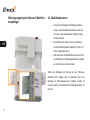
Einbauanleitung
Installation guide
Sehr geehrte Kundin, sehr geehrter Kunde,
wir bedanken uns für den Kauf der Standheizungs-Fernbedienung dfreeeze®. Das System
ermöglicht Ihnen die komfortable Steuerung Ihrer Standheizung über das Internet. Zur
DE
Steuerung stehen Ihnen Apps für die Betriebssysteme Android und iOS zur Verfügung.
Außerdem können Sie Ihre Standheizung über das Internet von jedem Smartphone, Tablet,
PC oder Mac steuern.
Diese Einbauanleitung ergänzt die Bedienungsanleitung und enthält alle Informationen, die
Sie zum Einbau benötigen. Bitte bewahren Sie diese Anleitung sorgfältig (zum Beispiel im
Bordbuch Ihres Fahrzeuges) auf.
2
Inhalt
1 Gefahren- und Warnhinweise.................................................................................................................................. 4
2Vorbemerkungen....................................................................................................................................................... 4
3Lieferumfang............................................................................................................................................................. 5
4 Einbau und Montage................................................................................................................................................. 5
4.1Mobilfunkempfänger................................................................................................................................................................. 5
DE
4.2Mobilfunkantenne..................................................................................................................................................................... 6
4.3Temperaturfühler...................................................................................................................................................................... 7
5Anschluss.................................................................................................................................................................. 8
5.1Adapterkabel............................................................................................................................................................................ 8
5.2
Verbaukonfigurationen........................................................................................................................................................... 11
6Bedienung................................................................................................................................................................ 20
6.1Testphase............................................................................................................................................................................... 20
7 Technische Merkmale............................................................................................................................................. 21
7.1Empfänger.............................................................................................................................................................................. 21
7.2Antenne.................................................................................................................................................................................. 22
3
DE
1 Gefahren- und Warnhinweise
2 Vorbemerkungen
Der Einbau des dfreeeze® Empfängers darf ausschließlich
Der dfreeeze® Empfänger ist vollständig betriebsbereit
durch ausgebildetes Fachpersonal erfolgen. Versuchen
und eignet sich zur Steuerung zahlreicher Standhei-
Sie nicht, den dfreeeze® Empfänger oder dessen Zubehör
zungen.
zu reparieren.
Die hier vorliegende Einbauanleitung beschreibt den
Beachten Sie bitte immer diese Einbauanleitung und
Einbau des dfreeeze® Systems mit verschiedenen Stand-
insbesondere die enthaltenen Gefahren- und Warnhin-
heizungen.
weise. Jede Haftung, die auf einen Eingriff durch
Im dfreeeze® Empfänger werden hauptsächlich für die
ungeschultes Personal zurückzuführen ist, lehnt digades
Automobilindustrie zertifizierte Komponenten verwendet.
ab.
Das Gerät ist ausschließlich zur Steuerung von Standheizungen vorgesehen und darf nicht für andere Zwecke
verwendet werden.
4
3 Lieferumfang
●●
Der Einbau erfolgt bevorzugt senkrecht mit
den Steckverbindern nach unten, um das
Das dfreeeze® System besteht aus:
●●
●●
●●
Mobilfunkempfänger
Eindringen von Kondenswasser zu vermeiden.
●●
im Lieferumfang befindlichen Kabelbinder und
Adapterkabelbaum inklusive zusätzlicher
Klebesockeln erfolgen. (Beispiel siehe nächste
Stecker
●●
●●
Die Fixierung des Empfängers kann mit den
Scheibenklebeantenne
Einbau- und Bedienungsanleitung
Montagematerial (Klebesockel, Kabelbinder)
Seite).
●●
DE
Die Einbauposition des Empfängers sollte in
der nachfolgenden Skizze markiert werden.
4 Einbau und Montage
4.1 Mobilfunkempfänger
●●
Der Einbau des dfreeeze® Mobilfunkemp-
●●
Bei vorhandenem T91/T100 Funkempfänger
fängers muss im Fahrzeuginnenraum erfolgen.
muss der Einbau in dessen Nähe erfolgen.
Eine Übersicht zu den üblichen Verbauorten
des T91/T100 Funkempfängers finden Sie unter
www.dfreeeze.de/support
5
Befestigungsbeispiel dfreeeze® Mobilfunkempfänger
4.2 Mobilfunkantenne
●●
Um einen bestmöglichen Empfang sicherzustellen, sollte die Mobilfunkantenne innen auf
der Front- oder Heckscheibe möglichst mittig
montiert werden.
DE
●●
Der Empfang ist optimal, wenn ein Abstand
zu Karosserieblechteilen zwischen 15mm und
25mm eingehalten wird.
●●
Alternativ kann die Mobilfunkantenne bei leicht
verschlechterter Empfangsqualität auch seitlich
an der Scheibe montiert werden.
Sollte eine Montage der Antenne an den Fahrzeugscheiben nicht möglich sein, ist alternativ auch eine
Montage im Fahrzeuginnenraum möglich. Hierbei ist
mit einem leicht verschlechterten Empfangsverhalten zu
rechnen.
6
Beim Aufkleben der Mobilfunkantenne an der Scheibe
4.3 Temperaturfühler
sind die folgenden Punkte zu beachten:
Der Temperaturfühler muss im Fahrzeuginnenraum
●●
●●
Die Windschutzscheibe muss fett- und staubfrei
verbaut werden. Suchen Sie je nach Fahrzeug einen
sein.
geeigneten Einbauort.
Die Schutzfolie muss von der Antenne
abgezogen werden und die Antenne an der
Für eine möglichst genaue Ermittlung der Innenraumtem-
gereinigten Stelle der Scheibe aufgeklebt
peratur sollte der Temperatursensor:
DE
werden.
●●
Bitte achten Sie auf ein knickfreies Verlegen
●●
keiner direkten Sonneneinstrahlung ausgesetzt
●●
nicht in der Nähe von Karrosserieteilen platziert
sein
des Kabels.
●●
Das Kabel der Mobilfunkantenne ist ein
sein, die einer direkten Sonneinstrahlung
Hochfrequenzkabel, das nicht gekürzt werden
ausgesetzt sind
darf.
●●
Wenn das Kabel zu lang ist, sollte es ringförmig
aufgewickelt werden. Der Ringdurchmesser
●●
nicht direkt vor einem Lüftungsauslass platziert
werden.
sollte möglichst groß und auf keinen Fall kleiner
als 60mm sein.
Bitte beachten Sie, dass am W-Bus nur EIN
Temperatursensor angeschlossen sein darf. Dies
betrifft die Verbaukonfigurationen 1, 2 und 3,
sofern im Fahrzeug bereits ein Webasto-Temperatursensor vorhanden ist.
7
5 Anschluss
5.1 Adapterkabel
Der dfreeeze® Mobilfunkempfänger wird mit Ihrer Standheizung verbunden. Dazu liegen ein individiuell konfigurierbarer Kabeladapter sowie zusätzlich zwei Steckergehäuse bei. Mit den bereits angebrachten schwarzen
DE
Steckergehäusen ist der Kabeladapter zur Verwendung
mit nachgerüsteten Webasto-Standheizungen sowie vieler ab Werk verbauter Standheizungen geeignet.
Die getrennt beiliegenden blauen Steckergehäuse sind
mit ab Werk verbauten Standheizungen oder als original
Zubehör unter anderem von Volkswagen, Skoda und
Seat kompatibel.
Für den Anschluss an weitere Standheizungen müssen
Pinbelegung Adapterkabel
Pin
X1
X2
1
2
3
X3
X4
12V
W-Bus*
je nach Verbaukonfiguration**
4
je nach Verbaukonfiguration**
5
frei
GND
6
GND
* Die W-Bus-Leitung ist je nach Verbaukonfiguration nicht
immer durchgängig verbunden.
** Pin 3 und Pin 4 sind je nach Konfiguration entweder frei
oder mit Schaltausgang und -eingang belegt.
unter Umständen die Leitungen direkt verdrahtet werden.
Weitere Informationen zum Einbau und Anschluss
des dfreeeze® Systems mit fahrzeugspezfischen
Informationen finden Sie unter www.dfreeeze.de/
support.
8
Lesen Sie die detaillierte Beschreibung der
Verbaukonfigurationen auf den folgenden Seiten
für nähere Informationen.
Adapterkabel dfreeeze®
X3
dfreeeze® Empfänger
X4
Temperatursensor
Tyco 1-1718346-2
Tyco 1-1241370-3
DE
X1
X2
zusätzlicher Funkempfänger
Standheizung
schwarz:
Tyco 1-1241370-3
schwarz:
Tyco 170384-1
blau:
VW 6Q0 972 706
blau:
VW 6Q0 972 716
9
Vorbereiten des Adapterkabels
Um das Adapterkabel möglichst universell einsetzbar
zu gestalten, sind im Auslieferungszustand nicht alle
Leitungen kontaktiert. Sie können daher Ihr Kabel je nach
Verbaukonfiguration entsprechend anpassen.
●●
Achten Sie darauf, dass die Führungsfeder am
Steckkontakt in die zugehörige Führungsnut
am Steckergehäuse eingeführt wird.
●●
Achten Sie darauf, dass der Steckkontakt
vollständig im Gehäuse eingerastet ist.
●●
Versuchen Sie nicht, den Steckkontakt mit
Gewalt in das Steckergehäuse einzuschieben.
DE
Stecken von Kontaktstiften in das Gehäuse
Betrifft: Verbaukonfiguration 1-2; 4-71
Verbindung der W-Bus-Leitung (gelb)
Betrifft: Verbaukonfiguration 1-31
Beachten Sie beim Steckenn der Kontaktstifte die
folgenden allgemeinen Hinweise:
Zum Verbinden der gelben W-Bus-Leitung zwischen
Stecker X2 und X3:
●●
Entfernen Sie die Transportsicherung und
ziehen Sie die Isolierschläuche von den
Kontakten ab.
●●
Achten Sie auf die korrekte Pinbelegung; die
Kammern sind am Steckergehäuse nummeriert
●●
Ziehen Sie die beiden gelben Leitungsenden
aus der mittleren Bündelung heraus
●●
●●
Ziehen Sie die Isolierung der Leitung ab
Stecken Sie zuerst das eine, danach das
Die jeweilige Pinbelegung finden Sie in der
andere Leitungsende in den beiliegenden
Detailbeschreibung auf den folgenden Seiten.
Stoßverbinder und verpressen Sie beide Seiten
nacheinander mit einer geeigneten Zange.
10
1 Zur Erläuterung der Verbaukonfigurationen siehe
Seiten 11 bis 18
Anbringen der blauen Steckergehäuse (VW)
Betrifft: Verbaukonfiguration 4-51
5.2 Verbaukonfigurationen
Bitte beachten Sie, dass der dfreeeze® Empfänger je
Für die Verwendung des dfreeeze® mit ab Werk verbauten
nach Fahrzeug für eine korrekte Funktion des dfreeeze®
oder als original Zubehör nachgerüsteten Standhei-
Systems entsprechend der Verbaukonfiguration initiali-
zungen unter anderem von Volkswagen, Skoda und Seat
siert werden muss.
ist es erforderlich die Steckergehäuse X1 und X2 gegen
die beiliegenden blauen Gehäuse zu ersetzen.
Eine Schritt-für-Schritt-Anleitung zum Umbau des
Kabeladapters zur Verwendung mit den blauen
VW-Steckergehäusen finden Sie unter www.
dfreeeze.de/support
Sichern der nicht benötigten Leitungsenden
Betrifft: alle Verbaukonfigurationen
●●
DE
Verbaukonfiguration
Seite
1 - Stand Alone mit Taster
12
2 - Stand Alone mit Vorwahluhr
12
3 - Telestart über W-Bus
14
4 - Telestart VW MQB (LIN)
16
5 - Telestart VW PQ (W-Bus)
16
6 - Empfänger analog (Uhr)
18
7 - Empfänger analog (Taster)
18
Isolieren Sie nach dem Einbau und Test des
dfreeeze® Systems nicht benötigte Leitungsenden beispielsweise mit Isolierband.
Bitte informieren Sie Ihren Kunden über die
korrekte Verbaukonfiguration.
11
Verbaukonfigurationen 1 & 2
Die Verbaukonfigurationen 1 & 2 beschreiben den
Vorbereitung Adapterkabel
●●
Anschluss des dfreeeze® Empfängers an eine Webasto
enden mit dem mitgelieferten Stoßverbinder
Standheizung mit W-Bus als alleinige Fernbedienungsmöglichkeit sowie die Kombination mit Taster bzw. Uhr.
wie im Kabelplan rechts dargestellt (Pin 2).
●●
Kontaktieren Sie den Stecker X3 wie im
Kabelplan rechts dargestellt.
DE
Verbaukonfiguration 1: Stand Alone mit Taster
Beachten Sie bei der Vorbereitung des Kabels
die Hinweise auf Seite 10.
Beliebige Standheizung, die wie nachfolgend beschrieben konfiguriert ist.
Schaltausgang - Pin 3*
12V Dauersignal
(z.B. LED Taster)
Schalteingang - Pin 4*
12V Schaltimpuls
Verbaukonfiguration 2: Stand Alone mit Uhr
Beliebige Standheizung, die wie nachfolgend beschrieben konfiguriert ist.
Schaltausgang - Pin 3*
12V Dauersignal
Schalteingang - Pin 4*
12V Dauersignal
*Die Angaben beziehen sich auf die Signale am
12
Verbinden Sie die beiden gelben Leitungs-
dfreeeze® Empfänger (Stecker X3).
Anschluss dfreeeze® Empfänger
●●
Verbinden Sie die Steckverbinder mit den
jeweiligen Geräten wie in der Systemdarstellung gezeigt.
Taster/Uhr
Webasto
frei
Kabelbaum Webasto
Adapterkabel
9021440B
dfreeeze®
Temperatursensor
Webasto
dfreeeze® Empfänger
Standheizung
Systemdarstellung Standheizung / dfreeeze®
Temperatursensor
dfreeeze®
DE
Adapterkabel dfreeeze®
X1
X2
X3
X4
1
2
3
4
5
6
1
2
3
4
5
6
1
2
3
4
5
6
1
2
3
frei
Kabelbaum
Webasto
dfreeeze®
Empfänger
Temperatursensor
dfreeeze®
13
Verbaukonfiguration 3
Vorbereitung Adapterkabel
Die Verbaukonfiguration 3 beschreibt den Anschluss des
●●
Standheizung
mit
bereits
vorhandenem
wie im Kabelplan rechts dargestellt.
Funkemp-
fänger T91/T100, der über W-Bus an die Standheizung
●●
angeschlossen ist. Zudem ist die Konfiguration auch
DE
Verbinden Sie die beiden gelben Leitungsenden mit dem mitgelieferten Stoßverbinder
dfreeeze® Empfängers an eine nachgerüstete Webasto
Kontaktieren Sie den Stecker X1 wie im
Kabelplan rechts dargestellt.
möglich bei ab Werk verbauten Standheizungen der
Beachten Sie bei der Vorbereitung des Kabels
die Hinweise auf Seite 10.
Marken Ford, Peugeot, Citroen und Landrover mit
vorhandenem T91/T100 Funkempfänger.
Anschluss dfreeeze® Empfänger
Verbaukonfiguration 3 Telestart über W-Bus
Nachgerüstete
Webasto-Standheizungen
mit
vorhandenem Funkempfänger T91/T100 und W-Bus
●●
Verbinden Sie die Steckverbinder mit den
jeweiligen Geräten wie in der Systemdarstellung gezeigt.
Pin 2*
W-Bus
*Die Angaben beziehen sich auf die Signale am
dfreeeze® Empfänger (Stecker X3).
14
Taster/Uhr
Webasto
Telestart
T91/T100
Kabelbaum Webasto
Adapterkabel
9021440B
dfreeeze®
Temperatursensor
Webasto
dfreeeze® Empfänger
Standheizung
Systemdarstellung Standheizung / dfreeeze®
Temperatursensor
dfreeeze®
DE
Adapterkabel dfreeeze®
X1
X2
X3
X4
1
2
3
4
5
6
1
2
3
4
5
6
1
2
3
4
5
6
1
2
3
Telestart
T91/T100
Kabelbaum
Webasto
dfreeeze®
Empfänger
Temperatursensor
dfreeeze®
15
Verbaukonfigurationen 4 & 5
*Die Angaben beziehen sich auf die Signale am
dfreeeze® Empfänger (Stecker X3).
Die Verbaukonfigurationen 4 & 5 beschreiben den
Anschluss des dfreeeze® Empfängers an eine Original
Ist kein Rückmeldesignal an Pin 4 an Stecker
X3 vorhanden, kann die einwandfreie Funktion
des dfreeeze® nicht gewährleistet werden.
VW Standheizung (ab Werk verbaut oder als original
Zubehör nachgerüstet).
DE
Verbaukonfiguration 4: Telestart VW MQB LIN
Fahrzeuge basierend auf MQB (z.B. VW Golf VII,
Vorbereitung Adapterkabel
●
Zum Anschluss einer orginal VW Standheizung
müssen die Stecker X1 und X2 gegen die
Skoda Oktavia III)
Schaltausgang - Pin 3*
12V Dauersignal
Schalteingang - Pin 4*
12V Dauersignal
blauen VW Stecker ausgetauscht werden.
●
Kontaktieren Sie die Stecker X1 und X3 wie im
Kabelplan rechts dargestellt.
(zur Rückmeldung)
Beachten Sie bei der Vorbereitung des Kabels
die Hinweise auf Seite 10.
Verbaukonfiguration 5: Telestart VW PQ W-Bus
Fahrzeuge basierend auf der PQ-Plattform (z.B. VW
Golf VI, VW Touran)
16
Anschluss dfreeeze® Empfänger
●
Schaltausgang - Pin 3*
12V Schaltimpuls
Schalteingang - Pin 4*
12V Dauersignal
jeweiligen Geräten wie in der Systemdar-
(zur Rückmeldung)
stellung rechts gezeigt.
Verbinden Sie die Steckverbinder mit den
Telestart
T91/T100 VW
dfreeeze® Empfänger
Standheizung VW
Systemdarstellung Standheizung / dfreeeze®
Adapterkabel
Kabelbaum Fahrzeug
dfreeeze®
Temperatursensor
dfreeeze®
DE
Adapterkabel dfreeeze®
X1
X2
X3
X4
1
2
3
4
5
6
1
2
3
4
5
6
1
2
3
4
5
6
1
2
3
Telestart
T91/T100 VW
Kabelbaum
Fahrzeug
dfreeeze®
Empfänger
Temperatursensor
dfreeeze®
17
Verbaukonfigurationen 6 & 7
*Die Angaben beziehen sich auf die Signale am dfreeeze®
Empfänger (Stecker X3).
Die Verbaukonfigurationen 6 & 7 beschreiben den
Anschluss des dfreeeze® Empfängers an eine beliebige
Ist kein Rückmeldesignal an Pin 4 vorhanden,
kann die einwandfreie Funktion des dfreeeze®
nicht gewährleistet werden.
Standheizung mit Schaltaus und -eingang, die wie
nachfolgendbeschriebenkonfiguriertsind.
DE
Verbaukonfiguration 6: Empfänger analog Uhr
Beliebige Standheizung, die wie nachfolgend beschriebenkonfiguriertist.
Vorbereitung Adapterkabel
●
Schaltausgang - Pin 3*
12V Dauersignal
Schalteingang - Pin 4*
12V Dauersignal
Kabelplan rechts dargestellt.
Beachten Sie bei der Vorbereitung des Kabels die
Hinweise auf Seite 10.
(zur Rückmeldung)
Verbaukonfiguration 7: Empfänger analog Tast-
Anschluss dfreeeze® Empfänger
er
Beliebige Standheizung, die wie nachfolgend beschriebenkonfiguriertist.
●
Verbinden Sie die Steckverbinder mit den
jeweiligen Geräten wie in der Systemdar-
Schaltausgang - Pin 3*
12V Schaltimpuls
Schalteingang - Pin 4*
12V Dauersignal
(zur Rückmeldung)
18
Kontaktieren Sie den Stecker X3 wie im
stellung rechts gezeigt.
dfreeeze® Empfänger
Standheizung
●●
Systemdarstellung
Standheizung / dfreeeze®
Adapterkabel
Kabelbaum Standheizung
dfreeeze®
Temperatursensor
dfreeeze®
DE
Adapterkabel dfreeeze®
X1
X2
X3
X4
1
2
3
4
5
6
1
2
3
4
5
6
1
2
3
4
5
6
1
2
3
frei
Kabelbaum
Standheizung
dfreeeze®
Empfänger
Temperatursensor
dfreeeze®
19
DE
6 Bedienung
6.1 Testphase
Zur Benutzung des dfreeeze® Systems muss entweder
Für einen Funktionstest nach erfolgtem Einbau steht
auf einem geeigneten Smartphone (Android oder iOS)
Ihnen als Werkstatt einmalig eine kostenlose 7-tägige
eine App installiert oder über jeden gängigen Internetbro-
Testphase zur Verfügung.
wser (Mozilla Firefox, Google Chrome, Internet Explorer
Geben Sie dazu bei der Initialisierung des Gerätes den
ab Version 10, Safari, Opera) unter app.dfreeeze.de auf-
Verification Key „123456“ ein.
gerufen werden:
(siehe auch Kap. 5 und Bedienungsanleitung Kap. 3.3)
Machen Sie es sich einfach und scannen Sie den
QR-Code – Sie werden automatisch zur richtigen
App weitergeleitet.
Die Benutzung der App
ist in der Anwendung im
Bereich „Info“ sowie in
der
Bedienungsanleitung
beschrieben.
20
7 Technische Merkmale
7.1 Empfänger
Übertragungsbänder:
GSM (850 MHz), EGSM (900 MHz), DCS (1800 MHz), PCS (1900
MHz)
Busanbindung:
W-Bus
Betriebsspannung:
12 V DC (9 bis 16 V DC)
Ruhestromaufnahme:
< 5 mA (Standby Mode)
Max. Stromaufnahme (GSM-Burst)
:
ca. 800 mA (12 V DC)
Max. zulässige Absicherung
:
5A
Arbeitstemperatur:
-40°C bis +85°C
Anschlüsse:
Antenneneinbaustecker: FAKRA, Code D, Farbe Bordeaux, 50 Ω
Abmessungen B x H x T [mm]
65 x 98 x 24
DE
Systemeinbaustecker: 6-polig, Tyco, 1-1241370-3
:
Gewicht:
ca. 70 g
Schutzart:
IP43
21
Pinbelegung Empfänger
6 ... 1
1 – 12V
4 – Schalteingang
2 – W-Bus
5 – frei
3 – Schaltausgang
6 – Masse (GND)
DE
7.2 Antenne
Übertragungsbänder
:
GSM (850 MHz), EGSM (900 MHz), DCS (1800 MHz), PCS (1900
Impedanz
:
50Ω
Gain
:
2,14 dBi
Arbeitstemperatur
:
-40°C bis +85°C
Kabel
:
Typ: RG174, Länge 2,5 m
Kupplung
:
FAKRA, Code D, Farbe Bordeaux
Abmessungen B x H x T [mm]
:
119,0 x 14,8 x 6,7
Gewicht
:
13 g
MHz)
22
Für Ihre Notizen
DE
23
Dear customer,
Thank you for purchasing the dfreeeze® parking heater remote control. With this system, you
can easily control your parking heater via the Internet with the aid of apps for android and iOS
operating systems. You can also control your parking heater via the internet using any smart
phone, tablet, PC or Mac.
EN
This installation guide supplements the user manual and contains everything you need to
know to install the system. Please keep this manual in a safe place (for example, in your
vehicle logbook).
24
Content
1 Hazard information and warnings......................................................................................................................... 26
2 Preliminary remarks................................................................................................................................................ 26
3 Product contents..................................................................................................................................................... 27
4 Installation and mounting...................................................................................................................................... 27
4.1
Mobile receiver....................................................................................................................................................................... 27
4.2
Mobile antenna....................................................................................................................................................................... 28
4.3
Temperature sensor............................................................................................................................................................... 29
5Connecting.............................................................................................................................................................. 30
5.1
Adapter cable......................................................................................................................................................................... 30
5.2
Installation configurations....................................................................................................................................................... 33
EN
6Operating................................................................................................................................................................. 42
6.1
Test phase.............................................................................................................................................................................. 42
7 Technical features................................................................................................................................................... 43
7.1Receiver................................................................................................................................................................................. 43
7.2Antenna.................................................................................................................................................................................. 44
25
EN
1 Hazard information and warnings
2 Preliminary remarks
The dfreeeze® receiver may only be installed by a
The dfreeeze® receiver is fully operational and can be
qualified professional. Please do not attempt to repair the
used to control a large number of parking heaters.
dfreeeze® receiver or any of the accessories yourself.
This installation guide describes the installation of the
Please always refer to this user manual and in particular
receiver in Volkswagen vehicles with parking heaters
to the hazard information and warnings contained herein.
installed ex works or retrofitted as original VW acces-
Digades shall not assume any liability for consequences
sories.
arising as a result of action by unqualified individuals.
The dfreeeze® receiver primarily comprises components
The device is intended solely as a means of controlling
parking heaters and may not be used for other purposes.
26
certified in line with automotive standards.
3 Product contents
●●
The dfreeeze® mobile receiver should
preferably be installed facing in a downward
The dfreeeze® system comprises:
●●
●●
●●
●●
●●
direction perpendicular to the plug connections
Mobile receiver
in order to prevent condensation entering the
Windscreen antenna
adapter cable incl. connectors
device.
●●
The receiver may be secured in place using
User manual and installation guide
the cable strap and adhesive mount included
Mounting material (adhesive mount, cable
with the device. (An example is shown on the
strap)
next page)
●●
4 Installation and mounting
The installation position should be indicated on
EN
the following drawing.
4.1 Mobile receiver
●●
The installation of the dfreeze® mobile radio
●●
In the event of existing T91/T100 radio
receiver must take place inside of the vehicle
receivers, this must take place in its vicinity
You will find an overview of the standard
installation locations for the T91 receiver at
www.dfreeeze.de/support
27
4.2 Mobile antenna
●●
In order to ensure the best possible reception,
the mobile antenna should be mounted as
close as possible to the centre of the inside of
the front or back windscreen.
●●
The optimum reception will be obtained where
a distance of between 15 mm and 25 mm to all
parts of the bodywork is maintained.
EN
●●
Alternatively, the mobile antenna may also
be mounted to the side of the windscreen,
although this will result in a slight reduction in
reception quality.
Should it not be possible to mount the antenna on the
vehicle windscreen, it may alternatively be mounted in the
interior of the vehicle, however this will probably result in
a slight reduction in reception quality.
28
Please have regard to the following points when affixing
4.3 Temperature sensor
the mobile antenna to the windscreen:
The temperature sensor must be installed in the interior
●●
●●
●●
The windscreen must be free of any grease or
of the vehicle. You should select an appropriate location,
dust.
depending on the type of vehicle concerned.
The protective film must be removed from the
antenna and the antenna affixed to a clean
In order to ensure the greatest possible precision in
area of the windscreen.
measuring the temperature inside the vehicle, the temper-
Please ensure that the cable is laid flat without
ature sensor should not be:
EN
any kinks.
●●
The cable for the mobile antenna is a high-frequency cable and may not be shortened.
●●
●●
●●
Installed in close proximity to any parts of the
bodywork that is exposed to direct sunlight.
If the cable is too long, it should be wound up
into coils, keeping the diameter of the coils as
Exposed to direct sunlight
●●
placed directly in front of an air outlet.
large as possible and no smaller than 60 mm.
Please note that only ONE temperature sensor
may be connected to the W-bus. This concerns
the installation configurations 1, 2 and 3, provided
a Webasto temperature sensor is already present
in the vehicle.
29
5 Connecting
5.1 Adapter cable
The dfreeeze® mobile radio receiver is connected with
your parking heating. In addition, there is an individually configurable cable adapter and additional two
plug housings. With the black plug housings already
attached, the cable adapter is suitable for use with retro-
EN
Pin assignment of the adapter cable
Pin
X1
X2
X3
1
2
W-Bus*
fitted Webasto parking heaters as well as many parking
3
heaters installed ex works.
depending on the installation
configuration**
4
depending on the installation
configuration**
The separate enclosed blue plug housings are compatible
X4
12V
with parking heaters installed ex works or as original
5
free
accessories, among others Volkswagen, Skoda and Seat.
6
GND
GND
For connection to other parking heaters, the lines must be
wired directly in certain circumstances.
* The W-bus cable is not always continuously connected
depending on the installation configuration.
** Depending on the configuration, pin 3 and pin 4 are
More information about the installation and
connection of the dfreeeze® system with partly
vehicle-specific information can be found at www.
dfreeeze.de/support.
30
either free or occupied with switching output or input.
Read the detailed description of the installation
configuration on the following pages for more
information.
Adapter cable dfreeeze®
X3
dfreeeze® receiver
X4
Temperature sensor
Tyco 1-1718346-2
Tyco 1-1241370-3
EN
X1
X2
additional radio
receiver
Parking heater
black:
Tyco 1-1241370-3
blue:
VW 6Q0 972 706
black:
Tyco 170384-1
blue:
VW 6Q0 972 716
31
●●
Preparation of the adapter cable
Note the tongue on the plug contact as well
as the associated guide groove on the plug
To make the adapter cable as universally applicable as
housing.
●●
possible, not all lines are connected in the delivery state.
Depending on the installation configuration, you must
Ensure that the plug contact is completely
seated in the housing.
●●
therefore prepare your cable accordingly.
Do not attempt to insert the plug contact into
the plug housing with force.
Insertion of contact pins into the housing
Concerns: Installation configuration 1-2; 4-71
EN
When plugging in the contact pins, note the following
general information:
Connection with the W-bus cable (yellow)
Concerns: Installation configuration 1-31
To connect the yellow W-bus cable between plug X2 and
X3:
●●
Remove the transport lock and pull the
insulating sleeve from the contacts.
●●
Note the correct pin assignment; the chambers
are numbered on the plug housing
You can find the respective pin assignment in
the detailed description on the following pages-
●●
Pull both yellow cable ends out of the middle
bundling
●●
●●
Pull the insulation off of the cable
First insert one cable end and then the other
end of the cable into the accompanying butt
connector and crimp both sides successively
with suitable pliers.
32
Attaching the blue plug housing (VW)
Concerns: Installation configuration 4-51
5.2 Installation configurations
Please note that, depending on the vehicle, the receiver
To use the dfreeeze® with parking heaters installed ex
must be initialised according to the installation config-
works or parking heaters retrofitted as original acces-
uration in order to ensure a correct function of the
sories, such as Volkswagen, Skoda and Seat, it is
dfreeeze® system. Please also refer to the enclosed
necessary to replace the plug housing X1 and X2 with the
Instruction Manual in this regard.
enclosed blue housing.
A step-by-step instruction for retrofitting the cable
adapter for use with the blue VW plug housing can
be found at www.dfreeeze.de/support
Secure the unused cable ends
Concerns: all installation configurations 1
●●
After the installation and test of the dfreeeze®
system, insulate the unused cable ends, for
Installation configuration
Page
1 - Stand Alone with button
34
2 - Stand Alone with pre-selection clock
34
3 - Telestart via W-bus
36
4 - Telestart VW MQB (LIN)
38
5 - Telestart VW PQ (W-bus)
38
6 - Receiver analogue (clock)
40
7 - Receiver analogue (button)
40
EN
example with electrical tape.
Please
notify
your
customer
correct installation configuration.
of
the
33
Installation configuration 1 & 2
*The information refers to the signals on the dfreeeze®
receiver (plug X3).
The installation configurations 1 & 2 describe the
connection of the dfreeeze® receiver to a Webasto parking
heater with W-bus as the only remote control possibility
Preparation of the adapter cable
●●
as well as the combination with buttons or a clock.
Connect the two yellow cable ends with the
supplied butt connectors as shown in the cable
diagram to the right (pin 2).
Installation config 1: Stand Alone with button
EN
●●
Any parking heater that is configured as described
Connect the plug X3 as shown in the cable
diagram on the right.
below.
Switching output - Pin 3*
Note the information on page 32 when
preparing the cable.
12V continuous signal
(e.g. LED button)
Switching input - Pin 4*
12V switching impulse
Installation configuration 2: Stand Alone with
clock
Any parking heater that is configured as described
below.
34
Switching output - Pin 3*
12V continuous signal
Switching input - Pin 4*
12V continuous signal
Connecting the dfreeeze® receiver
●●
Connect the plug connector with the respective
devices as shown in the system diagram to the
right.
Button / clock
Webasto
Webasto wiring
harness
Adapter cable
9021440B
dfreeeze®
Temperature sensor
Webasto
dfreeeze® receiver
Parking heater
System representation of the parking heater / dfreeeze®
Temperature sensor
dfreeeze®
EN
Adapter cable dfreeeze®
X1
X2
X3
X4
1
2
3
4
5
6
1
2
3
4
5
6
1
2
3
4
5
6
1
2
3
free
Wiring harness
Webasto
dfreeeze®
Recipient
Temperature
sensor
dfreeeze®
35
Installation configuration 3
The installation configuration 3 describes the connection
Preparation of the adapter cable
●●
supplied butt connectors as shown in the cable
of the dfreeeze® receiver to a retrofitted Webasto parking
heater with an already existing radio receiver T91/T100,
diagram to the right.
●●
which is connected to the parking heater via W-bus. In
Connect the plug X1 as shown in the cable
diagram on the right..
addition, the configuration is also possible for ex works-in-
Note the information on page 32 when
preparing the cable.
stalled parking heaters from the brands Ford, Peugeot,
Citroen and Landrover with the existing T91/T100 radio
EN
Connect the two yellow cable ends with the
receiver.
Connecting the dfreeeze® receiver
Installation configuration 3 Telestart via W-bus
Connect the plug connector with the respective
devices as shown in the system diagram to the
receiver T91/T100 and W-bus.
right.
Pin 2*
W-Bus
*The information refers to the signals on the dfreeeze®
receiver (plug X3).
36
●●
Retrofitted Webasto parking heaters with existing radio
Button / clock
Webasto
Telestart
T91/T100
Webasto wiring
harness
Adapter cable
9021440B
dfreeeze®
Temperature sensor
Webasto
dfreeeze® receiver
Parking heater
System representation of the parking heater / dfreeeze®
Temperature sensor
dfreeeze®
EN
Adapter cable dfreeeze®
X1
X2
X3
X4
1
2
3
4
5
6
1
2
3
4
5
6
1
2
3
4
5
6
1
2
3
Telestart
T91/T100
Wiring harness
Webasto
dfreeeze®
Receiver
Temperature
sensor
dfreeeze®
37
Installation configuration 4 & 5
*The information refers to the signals on the dfreeeze®
receiver (plug X3).
The installation configurations 4 & 5 describe the
connection of the dfreeeze® receiver to an original VW
If no feedback signal to pin 4 on plug X3 is
present, the proper function of the dfreeeze®
cannot be guaranteed.
parking heater (installed ex works or retrofitted as an
original accessory).
Installation configuration 4: Telestart VW MQB
Vehicles
EN
based
on
MQB
(e.g.
VW
Golf
VII,
Preparation of the adapter cable
●
To connect an original VW parking heater, the
plugs X1 and X2 must be replaced with the
Skoda Oktavia III)
Switching output - Pin 3*
12V continuous signal
Switching input - Pin 4*
12V continuous signal
blue VW plugs.
●
Connect the plugs X1 and X3 as shown in the
cable diagram on the right.
(for response)
Note the information on page 32 when
preparing the cable.
Installation configuration 5: Telestart VW PQ
Vehicles based on the PQ-platform (e.g. VW Golf VI,
VW Touran)
38
Connecting the dfreeeze® receiver
●
Switching output - Pin 3*
12V switching impulse
Switching input - Pin 4*
12V continuous signal
devices as shown in the system diagram to the
(for response)
right.
Connect the plug connector with the respective
Telestart
T91/T100 VW
dfreeeze® receiver
VW parking heater
System representation of the parking heater / dfreeeze®
Adapter cable
Vehicle wiring harness
dfreeeze®
Temperature sensor
dfreeeze®
EN
Adapter cable dfreeeze®
X1
X2
X3
X4
1
2
3
4
5
6
1
2
3
4
5
6
1
2
3
4
5
6
1
2
3
Telestart
T91/T100 VW
Wiring harness
Vehicle
dfreeeze®
Receiver
Temperature
sensor
dfreeeze®
39
Installation configuration 6 & 7
*The information refers to the signals on the dfreeeze®
receiver (plug X3).
The installation configurations 6 & 7 describe the
connection of the dfreeeze® receiver to any parking heater
If no feedback signal to pin 4 is present, the
proper function of the dfreeeze® cannot be
guaranteed.
withswitchingoutputandinput,whichareconfiguredas
described below.
Inst. configuration 6: Receiver analogue clock
EN
Any parking heater that is configured as described
below.
Preparation of the adapter cable
●
diagram on the right.
Switching output - Pin 3*
12V continuous signal
Switching input - Pin 4*
12V continuous signal
Note the information
preparing the cable.
(for response)
Inst. configuration 7: Receiver analogue button
Any parking heater that is configured as described
on
page
32
when
Connecting the dfreeeze® receiver
●
Connect the plug connector with the respective
devices as shown in the system diagram to the
below.
Switching output - Pin 3*
12V switching impulse
Switching input - Pin 4*
12V continuous signal
(for response)
40
Connect the plug X3 as shown in the cable
right.
dfreeeze® receiver
Parking heater
System representation of the parking heater / dfreeeze®
Adapter cable
Parking heater wiring harness
dfreeeze®
Temperature sensor
dfreeeze®
EN
Adapter cable dfreeeze®
X1
X2
X3
X4
1
2
3
4
5
6
1
2
3
4
5
6
1
2
3
4
5
6
1
2
3
free
Wiring harness
Parking heater
dfreeeze®
Receiver
Temperature
sensor
dfreeeze®
41
EN
6 Operating
6.1 Test phase
In order to enable the use of the dfreeeze® system, an
As a car service station, you will have the benefit of a free
app must either be installed on a suitable smart phone
7-day test phase for functional testing purposes following
(Android oder iOS) or opened using an established
the successful installation of the receiver.
internet browser (Mozilla Firefox, Google Chrome,
In order to take advantage of this feature, please enter the
Version 10 of Internet Explorer and above, Safari, Opera)
verification key “123456” upon initialising of the device.
browsing to the address app.dfreeeze.de.
(see also Point 5, and Point 3.3 of the user manual)
Simply scan the QR code – and you will be
automatically be directed to the correct app.
The “Info” section and the
user manual explain how to
use the app.
42
7 Technical features
7.1 Receiver
Transmission bands
:
GSM (850 MHz), EGSM (900 MHz), DCS (1800 MHz), PCS (1900
MHz)
Bus connection
:
W-Bus
Operating voltage
:
12 V DC (9 to 16 V DC)
Standby current
:
< 5 mA (standby mode)
Max. current consumption (GSM burst)
:
Approx. 800 mA (12 V DC)
Max. permissible fuse protection
:
5A
Working temperature
:
Connectors:
EN
-40°C to +85°C
Antenna plug connector: FAKRA, Code D, burgundy-coloured, 50 Ω
System plug connector: 6-pin, Tyco, 1-1241370-3
Dimensions B x H x T [mm]
:
65 x 98 x 24
Weight:
Approx. 70 g
Protection rating
IP43
:
43
Pin assignment for receiver
6 ... 1
EN
1 – 12V
4 – Switch input
2 – W-Bus
5 – Open
3 – Switch output
6 – Ground (GND)
7.2 Antenna
Transmission bands
:
GSM (850 MHz), EGSM (900 MHz), DCS (1800 MHz), PCS (1900
Impedance
:
50Ω
Gain
:
2.14 dBi
Working temperature
:
-40°C to +85°C
Cable
:
Type: RG174, length: 2.5 m
Connector
:
FAKRA, Code D, burgundy-coloured
Dimensions B x H x T [mm]
:
119.0 x 14.8 x 6.7
Weight
:
13 g
MHz)
44
For your notes
EN
45
DE
46
Wir wünschen Ihnen viel Spaß mit
Ihrem dfreeeze ® System.
We hope you enjoy using your
dfreeeze ® System.
Digades GmbH
Äußere Weberstraße 20
02763 Zittau
GERMANY
http://www.dfreeeze.de
http://www.dfreeeze.com
[email protected]
Änderungen vorbehalten
Subject to change without prior notice
© 2014 Alle Rechte vorbehalten
© 2014 All rights reserved
Picture credits
cover: © AntonioDiaz - Fotolia.com
Page 47: © contrastwerkstatt - Fotolia.com