1
Datacard® Maxsys® and MX Series
Card Issuance Systems
Administrator’s Guide
Software Version 5.6 SP2
July 2011
Part No. 539523-006, Rev B
Liability Statement
Please do not attempt to operate or repair this equipment without adequate
training. Any use, operation, or repair in contravention of this document is at
your own risk.
Proprietary Notice
All drawings and information herein are the property of DataCard Corporation.
All unauthorized use and reproduction is prohibited.
Trademark Acknowledgments
Datacard is a registered trademark and service mark of DataCard Corporation
MX6000, MX2000, MX1000, Maxsys, CardGard, DuraGard, Syntera
Manufacturing Efficiency, UltraGrafix, and Artista VHD are trademarks or
registered trademarks of DataCard Corporation.
Windows is a registered trademark of Microsoft Corporation.
All other product names are the property of their respective owners.
ConCAD Acknowledgements
ConCAD, Datacard ConCAD converter service, Datacard® VectorFontEditor,
Datacard DotMatrixFontEditor, ApolloDataGen and ApolloLayout libraries:
Copyright © 2006-2011 DataCard Corporation All rights reserved.
ID Automation Linear BarCode library (IDAutomationLinear5.dll):
Copyright © 2001 IDAutomation.com Inc.
Runtime license only granted for use within Datacard software products.
TecIT TBarCode Library (TBarCode9.dll):
Copyright © TEC-IT Datenverarbeitung GmbH (www.tec-it.com) 1998-2010
Runtime license only granted for use within Datacard software products.
Open JPEG library (openjpeg.dll):
Copyright © 2002-2007, Communications and Remote Sensing Laboratory,
Universite Catholique de Louvain (UCL), Belgium
Copyright © 2002-2007, Professor Benoit Macq
Copyright © 2001-2003, David Janssens
Copyright © 2002-2003, Yannick Verschueren
Copyright © 2003-2007, Francois-Olivier Devaux and Antonin Descampe
Copyright © 2005, Herve Drolon, FreeImage Team
All rights reserved.
ii
Redistribution and use in source and binary forms, with or without modification,
are permitted provided that the following conditions are met:
1. Redistributions of source code must retain the above copyright notice, this list
of conditions and the following disclaimer.
2. Redistributions in binary form must reproduce the above copyright notice,
this list of conditions and the following disclaimer in the documentation and/
or other materials provided with the distribution.
THIS SOFTWARE IS PROVIDED BY THE COPYRIGHT HOLDERS AND
CONTRIBUTORS `AS IS' AND ANY EXPRESS OR IMPLIED WARRANTIES,
INCLUDING, BUT NOT LIMITED TO, THE IMPLIED WARRANTIES OF
MERCHANTABILITY AND FITNESS FOR A PARTICULAR PURPOSE ARE
DISCLAIMED. IN NO EVENT SHALL THE COPYRIGHT OWNER OR CONTRIBUTORS
BE LIABLE FOR ANY DIRECT, INDIRECT, INCIDENTAL, SPECIAL, EXEMPLARY, OR
CONSEQUENTIAL DAMAGES (INCLUDING, BUT NOT LIMITED TO,
PROCUREMENT OF SUBSTITUTE GOODS OR SERVICES; LOSS OF USE, DATA, OR
PROFITS; OR BUSINESS INTERRUPTION) HOWEVER CAUSED AND ON ANY
THEORY OF LIABILITY, WHETHER IN CONTRACT, STRICT LIABILITY, OR TORT
(INCLUDING NEGLIGENCE OR OTHERWISE) ARISING IN ANY WAY OUT OF THE
USE OF THIS SOFTWARE, EVEN IF ADVISED OF THE POSSIBILITY OF SUCH
DAMAGE.
Datacard Group
11111 Bren Road West
Minnetonka, MN 55343-9015
Phone: 952-933-1223
Fax: 952-933-7971
www.datacard.com
© 2006-2011 DataCard Corporation. All rights reserved.
Printed in the United States of America.
iii
iv
Contents
Chapter 1: About the Software______________________________________________________ 1
Introduction ___________________________________________________________________ 1
Production_____________________________________________________________________ 3
Production Station Interface ________________________________________________ 4
Enabling the Syntera Interface ______________________________________________ 5
Syntera-Integrated Upper Status Bar _________________________________________ 6
Ready Jobs Tab ________________________________________________________________ 7
Production Tab_________________________________________________________________ 9
A Visual Representation of the System ______________________________________ 10
System Supply Status_______________________________________________________ 11
Roll-Over Functionality _____________________________________________________ 11
All Jobs Tab___________________________________________________________________ 12
Maxsys/MX Series Interface ________________________________________________ 12
Syntera Interface __________________________________________________________ 13
Filtering Tool _______________________________________________________________ 14
Job Details Tab _______________________________________________________________ 15
Print Preview ______________________________________________________________ 16
Job List Pane ______________________________________________________________ 16
Choose Columns to Be Displayed ______________________________________________ 17
Job Grouping by Input File_____________________________________________________ 18
Production Preferences________________________________________________________ 19
General Tab ______________________________________________________________ 20
Toolbars Tab ______________________________________________________________ 21
Tables Tab ________________________________________________________________ 21
FIR Record Tab ____________________________________________________________ 22
Event Log _____________________________________________________________________ 23
Setups ________________________________________________________________________ 23
Global Setups_________________________________________________________________ 24
Stocks ________________________________________________________________________ 24
Smart Card Management _____________________________________________________ 24
Utilities________________________________________________________________________ 24
Hex Dump ________________________________________________________________ 24
Diagnostics _______________________________________________________________ 24
Security Configuration _____________________________________________________ 25
Export Setups______________________________________________________________ 25
Keyboard Entry ____________________________________________________________ 25
Change Locale ___________________________________________________________ 25
Vision Utilities ______________________________________________________________ 25
Software Information __________________________________________________________ 26
Error Messages ____________________________________________________________ 26
Software Version and Patch Information ____________________________________ 26
Fonts _________________________________________________________________________ 26
Security ______________________________________________________________________ 26
v
Chapter 2: Production_____________________________________________________________ 27
Monitoring Production _________________________________________________________ 27
Loading Jobs _________________________________________________________________ 28
Loading Maxsys/MX Series Jobs ____________________________________________ 28
Loading Syntera Jobs ______________________________________________________ 29
Loading CardSystem Manager (CSM) Jobs _________________________________ 33
Running Jobs _________________________________________________________________ 36
Running Maxsys/MX Series Jobs ____________________________________________ 36
Running Syntera Jobs ______________________________________________________ 36
“User Input Needed” Message _____________________________________________ 38
Viewing Jobs _________________________________________________________________ 38
Viewing Cards/Forms _________________________________________________________ 39
Print Preview from Job Details __________________________________________________ 39
Remaking Jobs _______________________________________________________________ 42
Remaking a Maxsys/MX Series Job _________________________________________ 42
Remaking a Syntera Job ___________________________________________________ 42
Stopping/Pausing/Cancelling Jobs_____________________________________________ 43
Splitting Jobs__________________________________________________________________ 43
Splitting Maxsys/MX Series Jobs _____________________________________________ 43
Splitting Syntera Jobs ______________________________________________________ 45
Searching for Jobs ____________________________________________________________ 46
Holding/Removing Products from a Job ________________________________________ 47
Holding/Rejecting Cards from a Maxsys/MX Series Job ______________________ 47
Holding/Removing Products from a Syntera Job_____________________________ 48
Deleting Jobs _________________________________________________________________ 48
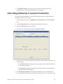
Allocating Materials in Syntera Production ______________________________________ 49
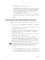
Performing Syntera Administrative Functions ____________________________________ 50
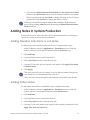
Adding Notes in Syntera Production ____________________________________________ 51
Adding Operator Instructions or Job Notes __________________________________ 51
Adding Station Notes ______________________________________________________ 51
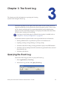
Chapter 3: The Event Log __________________________________________________________ 53
Querying the Event Log________________________________________________________ 53
Event Viewing Options_________________________________________________________ 57
Viewing Message Details ______________________________________________________ 58
Adding Comments to Messages _______________________________________________ 58
Searching the Event List _______________________________________________________ 58
Sorting Returned Events________________________________________________________ 58
Exporting Events ______________________________________________________________ 59
Purging the Event Log _________________________________________________________ 60
Chapter 4: Job Setup _____________________________________________________________ 61
Creating a New Job Setup _____________________________________________________ 61
The Settings Tab ___________________________________________________________ 62
The Selection Criteria Tab __________________________________________________ 63
Chapter 5: Data Setup ____________________________________________________________ 65
Creating a New Data Setup____________________________________________________ 65
Defining Data Input Files _______________________________________________________ 66
vi
Adding Fields _________________________________________________________________ 67
Adding Data Fields ________________________________________________________ 68
Adding Constant Fields ____________________________________________________ 70
Adding FIR Fields __________________________________________________________ 71
Adding Composite Fields __________________________________________________ 72
Adding Display Fields ______________________________________________________ 76
Changing the Order of Data Fields _________________________________________ 78
Deleting Data Setups __________________________________________________________ 78
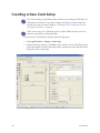
Chapter 6: Card Setup ____________________________________________________________ 79
Opening Existing Card Setups__________________________________________________ 79
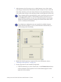
Creating a New Card Setup ___________________________________________________ 80
Creating a New Card Setup from an Existing Card Setup ________________________ 82
Defining Card Properties_______________________________________________________ 83
The Settings Tab ___________________________________________________________ 83
The Advanced Tab ________________________________________________________ 85
The Crosscheck Tab _______________________________________________________ 88
Operations Tab____________________________________________________________ 89
Runtime Composites Tab __________________________________________________ 90
Vision Verification Tab _____________________________________________________ 90
Defining Element Properties ____________________________________________________ 91
Magnetic Stripe Encode Element___________________________________________ 91
Magnetic Stripe Verify Element _____________________________________________ 92
Magnetic Stripe Read Element _____________________________________________ 93
Contact Smart Card Element ______________________________________________ 94
Contactless Smart Card Element ___________________________________________ 95
Combi Smart Card Element ________________________________________________ 97
RFID Write Element_________________________________________________________ 99
RFID Read Element ________________________________________________________ 99
Scanner Element ________________________________________________________ 100
Image Element __________________________________________________________ 101
Text Element ____________________________________________________________ 103
Barcode Element________________________________________________________ 106
UltraGrafix Language Element ___________________________________________ 109
Topcoat/Laminate Element ______________________________________________ 110
Emboss Element Properties _______________________________________________ 111
Indent Element __________________________________________________________ 113
Topping Element ________________________________________________________ 116
Laser Engraving Element _________________________________________________ 117
Label Element ___________________________________________________________ 118
Sticker Element __________________________________________________________ 119
Dynamic OCV Element __________________________________________________ 119
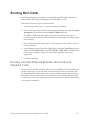
Running Mini-Cards _________________________________________________________ 121
Running Jobs that Alternate Between Mini-Cards and Standard Cards _____ 121
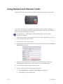
Using MasterCard Titanium Cards ____________________________________________ 122
Using Print Preview from Card Setup __________________________________________ 123
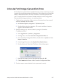
Unicode Font Image Generation Errors _______________________________________ 127
vii
Printing Card Setups _________________________________________________________ 128
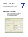
Chapter 7: Form Setup __________________________________________________________
Creating a New Form Setup__________________________________________________
The Virtual Form _________________________________________________________
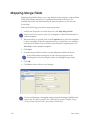
Mapping Merge Fields ______________________________________________________
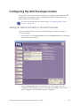
Configuring the MXi Envelope Inserter ________________________________________
Setting Up Selective Inserts on the MXi Controller __________________________
Configuring MXi in Form Setup____________________________________________
129
129
133
138
139
139
142
Chapter 8: Production Options Setup_____________________________________________ 145
Creating a New Production Options Setup ____________________________________ 145
Editing a Production Options Setup ___________________________________________ 151
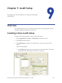
Chapter 9: Audit Setup __________________________________________________________ 153
Overview ___________________________________________________________________ 153
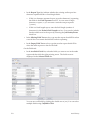
Creating a New Audit Setup _________________________________________________ 153
Chapter 10: Global Setups ______________________________________________________
Barcode Setup ______________________________________________________________
Emboss Font Setup __________________________________________________________
Adding Emboss Font or Indent Font Definitions ____________________________
Emboss Mapping Setup _____________________________________________________
Magstripe Setup ____________________________________________________________
Creating a New Magstripe Setup _________________________________________
Defining the Magnetic Stripe Properties ___________________________________
Track Map Entries________________________________________________________
Image Placement Setup _____________________________________________________
Positioning an Image File_________________________________________________
Creating a New Image Placement Setup _________________________________
Camera Setup ______________________________________________________________
Mask Setup _________________________________________________________________
OCR Font Setup _____________________________________________________________
157
157
160
160
161
162
162
163
164
165
165
166
166
167
167
Chapter 11: Stocks______________________________________________________________
Using Maxsys Stock Setups __________________________________________________
Units of Measure_________________________________________________________
Viewing Existing Stock Descriptions __________________________________________
Adding Stock Descriptions ___________________________________________________
Stock Descriptions by Type _______________________________________________
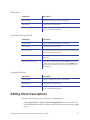
Editing Stock Descriptions ___________________________________________________
Deleting Stock Descriptions __________________________________________________
Card Stock Setups __________________________________________________________
Defining Card Stocks ____________________________________________________
Card Stock Elements_____________________________________________________
Testing Card Stock Elements _____________________________________________
169
169
170
170
171
172
177
178
178
179
180
183
Chapter 12: Smart Card Management ___________________________________________
Smart Card Management Tools ______________________________________________
Getting Started with Smart Card Management ________________________________
Crypto Device Management ________________________________________________
185
185
185
186
viii
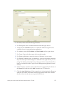
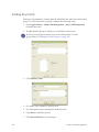
Adding a Crypto Device _________________________________________________
Deleting Crypto Devices _________________________________________________
Testing Crypto Devices __________________________________________________
Key Card Management_____________________________________________________
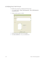
Adding Key Card Groups ________________________________________________
Adding Key Cards _______________________________________________________
Deleting Key Card Groups _______________________________________________
Deleting Key Cards ______________________________________________________
Modifying Key Card Groups ______________________________________________
Modifying Key Cards ____________________________________________________
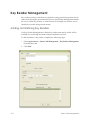
Key Reader Management ___________________________________________________
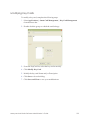
Adding and Defining Key Readers________________________________________
Deleting a Key Reader___________________________________________________
Modifying a Key Reader _________________________________________________
Resetting a Key Reader __________________________________________________
Testing a Key Reader ____________________________________________________
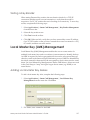
Local Master Key (LMK) Management ________________________________________
Adding Local Master Key Aliases _________________________________________
Deleting Local Master Key Aliases ________________________________________
Modifying Local Master Key Aliases _______________________________________
186
188
188
189
189
190
191
191
192
193
194
194
196
196
196
197
197
197
198
198
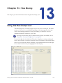
Chapter 13: Hex Dump __________________________________________________________
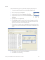
Using the Hex Dump Tool ____________________________________________________
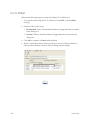
Find_____________________________________________________________________
Go To Offset ____________________________________________________________
199
199
201
202
Chapter 14: Security Configuration ______________________________________________ 203
About Security Configuration ________________________________________________ 203
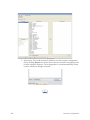
Using Security Configuration _________________________________________________ 204
Chapter 15: Export Setups _______________________________________________________ 207
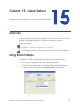
Overview ___________________________________________________________________ 207
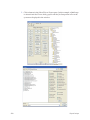
Using Export Setups _________________________________________________________ 207
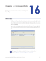
Chapter 16: Keyboard Entry _____________________________________________________ 211
Overview ___________________________________________________________________ 211
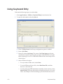
Using Keyboard Entry________________________________________________________ 212
Chapter 17: Back Up and Restore________________________________________________
Backing Up and Restoring the System ________________________________________
Dropping Unnecessary Database Tables __________________________________
Create the Backup ______________________________________________________
Validating the Backup Image ____________________________________________
Restoring the System_____________________________________________________
215
215
215
216
217
217
Appendix A: Miscellaneous Configuration _______________________________________
Configuration of Services ____________________________________________________
User Configuration __________________________________________________________
Audit Settings _______________________________________________________________
Anti-Virus ___________________________________________________________________
Network Security ____________________________________________________________
219
219
220
220
221
221
ix
Microsoft Windows Updates__________________________________________________ 221
Managing the Password for the Datacard System Default User Name __________ 222
Font Mapping/Datacard Converted Fonts ____________________________________ 224
Appendix B: Vision Verification Module __________________________________________
Introduction ________________________________________________________________
Quick Stock Capture ________________________________________________________
Card Stock Setup with a Pattern Match Element_______________________________
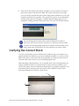
Verifying the Correct Stock __________________________________________________
Verifying Card Stock _____________________________________________________
Vision Registration _______________________________________________________
Verifying Correct Personalization_____________________________________________
Quality Assurance and Checking ____________________________________________
Font Creation Process _______________________________________________________
227
227
229
230
235
236
239
239
240
241
Appendix C: Artista VHD Module ________________________________________________
Introduction ________________________________________________________________
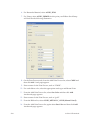
Ribbon Stock Setup _________________________________________________________
Card Setup _________________________________________________________________
243
243
243
245
Appendix D: Resource Editor Translation Tool _____________________________________
Overview ___________________________________________________________________
Creating or Modifying User Translations _______________________________________
Tip Sheet ___________________________________________________________________
249
249
249
255
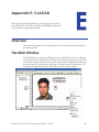
Appendix E: ConCAD ___________________________________________________________
Overview ___________________________________________________________________
The Main Window ___________________________________________________________
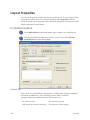
Layout Properties____________________________________________________________
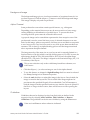
Front/Back Surface ______________________________________________________
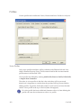
Profiles __________________________________________________________________
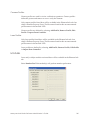
Modules ________________________________________________________________
Grid Guidelines__________________________________________________________
Compatibility____________________________________________________________
Menus ______________________________________________________________________
File _____________________________________________________________________
Edit _____________________________________________________________________
Element_________________________________________________________________
Extras ___________________________________________________________________
View ____________________________________________________________________
The Toolbar _________________________________________________________________
Buttons _____________________________________________________________________
The Element Property Window________________________________________________
Element Tab Definitions ______________________________________________________
Element Info Tab ________________________________________________________
Processing Tab __________________________________________________________
Bitmap Settings Tab______________________________________________________
BMP Laser Details ________________________________________________________
Verification Tab _________________________________________________________
Filter Tab ________________________________________________________________
257
257
257
258
258
260
261
262
262
263
263
264
264
264
265
266
267
267
267
267
268
269
270
272
273
x
Bitmap Image Element __________________________________________________
Bitmap Text Element _____________________________________________________
Solid Box Element________________________________________________________
Wedge Element _________________________________________________________
Vector Settings Tab ______________________________________________________
Vector Line Element _____________________________________________________
Vector Rectangle Element _______________________________________________
Vector Circle Element ___________________________________________________
Vector Ellipse Element ___________________________________________________
Vector Beziér Spline Element _____________________________________________
Vector Text Element _____________________________________________________
Vectorized (TTF) Text Element_____________________________________________
Perforated Number Element _____________________________________________
Barcode Element Tab____________________________________________________
2D Barcode Element_____________________________________________________
276
277
279
279
280
281
281
282
282
283
283
284
285
286
287
Appendix F: Ring Search Vision Profiles __________________________________________
Introduction ________________________________________________________________
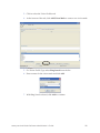
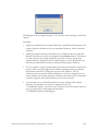
Setting Up a Ring Search Vision Profile ________________________________________
Loading Images _________________________________________________________
Defining and Testing Search Parameters __________________________________
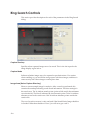
Ring Search Controls ________________________________________________________
Image Capture _____________________________________________________________
Ring Search Target Design ___________________________________________________
Search Algorithm ___________________________________________________________
289
289
290
292
294
304
306
307
309
xi
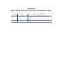
Revision Log
Maxsys and MX Series Card Issuance Systems Administrator’s Guide
Revision
Date
Description of Changes
A
April 2011
First release of this document with software
version 5.6.
B
July 2011
Updated for feature changes at version 5.6 SP2
xii
Chapter 1: About the
Software
This chapter provides an overview of the Datacard® Maxsys®,
and MX Series (MX6000™, MX2000™, and MX1000™) card
issuance system software interface.
Introduction
The Controller software program is the production interface for the Maxsys and
MX Series card issuance systems.
The MX6000, MX2000 and MX1000 systems will be referred to as MX Series
systems in this manual.
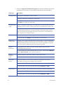
This system software program is designed for administrators and operators who
run production jobs, work with setups, and/or manage system components.
Multiple applications make up the system software including applications that
handle interface customization, production, configuration, and administration.
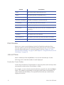
The menu and tools are listed below.
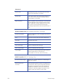
Application
Description
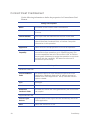
Tools
The Tools menu contains the Production Preferences tool,
which allows the customization of display elements in the
production interface.
Production
The Production Station contains status bars and four tabs.
•
•
•
•
Event Log
Ready Jobs Tab
Production Tab
All Jobs Tab
Job Details Tab
The Event Log contains a tool bar and a tools menu with the
following commands:
•
•
•
•
Query Event Log
Export Event
Purge Events
Event Log Preferences
Maxsys and MX Series Software Administrator’s Guide
1
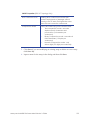
Application
Description
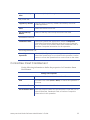
Setups
The Setups menu contains the following setups:
•
•
•
•
•
•
Global Setups
Card Setup
Form Setup
Production Options Setup
Audit Setup
Barcode Setup
Emboss Font Setup
Emboss Mapping Setup
Magstripe Setup
Image Placement Setup
Camera Setup
Mask Setup
OCR Font Setup
Card Stock Lookup Setup
Vision Filter Setup
The Stocks menu contains the Stock Management tool and
setup tools for cards, forms, labels, ribbons, and other stocks.
•
•
•
•
•
•
•
•
•
•
•
•
•
2
Data Setup
Global Setups are often used across multiple modules or
applications within the software. Global setups include the
following:
•
•
•
•
•
•
•
•
•
•
Stocks
Job Setup
Stock Management
Card Stock Setup
Cleaning Tape Stock Setup
Color Ribbon Stock Setup
Form Stock Setup
Indent Ribbon Stock Setup
Label Stock Setup
Monochrome Ribbon Stock Setup
Retransfer Stock Setup
Retransfer Stock Set Setup
Roller Stock Setup
Topcoat Stock Setup
Topping Foil Stock Setup
About the Software
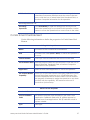
Application
Description
Smart Card
Management
The Smart Card Management menu contains the tools used
in smart card operations.
•
•
•
•
Utilities
Key Card Management
Key Reader Management
Local Master Key Management
The Utilities menu contains tools for working with data files,
diagnostics for Controller and modules, security
configurations, exporting setups, localization tools, and
vision utilities.
•
•
•
•
•
•
•
Help
Crypto Device Management
Hex Dump
Diagnostics
Security Configuration
Export Setups
Keyboard Entry
Change Locale
Vision Utilities
The Help menu contains error messages, software patch
information, and context-sensitive help.
• Help
• Error Messages
• About the Software (Patch Information)
Diagnostics are generally not documented in this manual. Trained personnel
can access Diagnostics information in the module service manuals.
Simulator Setup will appear on the Utilities menu when Machine Simulator
software is installed. For information on this utility refer to the Datacard
Maxsys/MX Series/PB6500 Machine Simulator Installation and Configuration
Guide (Part No. 539789-xxx).
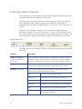
Production
The Production Station is the heart of the Datacard high-speed production
environment. The following sections describe the production interface. For
information on using Production to perform tasks, refer to Chapter 2:
“Production” on page 27.
Maxsys and MX Series Software Administrator’s Guide
3
Production Station Interface
The components of the Production interface include upper and lower status bars
and tabs that display information on Job screens.
The upper and lower status bars can be viewed regardless of the tab displayed.
The components differ slightly depending on whether the workstation is
integrated with the Syntera program (refer to “Enabling the Syntera Interface” on
page 5).
Elements of the Production interface can be customized using Production
Preferences (refer to “Production Preferences” on page 19). Fonts and font sizes
for tool bars, tables, and other elements can be customized for each operator. FIR
data views and tooltips can be activated to appear at the bottom of Job screens.
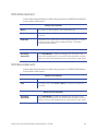
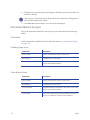
Upper Status Bar
The upper status bar on a Maxsys/MX Series Production application contains the
following:
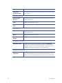
Indicator
Description
Load (and Cancel)
buttons and the load
status bar
The Load button loads a job into the database. One job can be
loaded at a time. The Load status bar gives a visual percentage
of the job loaded. A Cancel button stops the job loading process.
Production status bar
The Production status bar gives a visual percentage of job
completion as well as the speed (in cards-per-hour) of the job.
Machine state status
The Machine state monitor provides the current state of the
system. The machine states are as follows:
4
Idle
There is no activity in the system.
Pausing
Production is in the process of pausing.
Paused
Production has paused.
Stopping
Production is in the process of being stopped.
Busy
The system is in the production process.
Offline
The system has been taken offline or
production is initializing.
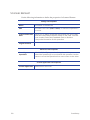
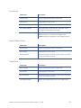
About the Software
Indicator
Description
Open Hood status
Indicates whether it is OK to open the hood.
Audit status information
Indicates whether audit data is being collected.
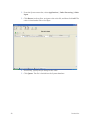
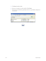
Lower Status Bar
The lower status bar has program tabs on the left side that display all open
applications. In the example shown below, the Production interface, Event Log
Viewer, and Job Setup applications are currently open. Clicking on a Tab will
bring that application window to the top.
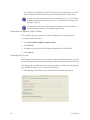
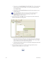
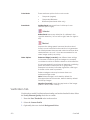
Enabling the Syntera Interface
For sites that use both Maxsys/MX Series and the Datacard® Syntera®
Manufacturing Efficiency System, the Syntera system is integrated into the
Maxsys/MX Series Production application. This allows Syntera jobs to be run on
a Maxsys/MX Series machine if needed.
To enable or disable the Syntera interface, follow these steps:
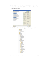
1. Select Applications | Utilities | Diagnostics.
2. Select Controller in the left pane.
3. Under the Controller Configuration Editor tab, double-click System in the
list to expand it, and then expand Syntera Interface.
4. Under Syntera Interface, select Syntera Interface Enabled and then set the
value to true on the top bar by double-clicking the false value and selecting the
option button in the pop-up box. (To disable the Syntera interface, reset the
value to false.)
Close and restart the program for the changes to take effect.
When Syntera is enabled, toggle between the two programs by clicking the button
on the toolbar.
Maxsys and MX Series Software Administrator’s Guide
5
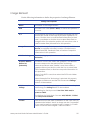
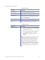
Syntera-Integrated Upper Status Bar
If the Production application is integrated with Syntera, the upper status bar
contains the following information:
Load status bar and
Cancel load button and
the load status bar
The Load button is used to load a job into the database. One job
can be loaded at a time. When a job is being loaded, the Load
status bar gives a visual percentage of the job loaded. A Cancel
Load button allows the job loading process to be stopped.
Production status bar
The Production status bar gives a visual percentage of job
completion as well as the speed (in cards-per-hour) of the job.
Open Hood status
The Open Hood status monitor simply indicates whether opening
the hood is allowed (OK to Open Hood or Do Not Open Hood).
Audit status information
Indicates whether audit data is being collected (On and green) or
not (Off).
Syntera button
This button can be used to view the Syntera management screens.
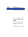
Machine state status
The Machine state monitor provides the current state of the
system. The machine states are as follows:
Idle
There is no activity in the system.
Pausing
Production is in the process of pausing.
Paused
Production has paused.
Stopping
Production is in the process of being stopped.
Busy
The system is in the production process.
Offline
The system has been taken offline or
production is initializing.
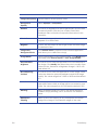
User Logged in
Name of user currently logged in to the application.
Start/Pause/Stop/Stop
(No Pick)/Abort/Display
Fields
Use the Start button to initiate the process. Use the Pause/Stop/
Stop (No Pick)/Abort buttons to pause, stop, or abort the
production run. Use the Display Fields button to display fields from
the job.
Machine Job Setup
Indicates the Job Setup.
Mode
Use Mode to select the type of records to run (Cards, Forms, Cards
and Forms, etc.).
6
About the Software
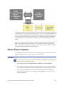
Syntera Toolbar Shortcut Icons
The Syntera interface also contains a group of icons under the upper status
bar. These icons provide a quick shortcut for many functions, such as splitting
jobs, loading jobs, and viewing job details. Icons that are grayed-out on the
screen are not currently applicable.
Split - Starts splitting the selected job
Allocate - Displays list of allocated materials
Pausing
Refresh - Refreshes the screen
Release - Releases a selected job
ming
Resu
Stopping
Admin - Administrator logon
Job Notes - Adds job notes
Accept - Accepts a selected job
Decline - Declines a selected job
View Details - Displays job details
Load - Starts loading jobs
Station Notes - Adds station notes
Materials - Displays the bill of materials
Ready Jobs Tab
The Ready Jobs tab is not available on the Syntera interface.
The Ready Jobs tab displays the Ready Jobs screen in the Production interface,
which contains a table of all loaded jobs that have not been run or that have at
least one rejected card.
Right-clicking on a job brings up a menu with options for opening the
corresponding Job Setup, Card Setup, Data Setup, or Audit Setup (if applicable)
or access to the Export Setups utility or View Data for that field. For more
Maxsys and MX Series Software Administrator’s Guide
7
information on displaying jobs, refer to "Choose Columns to Be Displayed" on
page 17 and “Job Grouping by Input File” on page 18.
Depending on the fields defined in Data Setup and the columns selected, the
following information may be available for each job:
Column
8
Description
Name
The name of the job
Split Number
If the job has been split, the resulting jobs are sequentially
numbered.
First/Last Record
Displays the first/last record in the job or if the job is split, the first/
last record of the split job.
Total Cards
The total number of cards in the job
Good Cards
The number of good cards in the job (supplied only if the job has
been run and had rejects)
Reject Cards
The number of rejected cards (supplied only if the job has been
run)
Held Cards
Number of held cards (cards that will not be processed)
Status
The status of the item: None, Good, or Rejected
Input FIle
The Input file used for this job
Job Setup
The Job Setup file used for this job
Total Forms
The total number of forms in the job
Good Forms
The number of good forms in the job (supplied only if the job has
been run and had rejects)
Reject Forms
The number of rejected forms (supplied only if the job has been
run)
Held Forms
Number of held forms (forms that will not be processed)
Group Name
The name of the group
Card Setup
The Card Setup file used for this job
Form Setup
The Form Setup being used for this job
Data Setup
The Data Setup file used for this job
Audit Setup
The Audit Setup file used for this job
Created
The date the job was created
Last Worked On
The date on which the job was last used or modified
Syntera ID
The Syntera ID number, if any, assigned to the record
About the Software
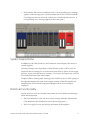
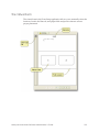
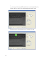
Production Tab
The Production tab provides a visual representation of the entire system and
system status messages. Elements of the production interface can be customized
using Production Preferences from the Tools menu (refer to “Production
Preferences” on page 19).
Clicking on a cell in the table will bring up extended help. Right-clicking on a cell
in the table brings up a menu with the View Data command.
This production screen is the main interface for viewing (in real-time) the
system's status while jobs are running. The system supply status is indicated by a
scale on the right side of the virtual supply.
On a standalone Maxsys/MX Series Production interface (without Syntera
integrated), the Production screen has buttons to start, stop or pause production,
or remake jobs. (With Syntera integrated, these buttons are on the upper status
bar of any job screen.)
Maxsys and MX Series Software Administrator’s Guide
9
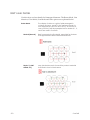
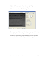
A Visual Representation of the System
Each module in the system is represented in graphic form. A color coding system
displays the status of each module.
10
•
Blue indicates normal operating status. Any informational messages
concerning normal operation appears in the lower message pane.
•
Yellow indicates that a cautionary condition exists (low supplies, input card
tray approaching empty, etc). A corresponding caution message appears in
the message pane.
About the Software
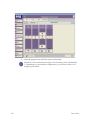
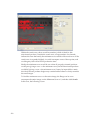
•
Red indicates that an error condition exists. A corresponding error message
appears in the message pane. (In the example below, the Controller and the
Card Input module are red in the virtual view, which indicates an error. A
corresponding error message appears in the lower pane.)
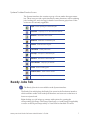
System Supply Status
In addition to the other functions, the Production screen displays the status of
system supplies.
Card trays change color depending on their fill state (white, yellow, red). An
Input tray that is running low on cards turns from white to yellow as the supply
gets low, and to red when the tray is empty. Conversely, an Output tray is shown
as red when full and white when empty.
Graphics ribbon, cleaning tape, and topper foil each have an icon with a gauge at
the right that displays the state of the supply quantity. When the supplies are
exhausted, the icon in the message pane changes and an error message is
displayed.
Roll-Over Functionality
Use the mouse to roll over selected components and view details and messages
about that component.
•
Roll over modules to view the most recent message related to that module.
(This duplicates the information seen in the message pane.)
•
Roll over supply icons to see the type and status of the supplies.
Maxsys and MX Series Software Administrator’s Guide
11
All Jobs Tab
The All Jobs tab displays the Production All Jobs screen, which contains a list of
all loaded jobs, of any status.
Depending on the fields defined in Data Setup and the columns selected, the
specific information that may be available for each job is listed below. (To change
the columns displayed, refer to "Choose Columns to Be Displayed" on page 17
and to use the Job Grouping feature, refer to “Job Grouping by Input File” on
page 18.)
The job information will vary slightly with a Syntera integrated interface.
Maxsys/MX Series Interface
Under the All Jobs tab, the columns available for a Maxsys/MX Series Production
interface are as follows:
Column
12
Description
Job Group
The name of the job group
Name
The name of the job
Split Number
If the job has been split, the resulting jobs are sequentially
numbered.
First/Last Record
The first/last record in the job. If the job is split, the first/last
record of the split job is displayed.
Total Cards
The total number of cards in the job
Good Cards
The number of good cards in the job (supplied only if the
job has been run and contained rejects)
Reject Cards
The number of rejected cards (supplied only if the job has
been run)
Held Cards
Number of held cards (cards that will not be processed)
Status
Job status
Input FIle
The Input file used for this job
Job Setup
The Job Setup file used for this job
Total Forms
The total number of forms in the job
Good Forms
The number of good forms in the job (supplied only if the
job has been run and contained rejects)
Reject Forms
The number of rejected forms (supplied only if the job has
been run)
About the Software
Column
Description
Held Forms
Number of held forms (forms that will not be processed)
Card Setup
The Card Setup file used for this job
Form Setup
The Form Setup used for this job
Data Setup
The Data Setup file used for this job
Audit Setup
The Audit Setup file used for this job
Created
The date the job was created
Last Worked On
The date on which the job was last used or modified
Syntera ID
The Syntera ID number, if any, assigned to the record
Syntera Interface
On the Syntera-integrated Production interface, the All Jobs tab provides the
following information:
•
The My Work tab lists jobs that are accepted, loaded, or ready to be loaded.
•
The Pooled tab lists jobs that are queued but not yet accepted or loaded.
To move jobs from the Pooled tab to the My Work tab:
1. Select the Pooled tab.
2. Select the job(s) to accept.
3. Click Accept on the toolbar. The jobs move to the My Work folder.
Under both the My Work and Pooled tabs, the following columns may be
available for each job:
Column
Description
Job ID
The ID number of the job
Name
The name of the job
Due Date
The date by which the job must be completed
State
The current state of the job (Ready, Failed, Loading, etc.)
Cards
The total number of cards in the job
Good Cards
The number of good cards in the job (supplied only if the
job has been run and contained rejects)
Reject Cards
The number of rejected cards (supplied only if the job has
been run)
Maxsys and MX Series Software Administrator’s Guide
13
Column
Description
Forms
The total number of forms in the job
Good Forms
The number of good forms in the job (supplied only if the
job has been run and contained rejects)
Reject Forms
The number of rejected forms (supplied only if the job has
been run)
Priority Type
The priority of the job
ProcessStepName
The process name given to the job (for example,
MaxsysProduction)
Created
The date the job was created
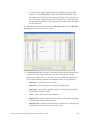
Filtering Tool
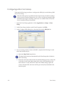
The All Jobs tab also includes a filtering tool for quickly locating jobs based on
their parameters. Use the filtering tool to define specific criteria that will speed up
the search.
To search for jobs:
1. In the left pane, select the check box next to any or all of the parameters to use
in the search. The search filter parameters are listed below. The more
parameters selected, the narrower the scope of the search. Enter the required
information for each parameter selected.
2. Click Search. The top area of the left pane changes to reflect search
parameters.
Click Clear to clear all parameters and display all jobs in the system.
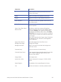
Search Filter Parameter
14
Description
Name
Enter the name of the job in the text box.
Status
Select the status from the list. The program displays
only those jobs with the selected status.
Total Cards
Total cards in the job. Enter a number in the text
box and select a quantitative indicator (less than,
more than, equal to, etc.) from the list.
Example: For example, enter 500 and select >=
from the list. Only jobs that have 500 or more cards
are displayed.
About the Software
Search Filter Parameter
Description
Due Date (Syntera only)
Enter the date range to search within.
Created (not available
on Syntera)
Enter a number in the text box and then select
Hours or Days from the list. For example, enter “5”
in the text box and select “Days” from the list, the
program displays only those jobs created in the
past five days.
Last Worked On (not
available on Syntera)
Enter a number in the text box and then select
Hours or Days from the list.
Example: Enter “8” in the text box and select
“Hours” from the list, the program displays only
those jobs worked on during the past eight hours.
Job Setup (not available
on Syntera)
Select Browse, and then select a Job Setup from
the dialog box. The program displays only those
jobs that use the selected Job Setup.
Input File (not available
on Syntera)
Enter the Input File name into the text box. The
program displays only those jobs that use the listed
Input File.
Has Rejected Products
If selected, the program displays only jobs that
contain rejected products.
Has Held Products
If selected, the program displays only jobs that
contain held products.
Machine Setup (Syntera
interface)
Select a machine setup value from the list.
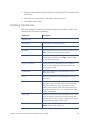
Job Details Tab
The Job Details tab in the Production area provides information to monitor (in
real time) the status of individual cards within a job.
Depending on the fields defined in Data Setup and the columns selected, the
following information may be available for the job. (To change the columns
displayed, refer to "Choose Columns to Be Displayed" on page 17.)
Information that may be available under the Job Details tab is as follows:
Column
Description
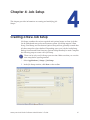
Record Number
The number of the record within the job
Type
The type of record (card or form)
Maxsys and MX Series Software Administrator’s Guide
15
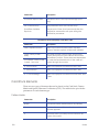
Column
Description
State
The current state (Unprocessed, etc.)
Status
Job status (Ready, Completed, etc.)
Held
Number of held cards (cards that will not be processed)
Number of Attempts
Number of attempts to process the job
Card Setup
The Card Setup file used for this job
Form Setup
The Form Setup file used for this job
Data Setup
The Data Setup file used for this job, as defined in the
Job Setup
Audit Setup
The Audit Setup used for this job, if any
Created
The date the job was created
Last Worked On
The date on which the job was last used or modified
Syntera ID
The Syntera ID number, if any, for the record
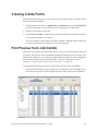
Print Preview
Select one or more records displayed in the Job Details tab and select Print
Preview option to preview the selected records (print preview is also available
from the right-click menu). For more information, refer to Chapter 2: “Print
Preview from Job Details” on page 39, and Chapter 6: “Using Print Preview from
Card Setup” on page 123.
Job List Pane
Select a loaded job from the Job List to view records from that job. Use the
following tools to limit the number of cards displayed.
Production Counts Folders
Use the list of Production Counts folders to select only those cards in the job that
meet specific criteria such as Good, Reject, or Held.
For example, to view only the rejected cards from a specific job, select the Reject
folder. (The number in parentheses to the right of the folders is the number of
cards contained in that folder.) The rejected card from this job would then be
displayed in the list.
16
About the Software
Filter Tool
If the selected job contains a large number of cards, use the filter tool to limit the
number of cards displayed. The tool consists of a list of record numbers and range
parameters at the bottom of the Job List pane.
For example, to view records 2700 to 2800 of a job that contains 10,000 cards,
select Record No. from the list, enter the range (2700, 2800) in the Single Value or
Range boxes, and then click Search. Click Clear to clear the search results and
display the full job details.
To search for a single record, select Record No. from the list and then enter the
record number in the first of the two range fields and click Search. Click Clear to
clear the search results and display the full job details.
Filtering categories (record number, state, status, etc.) are defined in the
Data Setup.
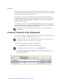
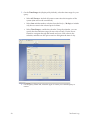
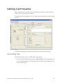
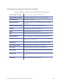
Choose Columns to Be Displayed
Use Choose Columns to select the columns to be displayed on the Ready Jobs, All
Jobs, or Job Details tabs of the Production station.
Privileges for this option may be defined when security is enabled; refer to
Chapter 14: “Security Configuration” on page 203.
Perform the following steps to view or hide columns:
1. Select the Ready Jobs, All Jobs, or Job Details tab.
For Syntera-enabled workstations, select the Job Details tab.
2. Click Choose Columns (or Columns for Syntera-enabled workstations) on
the bar above the job list.
Maxsys and MX Series Software Administrator’s Guide
17
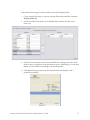
3. In the Available Columns box, select the column(s) to display and click Add >
or Add All >>.
4. In the Selected Columns box, select the column(s) not to display and click <
Remove or << Remove All.
Select multiple column types using Shift+Click or Alt+Click.
5. Use Set to Default to return to the default setting.
6. Click OK when finished, or Cancel to exit without making changes.
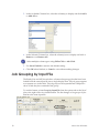
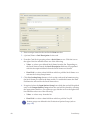
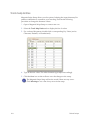
Job Grouping by Input File
The Ready Jobs and All Jobs tabs have a feature that groups jobs that have been
loaded from the same input file into a single display item. The job group appears
as a separate row in the table. The job group can be expanded and collapsed to
show or hide the jobs contained in the group.
To use this feature, select Group by Input File from the options above the list of
jobs to the right of the view details button. The list changes to list groups of jobs
that have the same input file.
18
About the Software
If an input file is loaded multiple times, all jobs that use this file will
be grouped together, whether they are related or not.
Job groups are displayed in sorted order (alphabetical by input file name). The
sort indicator control in the Input File column can be used to reverse the order of
the groups. Within each job group, the jobs are initially sorted by create time but
may also be sorted by other fields.
Click on a folder in the list to expand or collapse that folder. Click on the toolbar
to expand or collapse all job groups.
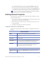
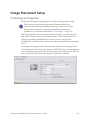
Production Preferences
Production Preferences contains tools to customize the appearance of elements in
the Production station interface for easier viewing. Customization can include the
text in tables, tabs, buttons, toolbars, and extended help. There is also a setting for
viewing FIR record data in the interface with customized sizing and tooltip
option.
Production preferences are set and stored for each operator. To use the
Production Preferences Tool, select Tools | Preferences from the menu bar.
Each tab in the tool has options for customizing Production interface elements
(font, font size, FIR data, and tooltip views). Each tab has the following buttons:
OK - Saves and applies the changes and closes the dialog.
Cancel - Closes the dialog.
Apply - Saves and applies the changes and leaves the dialog open for additional
changes.
Use Defaults - Resets all settings to the default.
Maxsys and MX Series Software Administrator’s Guide
19
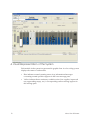
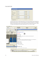
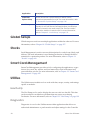
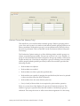
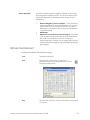
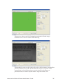
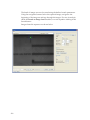
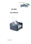
General Tab
Use the General tab to set the font and font size for the elements in the Production
Station interface tabs (1 in the following figure), Production Statistics (2), Display
Fields (3), Extended help titles and text (4), optionally enable and customize Table
Tooltips (5) that appear when the pointer hovers over a cell in a table.
1
2
4
3
5
20
About the Software
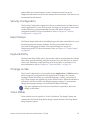
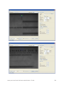
Toolbars Tab
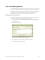
Use the toolbar tab to set the font and font size for the toolbar buttons (1 in the
following figure) on the Production interface tabs and View Accounts dialog.
Toolbars can be set individually or with common settings for all toolbars.
1
Tables Tab
Use the Tables tab to set the font and font size for the tables on the Production
interface tabs and View Accounts dialog.
Maxsys and MX Series Software Administrator’s Guide
21
The font and font size changes apply to the table column headings and table
values (1 in the following figure). Tables can be set individually or with common
settings for all tables.
1
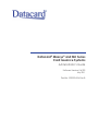
FIR Record Tab
Use the FIR Record tab to enable FIR data to display at the bottom of the
Production interface tabs with customized sizing and tooltip option. The font and
font size can be set for the FIR data view as well as the tooltip. Preferences can be
set for each tab individually or with common settings for all tabs.
22
About the Software
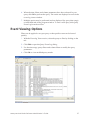
Event Log
Use the Event Log tools to query and view system events. System events are
logged automatically as the system and software program operates. These events
can be viewed and analyzed for system administration and troubleshooting
purposes. Events returned by the query display in tabbed lists that can be saved
for later viewing or archiving. For more information, refer to Chapter 3: “The
Event Log” on page 53.
Setups
The Setups component includes several applications to create, edit, and delete
various types of setups used in jobs processed on the system.
Application
Description
Job Setup
Create or edit Job Setups used to process cards with the
Job Setup application. Select the various required and
optional setups to form a job that can be loaded and run on
the Maxsys or MX Series System. For more information, refer
to Chapter 4: “Job Setup” on page 61.
Data Setup
Data Setups tell the system how to interpret the input data.
The Data Setup provides information such as the order of
the input data fields and the code or position that identifies
the beginning and end of each data field. The system uses
this information to parse the data stream into the format
used for production. For more information, refer to Chapter
5: “Data Setup” on page 65.
Card Setup
The Card Setup application is used to define and modify
card parameters. A Card Setup defines an individual card
that has certain properties and contains certain element
sets (label, image, overlay, etc.). For more information, refer
to Chapter 6: “Card Setup” on page 79.
Form Setup
The Form Setup application is used to create and modify
card delivery forms. Control the layout of the form by
selecting pre-configured form templates and then
positioning the cards on the form. In addition, select and
format the fields that will appear on the forms and associate
the form with a Data Setup. For more information, refer to
Chapter 7: “Form Setup” on page 129.
Maxsys and MX Series Software Administrator’s Guide
23
Application
Description
Production
Options Setup
Use the Production Options Setup to define various
operational parameters for a job. For more information, refer
to “Production Options Setup” on page 145.
Audit Setup
The Audit Setup prepares the system to run audit reports
primarily for use with Smart Card applications. Audit Setups
define a format for the audit output file. The file contains
production statistics for each card. For more information,
refer to Chapter 9: “Audit Setup” on page 153.
Global Setups
Global setups are used across multiple applications within the software. For more
information, refer to Chapter 10: “Global Setups” on page 157.
Stocks
Stock Management is used to store stock descriptions for cards, forms, labels, and
ribbons. The stock information is used during production to identify the bill of
materials for a particular product. For more information, refer to Chapter 11:
“Stocks” on page 169.
Smart Card Management
Smart Card Management provides tools for configuring the applications, crypto
devices, key cards, key readers, and local master keys used in the smart card
personalization process. For more information, refer to Chapter 12: “Smart Card
Management” on page 185.
Utilities
The Utilities menu includes tools to work with data, setups, security, and settings
specific to modules.
Hex Dump
The Hex Dump tool is used to display the raw text code in a data file. This data
can be searched to troubleshoot problems that may cause errors during
Production. For more information, refer to Chapter 13: “Hex Dump” on page 199.
Diagnostics
Diagnostics is a tool on the Utilities menu within applications that allows an
authorized administrator to perform tasks and adjust settings for the Controller
24
About the Software
and modules in a central issuance system. Trained personnel can access
Diagnostics information in the service manuals for each module. This menu is not
documented in this manual.
Security Configuration
The Security Configuration application allows an administrator to limit access to
certain applications or areas of the system. Privileges are assigned to users based
on their Windows group membership created in the Windows group
configuration utility. For more information, refer to Chapter 14: “Security
Configuration” on page 203.
Export Setups
The Export Setups utility allows bundling Setups and other related files for use in
transferring between systems, facilities, and for use by Datacard service
personnel in debugging problems. The exported Setups are saved in a
compressed zip file. For more information, refer to Chapter 15: “Export Setups”
on page 207.
Keyboard Entry
The Keyboard Entry utility allows job creation without an input data file. Sample
data can be entered manually using the keyboard or by file reference in order to
create a job. Manually created jobs may be reviewed prior to production. For
more information, refer to Chapter 16: “Keyboard Entry” on page 211.
Change Locale
The Locale Configuration tool (opened from the Applications | Utilities menu)
allows temporary configuration of the applications to display in a selected
language. Within this dialog you select the language, country, and variant (if
any). These changes are applied only to the current session. When the interface is
restarted, it will revert back to the default language settings. To permanently
change the language settings, use the Windows Regional settings.
Any open applications must be closed and then re-opened for the locale
change to take effect.
Vision Utilities
These utilities are tools specific to Vision Verification. The Image Capture tab
contains the Card Stock Setup Based Image Capture and the Card Setup Based
Image Capture options.
Maxsys and MX Series Software Administrator’s Guide
25
Software Information
Error Messages
A list of error messages is available by selecting Help | Error Messages. Error
messages are categorized by module and have unique message numbers. A
printable list of all error messages is published on the Administrator’s library.
Software Version and Patch Information
Software version, copyright, and patch information is available by selecting Help
| About. To display an overview of any patches installed to the software, select
Patch Information on the bottom of the About screen.
The patch overview displays the number of patches applied and patch
descriptions with information about the problems that were fixed by the patch.
Fonts
Datacard recommends TrueType fonts for graphics printing, which are loaded
through Windows via the Control Panel. Type 1 fonts (PFB and PFM) can also be
used, but they must be copied into the C:\MX6000\lib\jre\lib\fonts directory.
Maxsys/MX Series systems do not support Windows Bit Mapped Fonts (e.g.
FON files) or OpenType® Fonts.
Security
Maxsys/MX Series administrators are able to remove write access to the
C:\Maxsys (or MX6000, MX2000, or MX1000) path for most operators. However,
some situations still exist where operators must have write access to certain parts
of the path. For more information, refer to Chapter 14: “Security Configuration”
on page 203.
26
About the Software
Chapter 2: Production
This chapter provides procedures for working with jobs in the
Production application, including loading job files, viewing and
running jobs.
The Production station is the heart of the Datacard high-speed production
environment. This application allows you to perform the following tasks.
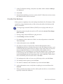
•
Monitoring production
•
Stopping jobs
•
Loading jobs
•
Retrieving audit reports for jobs
•
Running jobs
•
Splitting jobs
•
Viewing jobs
•
Filtering and searching for jobs
•
Viewing cards/forms
•
Holding/removing products from jobs
•
Remaking jobs
•
Deleting jobs
Monitoring Production
Production can be monitored from various areas in the Production interface:
•
The upper status bar on the main interface has load status, production status,
and machine state monitors that give visual indicators of job and machine
states. (For more information, refer to "Production Station Interface" on
page 4.)
•
The Production tab provides a visual representation of the entire system, as
well as the capability to monitor the supply status. (For more information,
refer to "Production Tab" on page 9.)
•
You can also monitor the status of individual cards within a job from the Job
Details tab. The Job Details tab displays a table with information about each
product in the currently-selected job. To reduce the number of products
displayed, select a filter in the left pane. (For more information, refer to "" on
page 14.)
Maxsys and MX Series Software Administrator’s Guide
27
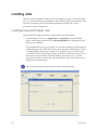
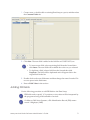
Loading Jobs
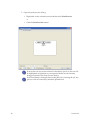
After the Load command is started, the Load dialog box opens. From this dialog
box, you can load jobs into the database for the Maxsys/MX Series modules. You
can also load Syntera jobs and CardSystem Manager (CSM) jobs. These
procedures are provided below.
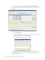
Loading Maxsys/MX Series Jobs
Perform the following procedure to load job files into the database.
1. In the Production window (Applications | Production), click the Load
button on the upper status bar. The Maxsys/MX6000 tab is displayed on the
dialog box by default.
The program allows you to pool jobs. You can select multiple job files that are
loaded contiguously. When this is done, the load status identifies the job that
is loading and its percentage complete. For example, if you load three jobs
you will see the job load progress bar go from 0% to 100% three times. If you
want to know the job that’s currently loading, hover the cursor over the
progress bar and you will see the job name in the tooltip. (This feature is not
supported for Syntera jobs.)
All selected input files must be able to use the same Job Setup.
28
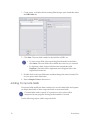
Production
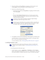
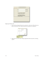
2. Select the job file by clicking Browse, navigating to the file location, and
clicking Open. The file path appears in the File Name text box.
3. Perform one of the following steps.
•
Select the Job Setup file by clicking Browse, navigating to the file location,
and clicking Open.
or
•
Select the Use Selection Criteria check box to let the program search
through existing Job Setups (that contain the selection criteria) to find a
name that matches the job file.
Job Setups specify which Data Setups, Production Options Setups,
Audit Setups, and Card Setups the job will use.
Jobs that appear in the Ready Jobs and All Jobs tab have, depending on
security privileges of the user, a right click menu with options to open
the setups used, view the data and to export the job setups.
4. Click Load to load the job into the database. The job appears in the Ready Jobs
and All Jobs lists. You can view the load status monitor on the upper status
bar to see the load completion percentage.
To run a loaded job, refer to "Running Maxsys/MX Series Jobs" on page 36.
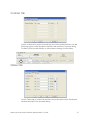
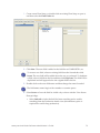
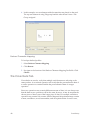
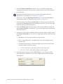
Loading Syntera Jobs
Syntera jobs can be loaded only if the Syntera software is installed and
enabled on the workstation. (Refer to "Enabling the Syntera Interface" on
page 5.)
To load Syntera jobs, follow these steps:
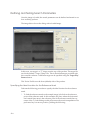
1. In the Production window (Applications | Production), click the Syntera
button on the upper status bar. If you do not see a Syntera button, verify that
the Syntera interface is enabled. If necessary, log in to the Syntera program.
Maxsys and MX Series Software Administrator’s Guide
29
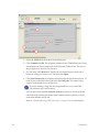
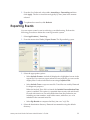
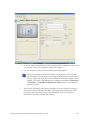
2. From the Syntera menu bar, select Applications | Order Processing | Order
Input.
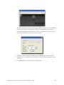
3. Click Browse in the toolbar, navigate to the order file, and then click Add. The
order is listed under Files to be Input.
4. If necessary, specify the Job Setup for the order.
5. Click Queue. The file is loaded into the Syntera database.
30
Production
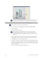
6. From the Syntera menu bar, select Applications | Production Planning |
Basic Job Creation. The job order you queued is listed under Available Work
(Orders).
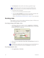
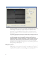
7. Select the job order from the list and complete one of the following:
•
Click Create And Queue.
•
Click Create Job(s). Once the order is displayed in the Unqueued Jobs list,
select the order from that list and click Queue Job.
In the dialog, add notes if necessary and click OK.
The workstations that are capable of running the job are identified (as defined
in setups). The job is created and made available to the Maxsys/MX Series
Production application.
Maxsys and MX Series Software Administrator’s Guide
31
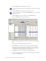
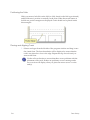
8. Exit Syntera.
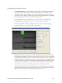
9. In Maxsys/MX Series Production, select the All Jobs tab. The job is listed
under the Pooled tab.
10. To move the job from the Pooled tab to the My Work tab:
A. Select the Pooled tab.
B. Select the job you want to accept.
C. Click Accept on the toolbar. The job moves to the My Work folder.
11. To complete the loading process, select the job under My Work and click the
Load icon on the toolbar. Alternately, you can click Start on the upper status
bar, which will load the job as it begins to run it.
You can load only one Syntera job at a time. If you select more than one job,
the Load button is disabled.
As the job(s) finishes loading, the job status changes from Ready to Loading
to Loaded.
Refer to "Running Syntera Jobs" on page 36 for information about running
loaded jobs.
32
Production
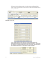
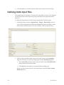
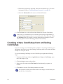
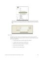
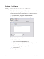
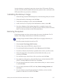
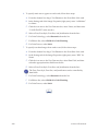
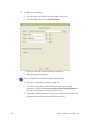
Loading CardSystem Manager (CSM) Jobs
Perform one of the following procedures to load CardSystem Manager (CSM) job
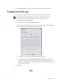
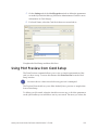
files into the system from the CSM tab on the Load dialog box. You can use the
standard method or QuickConnect.
Using the Standard Method
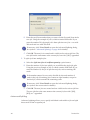
1. If necessary, define the CSM that will be used.
A. In Diagnostics (Applications | Utilities | Diagnostics), select Controller
from the module list.
B. Under the Controller Configuration Editor tab, double-click System from
the list to expand it and then expand CSM Client.
C. Under CSM Client, select Enable and then set the value to "true" on the
top bar by double-clicking the "false" value and selecting the option
button in the pop-up box.
D. Under CSM Client, select Server Name and then set the value to the
server name that you will be using.
E. Similarly set the values for Server User Name and Server User Password,
if necessary.
F. Click Commit to save the changes.
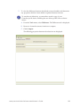
2. In the Production window (Applications | Production), click the Load button
on the upper status bar.
Maxsys and MX Series Software Administrator’s Guide
33
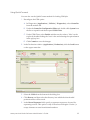
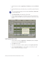
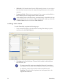
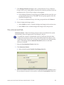
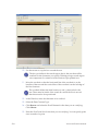
3. Select the CSM tab at the bottom of the dialog box.
4. Click Connect to CSM. The program connects to the CSM defined previously
and displays the first available job in the Selected CSM text box. The size of
the job appears in the File Size text box.
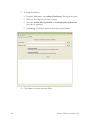
5. For Job Setup, click Browse to display the Job Setup Selection dialog box.
Select the setup you want to use, and then click Open.
6. Click Load Current Job to load the job displayed in the Job Name text box. To
load all jobs contained in the CSM, click Load All Jobs. The loaded job(s)
appears in the Ready Jobs/All Jobs lists.
If you are loading a large file, the program allows you to run CSM
jobs while the job is still loading.
You can also select the Use Selection Criteria check box to let the program
search through existing Job Setups (that contain selection criteria) to find a
name that matches the job file.
Refer to "Running Maxsys/MX Series Jobs" on page 36 to run loaded jobs.
34
Production
Using QuickConnect
You can also use the QuickConnect method for loading CSM jobs.
1. Reconfigure the CSM option.
A. In Diagnostics (Applications | Utilities | Diagnostics), select Controller
from the module list.
B. Under the Controller Configuration Editor tab, double-click System from
the list to expand it and then expand CSM Client.
C. Under CSM Client, select Enable and then set the value to "false" on the
top bar by double-clicking the "true" value and selecting the option button
in the pop-up box.
D. Click Commit to save the changes.
2. In the Production window (Applications | Production), click the Load button
on the upper status bar.
3. Select the CSM tab at the bottom of the dialog box.
4. Click Browse and then select the directory into which the downloaded
production files will be saved.
5. In the Record Separator field, specify a separator sequence to be used for
separating records. This option is only for fixed record lengths. Use the \x
escape character to enter hexadecimal numbers.
Maxsys and MX Series Software Administrator’s Guide
35
6. Click Download to load a job file to the directory specified in step 4.
The Files field contains a list of previously downloaded files that
reside in the directory. You can select and delete files from the list.
7. To load the job into the database:
A. Browse to the downloaded job and select a Job ID.
B. Select the Maxsys/MX6000 tab at the bottom of the dialog and then click
Load. The job appears in the Ready Jobs and All Jobs lists.
Refer to "Running Maxsys/MX Series Jobs" on page 36 to run loaded jobs.
Running Jobs
After loading one or more jobs from Maxsys/MX Series, Syntera, or CSM, use one
of the following procedures to run the job(s).
Running Maxsys/MX Series Jobs
1. In the Maxsys/MX Series Production window (Applications | Production)
under the Ready Jobs tab, select a job from the Ready Jobs list. You can select
multiple files that run contiguously.
2. Select the job type (Cards Only, Forms Only, Cards and Forms) from the list.
3. Click Start.
If a job has any rejected cards or has cards that were previously held and are
now not held, select that job and then click Remake to re-run the job.
Running Syntera Jobs
1. Select Applications | Production.
36
Production
2. Select the All Jobs tab in the left pane of the screen.
Use the Search facility at the bottom of the left pane to find jobs of particular
interest.
3. Select the Pooled tab in the right pane and then select a job.
When a job is selected, you can click the View Details icon to see the specific
products in the job.
4. Click the Accept icon to move the job into your My Work folder.
5. Select the My Work tab and then select the job.
6. Review the Operator Instructions and Notes near the bottom of the right
pane.
7. If necessary, select a different Job Setup from the list.
8. If the Allocate icon is available, click it to allocate materials for the job.
9. From the list above the left pane, select whether you want to print the
Card&Form, Form Only, Card Only, or UltraForm for this job. This field
overrides the information defined in the job specification.
10. Click Start (arrow icon) on the left side of the upper status bar.
11. While cards are being personalized, you can monitor progress of the job by
selecting the Production tab.
Maxsys and MX Series Software Administrator’s Guide
37
12. When the job is complete, click Release on the toolbar.
A. (Optional) Click in the bottom of the dialog box and type instructions to
the next operator in the process.
B. Click Release.
13. Click Refresh to remove the job from your My Work tab.
“User Input Needed” Message
After starting a job, one or more “User Input Needed” dialog boxes may appear
that prompt you to take some action to ensure that the job completes successfully.
Until the action is done, the dialog box continues to appear.
•
The messages state the problem and the module in which the problem is
occurring. Once you have completed the necessary tasks, click OK.
•
Some of these messages may be overridden. For example, a job may call for a
blue ribbon, but the system detects that a black ribbon is loaded. If you wish
to use the black ribbon for this production run only, select the Override check
box.
Viewing Jobs
When a job is running, perform the following steps in the Production Station to
view information about that job.
1. In the Production Station (Applications | Production), select the All Jobs tab.
(On the Syntera interface, also select the My Work tab.)
2. Select the running job.
3. Do one of the following:
•
Click View Details on the bar above the list.
•
Select the Job Details tab.
4. From the Production Tab, select the check box next to the message types
(Error, Caution, Information) that you want to view in the message pane.
5. Double-click a status message to view details about that message.
There may be a delay between the time you select a function button and the
time when the system is ready for another input.
38
Production
Viewing Cards/Forms
Perform the following steps to view cards or forms within a job on a Maxsys/MX
Series Production interface.
1. In the Production window (Applications | Production), select the Job Details
tab. The Job Details screen contains a list of all cards in a selected job.
2. Select a card/form from the list.
3. Click View Accounts on the bar above the list to display information related
to the card/form that you selected.
The record must contain card/form data to display. Multiple cards/forms can
be selected and results are listed in color-coded groups.
Print Preview from Job Details
Print preview from the Job Details tab allows you to proof a card after it has been
produced. The preview shows printable graphics information such as image, text,
and barcode elements. You can view non-printable information such as magstripe
and smart card data in the Job Details table. For more information, refer to
Chapter 6: “Using Print Preview from Card Setup” on page 123.
Perform the following procedure to access Print Preview from Job Details.
1. In the Job Details table, select a single row or multiple rows. If multiple rows
are selected, the cards will be displayed in the order of their record number.
Maxsys and MX Series Software Administrator’s Guide
39
2. Open the print preview dialog.
•
Right-click on the selected records and then click Print Preview.
or
•
Click the Print Preview button.
If more than one record was selected in the table to preview, the row will
be highlighted in light blue to correspond with the record currently
being previewed in the Print Preview dialog.
If the Card Setup is changed after loading the job or running the job, the
preview will not necessarily match the printed card.
40
Production
The following table describes the dialog properties on the Front, Back, and Both
Sides tabs.
Front/Back/Both Sides Tabs Properties
The “Virtual Card”
The representation of the card as designed using Card
Setup. Only Image, Text, and Barcode elements will display.
Zoom
Select the zoom level to view greater or less detail
Rotation
Rotates the card clockwise in increments of 90 degrees
Show Background
Select the check box to display the background image (if
any). The background image is associated with the
selected card stock as defined in Stock Management.
Auto Refresh
Select the checkbox to allow the preview image to refresh
automatically when any change occurs to the Image, Text,
or Barcode elements. A decrease in performance may
occur if many changes are being made.
Refresh
Click to refresh the preview image
Product Record
Use the navigation buttons to scroll through product
records. The single arrow button (>) will increment or
decrement by one, the double arrow button (>>) will
increment or decrement by 10, and the final button (>|)will
jump to the beginning or end of the record list.
Product records are used only when the Product Record
option button has been selected in the Preview Data tab.
The record will then be taken from the selected job.
Slide Show
•
Click the forward or reverse buttons to scroll through the
product records. Click the stop button to stop the slide
show.
Click OK when finished.
Maxsys and MX Series Software Administrator’s Guide
41
Remaking Jobs
If a job requires a remake, perform one of the following procedures.
Remaking a Maxsys/MX Series Job
Use the following procedure to remake cards that were rejected.
1. In the Production window (Applications | Production) under the All Jobs
tab, select the job from the list.
2. Select the Job Details tab. The Job Details screen contains a list of all cards in a
selected job.
3. If any cards have been rejected, click Remake in the upper bar to remake
those cards.
You can click and drag using your mouse and use Alt+Click or Shift+Click
to select multiple cards.
4. Click Refresh to update the screen manually.
Remaking a Syntera Job
Perform the following steps when a job requires a quick or advanced remake.
1. In the Production window (Applications | Production), select the All Jobs
tab. Under the My Work tab, select the job that requires remakes.
2. Click View Details. The Job Details list is displayed.
3. In the left pane, select the filter for the type of product you want to remake.
For example, to remake cards, expand the Cards folder and click Reject.
4. Select the products you want to remake (or click Select All) and then click one
of the following buttons in the toolbar:
•
Quick
In the Quick Remake Wizard dialog box, click Start and then click OK.
The remake job displays under your My Work tab as
OriginalJobName.R1.
•
Advanced
Follow the prompts in the Advanced Remake Wizard dialog box. The
remake job displays under your My Work tab as OriginalJobName.R1.
42
Production
Stopping/Pausing/Cancelling Jobs
When a job is running, perform the following steps on the Production screen to
stop or pause the job.
1. In the Production window (Applications | Production), select the Production
tab. (On the Syntera interface, select any tab.)
2. Click Stop to stop the job. (To stop the job only temporarily, click Pause.)
The system attempts to finish any cards that are already in the track.
•
If the auto-remake function is enabled and an error is encountered, click
Stop (No Pick) to stop the job and prevent the system from initiating a
remake on the card that caused the error.
•
Click Remake to remake the rejected cards from the last job.
3. Once you are ready for the job to resume, click Resume/Start.
Clicking the Abort button will cancel the job and sweep the cards out of the
machine (clear the track). No remake or error recovery will occur.
Splitting Jobs
Splitting is the act of creating multiple jobs from the cards or forms contained
within a single job.
For example, if Job A contains 1000 cards, and you would like to split it into more
manageable-sized jobs, Production allows you to split the job in two at a specific
point (card/form) in the job, or into multiple jobs.
Splitting Maxsys/MX Series Jobs
1. In the Production window (Applications | Production) under the Ready
Jobs, All Jobs, or Job Details tab, click Split on the bar above the job list. The
Split dialog box displays the Job name and Job size.
2. To split one job into two jobs:
A. Select the Split before card/form # option button.
Maxsys and MX Series Software Administrator’s Guide
43
B. Enter the card/form number that you want to be the first card/form in the
new job. Using the example of Job A, which contains 1000 cards: If you
enter the number 301, the single job is then split into two jobs—one with
300 cards and one with 700 cards.
If necessary, click View Details to open the Advanced Splitting dialog
box (refer to "Advanced Splitting" on page 44 for details).
C. Click OK. The new job is created and is visible in the various job lists. The
new job has the same name as the current job, but with “[001]” appended.
3. To split a job into multiple jobs:
A. Select the Split into jobs of card/form quantity option button.
B. Enter the number of jobs into which you would like the single job split.
Using the previous example of Job A, which contains 1000 cards: If you
enter the number 10, the job is split into ten jobs, each containing 100
cards.
If the number entered is not evenly divisible by the total number of
cards in the job, all resulting jobs contain an equal number, except for
the final job, which contains the remaining cards.
If necessary, click View Details to open the Advanced Splitting dialog
box (refer to the next section for details).
C. Click OK. The new jobs are created and are visible in the various job lists.
The new jobs have the same name as the current job, but with “[001],
[002], etc.” appended.
Advanced Splitting
Advanced splitting allows you to specify individual cards within a job and split
these cards off into a separate job.
44
Production
1. In the Production window (Applications | Production), select the Job Details
tab.
2. On the Job Details screen, select the cards you would like to split off from the
job.
You can click and drag using your mouse and use Alt+Click or Shift+Click
to select multiple cards.
3. Click Advanced Split on the right side of the toolbar.
4. In the confirmation dialog box, verify that the cards you have selected are to
be split, and then click OK. The new job is created and is visible in the various
job lists.
Splitting Syntera Jobs
1. In the Production window (Applications | Production) under the All Jobs
tab, select a job from the My Work folder.
2. Click Split in the toolbar.
3. Enter the record number at which to split the job in the Split at card # field.
4. In the Account Split Option box, select whether you want the job to split
before or after the card number you entered.
Maxsys and MX Series Software Administrator’s Guide
45
5. Click OK. The Split Job dialog box opens, confirming at what record index
number the job split. The split job appears in the My Work folder as <Job
Name.S1>
Remake jobs cannot be split.
If a job is partially complete (that is, some of the products have a status other
than "none"), you can split only the unattempted cards into the new job.
If any unattempted cards are related to cards that have already been
attempted (that is, multi-card accounts), the related unattempted cards will
stay with the original job.
Searching for Jobs
Perform the following steps to search for jobs within the database:
1. In the Production window (Applications | Production), select the All Jobs
tab. (On the Syntera interface, also select the My Work tab.)
2. In the left pane, select the check box next to any or all of the parameters on the
jobs list that you would like to use in your search. The more you select, the
narrower the scope of the search.
46
•
Name - Enter the name of the job in the text box.
•
Status - Select the status from the list. The program displays only those
jobs with the selected status.
•
Total Cards - Total cards in the job. Enter a number in the text box and
then select a quantitative indicator (less than, more than, equal to, etc.)
from the list. For example, if you enter 500 in the text box and select the
greater-than-or-equal-to (>=) sign from the list, the program displays only
those jobs that have 500 or more cards.
•
Due Date (Syntera only) - Enter the date range to search within.
•
Created (not available on Syntera) - Enter a number in the text box and then
select Hours or Days from the list. For example, if you enter "5" in the text
box and select "Days" from the list, the program displays only those jobs
created in the past five days.
•
Last Worked On (not available on Syntera) - Enter a number in the text box
and then select Hours or Days from the list. For example, if you enter "8"
in the text box and select "Hours" from the list, the program displays only
those jobs worked on during the past eight hours.
•
Job Setup (not available on Syntera) - Select Browse, and then select a Job
Setup from the dialog box. The program displays only those jobs that use
the selected Job Setup.
Production
•
Input File (not available on Syntera) - Enter the Input File name into the text
box. The program displays only those jobs that use the listed Input File.
•
Has Rejected Products - If selected, the program displays only jobs that
contain rejected products.
•
Has Held Products - If selected, the program displays only jobs that
contain held products.
•
Machine Setup (Syntera only) - Select a machine setup value from the list.
3. Click Search to initiate the process. The top area of the left pane changes to
reflect your search.
Click Clear to clear all parameters and display all jobs in the list.
Holding/Removing Products from a Job
Perform one of the following procedures to hold, reject, or remove a product from
a job.
Holding/Rejecting Cards from a Maxsys/MX Series Job
1. In the Production window (Applications | Production) under the All Jobs
tab, select a job from the list.
2. Select the Job Details tab. The Job Details screen contains a list of all cards in
the selected job.
3. To reject a card or cards from the job:
A. Select a card or cards from the list.
B. Click Set Reject on the upper bar to reject the card manually. (The card
must first have been processed successfully in order to be rejected
manually.)
C. To override the “Reject” status, select any rejected cards from the list, and
then click Set Good.
4. To hold a card or cards from being processed when the job runs:
A. Select a card or cards from the list.
B. Click Hold on the upper bar.
To release the hold, select any cards with a "Hold" status from the list, and
then click Release Hold.
Maxsys and MX Series Software Administrator’s Guide
47
Holding/Removing Products from a Syntera Job
1. In the Production window (Applications | Production), select the All Jobs
tab.
2. Under the My Work tab, select the original job that contains the product of
interest.
3. Under the Job Details tab, select the products you want to process and click
Special.
4. If you are not already logged in as an administrator, the Login window
displays. Enter your Admin User Name and Password in the fields provided
and click OK.
5. Select the appropriate special processing request option(s):
•
Pull - Removes the selected product(s) from the current job, but not from
the Syntera system. Products in the "Pulled" state cannot be added to a
job. You must first restore the product and reset the state to "Available"
before jobbing.
•
Remove - Removes the selected product(s) from the current job and
makes it available for jobbing. If you want to hold the products in your
My Work folder (making them unavailable for jobbing), select Hold. Clear
the Hold check box to return the items to the pool.
•
Expedite - Splits off records from a job as a new job. If you select this
option, select the appropriate Process and starting Process Step from the
lists and, if necessary, change the Due Date to accelerate the priority of the
job.
6. Click OK.
Deleting Jobs
For Maxsys/MX Series production jobs, perform the following steps to delete a
job permanently from the database.
1. In the Production window (Applications | Production), select the All Jobs
tab.
2. Select a job or jobs from the list, and then click Delete Job on the upper bar to
remove the job(s) permanently from the database.
You cannot select non-consecutive multiple jobs (using Ctrl+Click).
When a job is deleted, so is the Audit Report backup.
Deleting a job cannot be undone.
48
Production
3. Click Restore Audit on the upper bar to restore an audit file from the
database in the event it has been deleted or corrupted.
Allocating Materials in Syntera Production
On a Syntera-enabled station, use the following procedure to assign allocated
materials from the vault to a job.
1. In the Production window (Applications | Production), select the All Jobs
tab.
2. Click the My Work tab in the right pane and then select a job.
3. Click the Allocate icon on the toolbar.
4. From the list, select the appropriate Card stock needed.
5. Select one or more items from the list at the top of the window and do one of
the following:
•
Click Allocate All to allocate the exact quantity of the selected card stock
for the item(s) selected.
•
Click Allocate to enter an overage of stock. Enter the overage quantity in
the Input field and click OK.
6. The Allocated card stocks list displays information about what materials
have been allocated. Select an item from this list and do one of the following:
Maxsys and MX Series Software Administrator’s Guide
49
•
Click Remove to free the allocated materials.
•
Click Edit Status to change information about the material. (Enter the
required information in the administrator login dialog box.) To change the
number of unused materials manually, enter a number in the Un-used
field. To manually change the number of rejected materials, enter a
number in the Reject field. Click OK.
•
Click Transfer Overage to transfer unused stock to a job that requires it.
Select a job from the job list, type the quantity to be transferred, and click
OK.
7. Click Close.
Performing Syntera Administrative Functions
To perform Syntera administrative functions for a job, complete the following
steps:
1. In the Production window (Applications | Production), select the All Jobs
tab.
2. Click the My Work tab in the right pane and then select the job for which you
want to perform administrative functions.
3. Click Admin on the toolbar. If you are not logged in as an administrator, a
login window opens. Enter your Admin User Name and Password in the
fields provided and click OK.
4. If you clicked Start and the file does not transfer from Syntera, select Regenerate to have Syntera re-transmit the file.
5. To remove all products from the job and delete the job, click Cancel.
6. In Manual Reconciliation Mode, you can override the current job state. To
enter the mode, click Manual Reconciliation Mode and then, in the Start
Index field, enter the card index number where the machine should begin
tracking (the record number of the last good card plus 1).
The Start Index function is used in situations such as when the machine is
accidentally powered off during production, resulting in the system
incorrectly reporting the number of cards complete, in process, etc.
7. Click OK.
50
•
If you selected Re-generate, the system displays a confirmation message.
•
If you selected Cancel, the system returns the job to Available Work so it
can be rescheduled through Basic Job Creation or Advanced Job Creation.
Production
•
If you selected Manual Reconciliation Mode, the Set Good and Set None
buttons in the Job Details section of the Production window are available.
Select a product and click Set Good to change the status to Good. Select a
product and click Set None to change the status to None.
When you are finished using the Manual Reconciliation Mode functions,
turn it off by clicking Admin again and clearing the Manual Reconciliation
Mode check box.
Adding Notes in Syntera Production
Syntera allows you to add notes that convey special instructions or messages to
operators or other personnel about production.
Adding Operator Instructions or Job Notes
To add operator instructions or job notes for a job, complete these steps:
1. In the Production window (Applications | Production) on one of the Job
screens, select a job from the list and then click the Job Notes icon.
2. Click Add Note.
3. (Optional) Select a reason code from the list.
4. In the New Notes text box, enter the note text.
5. (Optional) To have the job note copied to the station, click Apply New Notes
to Station Notes.
6. Click Apply.
The date/time the note was created, as well as the user name of the person
who entered it, are inserted before the note text.
Notes are listed in chronological order with the newest note at the bottom.
Adding Station Notes
To add station notes that are unrelated to jobs, complete these steps:
1. In the Production window (Applications | Production) on one of the Job
screens, select a job from the list and then click Station Notes.
2. Click Add Note.
3. (Optional) Select a reason code from the list.
4. In the New Notes text box, enter the note text.
5. (Optional) To have the station note copied to the currently-selected job, click
Apply New Notes to Job Notes.
Maxsys and MX Series Software Administrator’s Guide
51
6. Click Apply.
The date/time the note was created, as well as the user name of the person
who entered it, are inserted before the note text.
Notes are listed in reverse chronological order with the newest note at the
top.
52
Production
Chapter 3: The Event Log
This chapter provides information on querying and viewing
system events using the Event Log.
The Event Log allows you to query and view system events. System events are
logged automatically as the system and software program operate. These events
can be viewed and analyzed for system administration and troubleshooting
purposes. Events returned by the query are displayed in tabbed lists that can be
saved for later viewing or for archiving.
Privileges for this utility may be defined when security is enabled; refer to
Chapter 14: “Security Configuration” on page 203.
Events and activities captured in the event log include but are not limited to:
•
Starting Administrator or production operator user interface tools
•
Opening, creating, saving, deleting, or closing a setup
•
Production data file loading, creating production job(s) in the DB2 database
•
Production job run attempts and all events that are generated in the context of
the production run
•
Production job deletes
Querying the Event Log
Perform the following procedure to query the Event Log.
1. Select Applications | Event Log.
2. In the Event Log tool bar, click Query Event Log.
Maxsys and MX Series Software Administrator’s Guide
53
3. On the Time Range tab (displayed by default), select the time range for your
query.
•
Select All Events to include all system events since the inception of the
system (time will not be considered).
•
Select Last and then make a selection from the list (i.e., 30 days) to include
only those events in the selected period of time.
•
Select Time Range to enable the calendar. Using the calendar, you can
specify the date and time range (down to the second). Use the arrow
buttons to navigate through the month and year, click a date in the
calendar, and then use the spin controls to designate the time of day.
4. On the Query Filters tab, select the type of events you want the query to
return.
54
The Event Log
•
Select Restrict to user commented entries to return only events that have
user comments included.
•
From the Include messages of severity list, select from the following list:
•
•
Alert - A event that may have required user intervention or that may
have lead to an error
•
Error - An event that may have caused the system to cease normal
operation
•
Warning - An event that, if not addressed, may have impacted the
functionality of the system
•
Info - System events that required no action (information only)
•
Diagnostic - Information returned by a diagnostic test or function
From the Include messages of type list, select those event message types
that correspond to your informational needs. You can select multiple
message types using Ctrl+Click or Shift+Click.
When query filtering is performed a notification appears in the
lower-left corner of the window.
Maxsys and MX Series Software Administrator’s Guide
55
5. On the Column Filters tab, select the Columns of query data to include in the
query. The events can be filtered as follows:
56
Visible
Indicates whether the selected column is visible
Column
Column name
Filter
Enter text to filter the column. For example, if you want to
display only events with a severity of Error, you would type Error
into the field.
You can use wildcard characters to further define the filter. For
example, if you are filtering the Message parameter, entering
*event* will return all results that contain the word event in the
message.
Regex
Select this option to filter using Regular Expressions
Ignore Case
If selected, word case is ignored
OR
Takes the filter values (space separated) and will display any
value that matches. For example, if you are filtering the
Message parameter and enter *query* *application*, then all
messages that contain the words query or application will
display.
NOT
Takes the filter value(s) (space separated) and will display any
value that does not match. For example, if you are filtering the
Message parameter and enter *query* *application*, then all
messages that do not contain the words query or application
will display.
The Event Log
6. When the time, filters and column parameters have been selected for your
query click OK to perform the query. The results are displayed on a tab in the
event log viewer window.
7. Multiple queries may be performed and are displayed (by query date range)
as individual tabs in the program window. To start a new query click Query
Event Log from the tool bar.
Event Viewing Options
Filters can be applied to an open query so that specific events can be located
quickly.
1. With the Event log Viewer active, select the query to filter by clicking on the
tab.
2. Click Edit to open the Query Event Log dialog.
3. Use the time range, query filters and column filters to modify the query
parameters.
4. Click Ok to view modified query results.
Maxsys and MX Series Software Administrator’s Guide
57
Viewing Message Details
To view the details of an event message, double-click the event in the list. You can
browse through the messages by clicking the arrow buttons at the bottom of the
Message Details window. The single arrow buttons will take you to the previous
or next message in the list. The double arrow buttons will open either the first or
last message in the list.
The Extended Help tab contains error message information and the Details tab
gives detailed information about the event.
Click OK to close the window.
Adding Comments to Messages
You can add user comments to message details by clicking Comments and then
entering the comments into the Update User Comments dialog.
Searching the Event List
The Event Log allows you to perform a search for keywords in the returned event
list. Perform the following procedure to perform a search.
1. From the Event Log Edit menu, select Find or press Ctrl+F on the keyboard.
2. Type a keyword into the Find text box.
3. For Find Options:
•
Regex - Select this option to search using Regular Expressions. If you
select this option, the following two options are not available.
•
Ignore Case - The search will not consider whether upper or lowercase
letters in the found word match the word you entered.
•
Whole Words - The search will consider only the entire word you entered.
For example, if you entered “no” and you do not select this option, the
search will locate the letters “no” within other words (such as “not”).
4. Click Next to begin the search. Any matching words will be highlighted.
Continue clicking Next to find each subsequent instance of the word. Click
Previous to go back to the previously highlighted instance.
Sorting Returned Events
The Event Log allows you to sort the returned events in the list by date/time.
Perform the following procedure to sort the events.
1. From the Event Log Tools menu, select Event Log Preferences.
58
The Event Log
2. From the Sort Order tab, select either Ascending or Descending and then
click Apply. The list is sorted chronologically by date/time in the manner
selected.
To update the events list, click Refresh.
Exporting Events
You can export events for use in archiving or troubleshooting. Perform the
following procedure to delete the event log from the system.
1. Select Applications | Event Log.
2. From the menu select Tools | Export Events. The Export dialog opens.
3. Select the appropriate options.
•
Select Include Events to include all displayed or highlighted events in the
export file. If you want to export selected events in the list, you can run the
display filter or select individual events using Ctrl/Alt+Click.
•
Select Include Trace to export a trace file. Trace files are used by Datacard
for diagnostic purposes.
When the Include Trace file is selected, the Include Personalization Data
option is enabled. This option is a potential data security risk and should
be used with caution as it would enable data from the production run
including account numbers, card holder names, addresses, etc. to be
included in the extracted trace file.
•
Select Zip Results to compress the file(s) into one “.zip” file.
4. Select the destination directory. Datacard recommends using the default
directory.
Maxsys and MX Series Software Administrator’s Guide
59
5. Click Export to File. The file(s) will be exported to the defined location.
Purging the Event Log
Perform the following procedure to delete the event log from the system.
All event tabs must be closed before a deletion is allowed. If the Event
Log is open, close it before beginning the following procedure.
1. Select Applications | Event Log.
2. From the menu select Tools | Purge Events.
3. The Purge Events window will open. You can purge either all events from the
log or events that occurred before a particular date.
A. To purge all events select the All Events option button.
B. To purge by date select the Events Before this Date option button. Use
the arrow buttons to select the month and year, and then click on the
calendar to select the date. Use the spin controls or enter values in the text
boxes to define the time.
4. Click OK.
60
The Event Log
Chapter 4: Job Setup
This chapter provides information on creating and modifying Job
Setups.
Creating a New Job Setup
Job Setups combine the various required and optional setups to form a job that
can be loaded and run on the card issuance system. Job Setups require a Data
Setup, Card Setup, and Production Options Setup and are generally created after
all other setups have been defined. Depending upon your job, the Audit Setup,
Backup Location and Form Setup are optional setups that may be used. Complete
the following steps to create a new Job Setup.
There can be only one Job Setup open at a time. Make sure that you save the
new setup before opening another.
1. Select Applications | Setups | Job Setup.
2. In the Job Setup window, click New on the toolbar.
Maxsys and MX Series Software Administrator’s Guide
61
The Settings Tab
The Settings tab allows you to select and define settings for the Job Setup.
1. Under the Settings tab, use one of the following methods to select a Card
Setup to use for this job.
•
Click Browse and then navigate to the file's location.
•
Click the icon to select Data Field information for this operation.
•
Select the Use Selection Criteria check box to let the program search
through existing Job Setups to find the file name that matches this Job
Setup. Click Open to view the selected Setup.
2. Choose a Form Setup (if required) by clicking Browse and then navigating to
the file's location or click the icon to select Data Field information for this
operation. Click Open to view the selected Setup. Click Clear to clear the
selection.
3. Choose a Data Setup by clicking Browse and then navigating to the file's
location. The Data Setup list is available only if Use Selection Criteria is
selected in the Card Setup section above. If Selection Criteria are not used,
then the Data Setup is defined by the selected Card Setup. Click Open to view
the selected Data Setup.
4. Choose a Production Options Setup by clicking Browse and then navigating
to the file's location. Click Open to view the selected Setup.
5. (Optional) Choose an Audit Setup by clicking Browse and then navigating to
the file's location. Click Open to view the selected Setup. Click Clear to clear
the selection.
6. Click Browse next to the Backup Location text box. The Open dialog box is
displayed. Browse to the location where you want to store data, and then click
Open. Click Clear to clear the selection.
You must choose a backup location or the data will not be archived.
7. If required, select the Use Read Lookup check box to enable read lookup
functionality. You must have a Magnetic Stripe Read or Smart Card operation
in the Card Setup before Read Lookup can be configured. Read Lookup is
used to verify pre-programmed smart card chips at runtime. A lookup field
(i.e. account number, name, etc.) must exactly match an indexed data field for
the personalization process to continue. The Allow Duplicates check box can
be selected if this option is desired.
Read lookup is mutually exclusive with Card Setup selection criteria.
62
Job Setup
8. Select a Smart Card Operation, Lookup Field, and Match Data Field from
their respective lists.
9. Click the Save icon on the toolbar to save the new Job Setup.
The Selection Criteria Tab
The Selection Criteria tab allows you to select whether selection criteria are used.
The new Job Setup will be used when specific criteria are met.
To enable the system to automatically select a Job Setup based on selection
criteria when the data loads, the criteria defined must be unique to the Job
Setup. If the criteria are not unique, the system will not automatically select
the Job Setup and the system will not successfully load the Job.
To use Selection Criteria perform the following steps.
1. Select the Use Selection Criteria check box.
2. Select a field from the Use this Job Setup When list.
3. Enter a user-defined value in the is like text box. If the value is case sensitive,
select the Case Sensitive check box.
For example, if you select the field ‘_DCG_FILENAME’ and enter the value
‘123ABC’ in the text box, when the system encounters the DCG file named
‘123ABC’, then the Job Setup will be used.
Note: You can use wildcard values when entering text. Use “*” to include
multiple characters in the search, or use “?” to include one character (for
example *_Name).
0
Note: No Selection Criteria associated with the new Job Setup are saved
when you use the Save As function.
4. Click the Save icon on the toolbar.
Maxsys and MX6000 Software Administrator’s Guide
63
64
Job Setup
Chapter 5: Data Setup
This chapter provides information on creating and modifying Data
Setups.
Creating a New Data Setup
Data Setups tell the system how to interpret the input data. Specifically, the Data
Setup provides the order of the input data fields and the code or position that
identifies the beginning and end of each data field. The system uses this
information to parse the Data Setup into the format used for production.
There can be only one Data Setup open at a time. Make sure to save the new
setup before opening another.
The Keyboard Entry utility allows job creation without an input data file.
Sample data can be entered manually using the keyboard or by file reference
in order to create a job. Manually created jobs may be reviewed prior to
production. For more information, refer to page 211.
Perform the following steps to create a new Data Setup:
1. In the Data Setup window (Applications | Setups | Data Setup), click the
New icon on the toolbar.
2. Complete the fields under the General tab to define the input file. (For
detailed information, refer to “Defining Data Input Files” on page 66.)
The elements on the General tab define for the system what the input data
stream consists of and how it behaves. This determines how the system will
interpret the input data stream it receives.
3. Complete the fields under the Data Fields tab to add data fields. (For detailed
information, refer to “Adding Fields” on page 67.)
The Data Fields tab defines the format of the individual data fields. This
information determines how the system will process individual fields within
the input data stream.
When adding fields, remember that by default the fields in the Data Setup
are set up in the same order of occurrence as in the actual input file, unless
you clear the Fields in Order check box under the Data Fields tab.
Maxsys and MX Series Software Administrator’s Guide
65
4. Click the Save icon on the toolbar to name and save the new Data Setup.
Defining Data Input Files
The system must be told how to interpret the input data it receives. The elements
on the General tab of the Data Setup component define the input data and its
behavior.
To define the input data for a Data Setup, complete the following steps:
1. In the Data Setup window (Applications | Setups | Data Setup), create or
open a Data Setup and then under the General tab, type a description of the
data stream in the Description box (for example, "ABC Company Data").
2. Under Product and Encoding, select your product type from the Product
Type list and then your data encoding type from the Encoding Type list.
•
Select Card Only if data contains only card data. Select Card and Form if
data contains card and form data.
•
Click About for information on selecting the encoding type.
If there are line location blocks in the data stream, select the Line Location
Blocks check box.
66
Data Setup
3. If you selected the Card and Form product type in step 2, define the form
information.
Before adding form information, you must first create a data field
specifically for forms.
Type - The number of cards that the form will contain is contained in the Data
Field information as created on the Data Fields tab (see below). The fields can
be one of the following types:
•
Cards Per Form Field
•
Basic Forms Data Field
Data Field - Based on the type selected, the available data fields will populate
the list.
Data Field Location - Select the form data field location (first or last record of
the account) from the list to specify the location of the form data field within
the data stream.
4. If the data stream uses FIRs, select the File Identification Record check box.
FIRs identify the start of a new logical file in the data stream and provide job
processing information to the system operator. If you use FIRs, a data stream
with two logical files (jobs) would look like this:
FIR Bank A Job FIR Bank B Job Stop FIRs
A. Enter the FIR identifier into the Identifier text box.
B. Select the number of Stop FIRs used from the list. This number must
correspond to the actual number of stop FIRs in the data.
5. Choose the Record Separation method.
•
Fixed Length - The number of bytes per record
•
Character Sequence - The actual unique characters that separate each
record, such as \x0D\x0A
6. Click the Save icon in the toolbar.
Adding Fields
A data field definition can be one of these types:
•
Data fields - Fields that tell the system how to process individual fields
within the input file
•
Constant fields - Static data fields
Maxsys and MX Series Software Administrator’s Guide
67
•
FIR fields - File Identification Records (FIR) identify the start of a new logical
file in the data stream and provide job processing information to the system
operator.
•
Composite fields - Fields that are comprised of two or more existing fields or
that combine parts of existing fields to make a new field.
When adding fields to the Data Setup, remember that by default the fields are
set up in their order of occurrence in the actual input file unless you clear the
Fields in Order check box under the Data Fields tab.
Adding Data Fields
To add a Data field, complete the following steps.
1. Create a new Data Setup or double-click an existing Data Setup to open it,
and then select the Data Fields tab.
2. Click New in the Data Field area. The new field is added to the field list as
DATAFIELD1, etc.
68
•
To insert a new field, select an existing field from the list and then
click Insert. The new field will be added above the one you selected.
•
To duplicate a field, select a field from the list and then click
Duplicate. The field will be duplicated and will appear below the
original field in the list.
Data Setup
3. Double-click on the new field name and then change the name if needed. Do
not use spaces in the field name.
4. Specify a Field Type.
•
String - Data presented as alphanumeric characters (trailing space
characters will be truncated, trailing null characters will remain)
•
Binary - Data formatted in binary (trailing space characters will be
preserved)
•
DCC Image - Data formatted in Datacard color image format (also called
DPCF)
•
UGL Data - This is data formatted in UltraGrafix Language (UGL) format
•
BasicForm - Data formatted for BasicForm Inserter
•
File Reference - Data retrieved from a referenced file
5. From the Unit list, select the data’s unit of measurement. The system will
optimize its performance based on the input unit.
6. Select and specify an Encoding Type in the Field Detail area, if needed.
7. If necessary, select one or more of the following Attribute options:
•
Secure indicates this field will be excluded from the Data Browser view of
the data.
•
Indexed indicates this field will be indexed (this attribute option is
required for read lookup production)
•
Required indicates this field must exist in each record for data to load
correctly.
•
Delete Referenced File indicates that if, within the string type field, data is
being pulled from a file, that file will be deleted upon completion of the
job to save disk space.
8. Specify the Start Identifier parameters:
•
String indicates exact text denoting information that belongs in this field.
From the Start of Field list, select String. In the String text box, type the
exact text that indicates the start of data for this field.
•
After Previous indicates that the information for this field comes
immediately after the information included in the previous field if the list
is complete. From the Start of Field list, select After Previous.
•
Record Position indicates this field will use data from a specific and set
location within the data stream. From the Start of Field list, select Record
Maxsys and MX Series Software Administrator’s Guide
69
Position. In the Record Position text box, type a number indicating the
exact position of the start of the data for this field.
9. Specify the End Identifier parameters, including:
•
Before Next
•
String - indicates exact text denoting the end of information that belongs
in this field. Type the exact text that indicates the end of data for this field.
•
Fixed Length
•
Embedded Length
•
UGL Data
10. (Optional) Enter a value in the Sample Value text box to display on the
sample page. This is done to preview the data and ensure proper placement/
appearance.
11. Click the Save icon in the toolbar to save the new stream field.
Adding Constant Fields
Use the following procedure to add a constant field of static data.
Constant fields used to specify X/Y positions or size values will be
interpreted by the program as being in thousandths of an inch.
70
Data Setup
1. Create a new, or double-click an existing Data Setup to open it, and then select
the Constant Fields tab.
2. Click New. The new field is added to the field list as CONSTANT1, etc.
•
To insert a new field, select an existing field from the list and then
click Insert. The new field will be added above the one you selected.
•
To duplicate a field, select a field from the list and then click
Duplicate. The field will be duplicated and will appear below the
original field in the list.
3. Double-click on the new field name and then change the name if needed. Do
not use spaces in the field name.
4. Enter a Field Value in the text box.
Adding FIR Fields
Use the following procedure to add FIR fields to the Data Setup.
FIR fields used to specify X/Y positions or size values will be interpreted by
the program as being in thousandths of an inch.
On Maxsys/MX Series Systems, a File Identification Record (FIR) cannot
exceed 1 megabyte (1MB).
Maxsys and MX Series Software Administrator’s Guide
71
1. Create a new, or double-click an existing Data Setup to open it and then select
the FIR Fields tab.
2. Click New. The new field is added to the field list as FIR1, etc.
•
To insert a new field, select an existing field from the list and then
click Insert. The new field will be added above the one you selected.
•
To duplicate a field, select a field from the list and then click
Duplicate. The field will be duplicated and will appear below the
original field in the list.
3. Double-click on the new field name and then change the name if needed. Do
not use spaces in the field name.
4. Enter a Sample Value in the text box.
Adding Composite Fields
Composite fields modify the data contained in a record's data fields and operate
on simple data fields or other composite fields to create new fields.
Constant fields used to specify X/Y positions or size values will be
interpreted by the program as being in thousandths of an inch.
Use the following steps to add a composite field.
72
Data Setup
1. Create a new Data Setup, or double-click an existing Data Setup to open it,
and then select the Data Fields tab.
2. Click New. The new field is added to the field list as COMPOSITE1, etc.
To insert a new field, select an existing field from the list and then click
Insert. The new field will be added above the one you selected. To duplicate
a field, select a field from the list and then click Duplicate. The field will be
duplicated and will appear below the original field in the list.
3. Double-click on the new field name and then change the name if needed.
The field name cannot begin with a number or contain spaces.
4. Select Secure to have the field be visible only to those with the View Secure
Data privilege.
•
Select Indexed to index the field for faster searching and to enable
searching from the Production details view (this attribute option is
required for read lookup production).
Maxsys and MX Series Software Administrator’s Guide
73
5. Select a Composite Field Result Property from the list and then specify the
parameters for the newly-created field as described in the table below.
Field Type
Description
Change Case
Changes the alphabetic case of a field.
Example: ThisIsATest is changed to THISISATEST.
To do this select a source field and then for behavior, select either to upper
or to lower (for upper or lowercase).
Change Field
Type
Used to change the field type of a data field or composite field function.
Used primarily to convert a String type field to a File Reference type field.
Example: Two string data fields, DIRECTORY and FILENAME are
concatenated, resulting in a composite field of field type string, which is
then converted using Change Field Type composite to a File Reference
that will specify an image location.
Concatenate
Appends a field with either a string of data or another field.
To do this select the Strings to Concatenate to Source Field.
Default for
Missing Field
Creates a new composite field whose value is that of a source data field
(if present) or a default value if the source data field is missing. This allows a
field to be defined which will always have a value, regardless of whether
or not the original data field exists in the product record.
Extract
BasicForm
Extracts BasicForm field (CPF or any of the other 99 lines) from the
CARDSPERFORM Data Field.
To do this select a source field and then for output, select either cards per
form or basic form line (with number selection).
Extract
Magstripe
Track
Extracts magnetic stripe track field for type of track used.
To do this select a source field and then a Track Type.
First Index
Before
Returns a numeric count of the number of characters from the first
specified characters to the beginning of the field.
Example: THISISATESTCARD 1, with a value of S returns a value of 3.
To do this select a source field and then either Character or Field.
First Index Of
Returns a numeric value of the position of the first character specified.
Example: THISISATESTCARD 1, with a value of S returns a value of 4.
To do this select a source field and then either Character or Field.
74
Data Setup
Field Type
Description
First Index
After
Returns a numeric value of the character following the first occurrence of
a specified character (from the beginning of the field).
Example: THISISATESTCARD 1, with a value of S returns a value of 5.
To do this select a source field and then either Character or Field.
Last Index
Before
Returns a numeric value of a count of the number of characters from the
last specified character to the beginning of the field.
Example: THISISATESTCARD 1, with a value of S returns a value of 9.
To do this select a source field and then either Character or Field.
Last Index Of
Returns a numeric value of the position of the last character specified.
Example: THISISATESTCARD 1, with a value of S returns a value of 10.
To do this select a source field and then either Character or Field.
Last Index
After
Returns a numeric value of the next occurrence of a specified character
from the beginning of the field.
Example: THISISATESTCARD 1, with a value of S returns a value of 11.
To do this select a source field and then either Character or Field.
Length Of
Returns the length of a particular field.
Example: THISISATESTCARD 1 returns a value of 17.
To do this select a source field.
Math
Create values which may be used in other functions, such as Substring
start and end indices. Two data sources and an operation (either addition
or subtraction) are selected. Each data source must supply data of type
‘String’, the data will be converted into an integer. The two resulting
integers will be added or subtracted according to the selected operation.
The output of the function is an integer value.
To do this select a source field (Data Field or Function), an operation (+ / -),
and an operand.
Maxsys and MX Series Software Administrator’s Guide
75
Field Type
Description
Pad
Pads the field with a specified character to a specified length.
Example: With a specified character 'S' and a specified length of 20
characters, THISISATESTCARD 1 (which contains 17 characters) becomes
THISISATESTCARD 1SSS to bring the field length to 20 characters.
To do this select a source field, select either Character or Field, and then
select either Integer or Field for field length.
Post Net
Converts a five-digit zip code to a Postnet Barcode
Example: 55343 becomes “!55343x!”
To do this select a source field.
Remove
Characters
Removes characters from a field. The removed characters can be defined
or can be another field.
To do this select a source field, select the characters to remove from either
String or Field, and then for behavior select the characters you want
removed (leading, trailing, both, or all).
Replace
Characters
Replaces character(s) in a field with other specified character(s).
Example: THISISATESTCARD 1, with old characters as 1 and new characters
as 2, returns a value of THISISATESTCARD 2.
To do this select a source field, select the old characters that you want to
replace (oldChars), and then select the new characters that you want to
use (newChars).
Substring
Used to further define a field by position (index).
Example: THISISATESTCARD 1, with a start index of 5 and an end index of 11
returns a value of ISATEST.
To do this select a source field, select either Index Value or Index Field for
the Start Index, and then select either Index Value or Index Field for the
End Index.
6. Click the Save icon in the toolbar to save the Data Setup.
Adding Display Fields
Display fields are up to five data fields (data fields, constant fields, or composite
fields) that display on the Production interface during a production run. This
enables the operator to see which record is being processed. Secure data fields are
not displayed.
76
Data Setup
Perform the following procedure to define and order Display fields.
1. Create a new Data Setup or open an existing Data Setup and then select the
Display Fields tab.
2. Select five fields from the list of available fields and then click the arrow
button (>).
3. Click the arrow buttons in the Selected Fields list to change the order of the
fields as they will appear on the production screen. Alternately, you can click
Sort to sort the fields in ascending or descending order.
4. Click Save. During production, the selected fields will display in the
production interface.
Maxsys and MX Series Software Administrator’s Guide
77
Changing the Order of Data Fields
It may be necessary to change the order of data fields if the fields in the Data
Setup were set up in the wrong order.
By default, the fields in the Data Setup are set up in their order of occurrence
in the actual input file, unless you cleared the Fields in Order check box in
the Data Fields tab.
Complete the following steps to change the order of fields within the Data Field
list.
1. Select the Data Fields tab.
2. Clear the Fields in Order check box.
3. Select a data field from the Data Field list.
4. Use the up and down arrows to move the selected data stream field up or
down the list. Repeat this process until all data stream fields are in the correct
order.
The double arrow button moves the field in increments of ten.
5. Click the Save icon in the toolbar to save the changes.
Deleting Data Setups
Complete the following steps to delete data setups.
1. In the left pane of the Data Setup window, highlight the Data Setup you want
to remove.
2. Click the Delete icon in the toolbar. A message box opens for confirming the
deletion.
3. Click Yes. The Data Setup is removed from the system.
78
Data Setup
Chapter 6: Card Setup
This chapter provides information on creating and modifying Card
Setups.
A Card Setup defines an individual card that has certain properties and contains
certain element sets (label, image, overlay, etc.). Each Card Setup can be used to
create multiple card products that each contain the defined properties and
elements. This application allows you to perform the following tasks.
•
Add elements (embossing,
graphics, smart card encoding,
etc.) to cards
•
Define selection criteria to enable
automatic selection of a Card
Setup when the data loads
•
Configure elements
•
Set up crosschecks
•
Add fields already defined in one
or more Data Setups
•
Save an existing Card Setup as a
new Card Setup
•
Preview the card using the Print
Preview command
Opening Existing Card Setups
To open an existing Card Setup, complete the following steps:
1. In the Card Setup window (Applications | Setups | Card Setup), click the
Open icon on the toolbar.
2. Select a Card Setup from the list.
3. Click Open.
There can be only one Card Setup open at a time.
Maxsys and MX Series Software Administrator’s Guide
79
Creating a New Card Setup
If you are creating a Card Setup that is similar to an existing Card Setup, it is
often faster and easier to save the existing Card Setup as a new setup and
modify it to suit your needs. Refer to "Creating a New Card Setup from an
Existing Card Setup" on page 82.
There can be only one Card Setup open at a time. Make sure that you save
the new setup before opening another.
To create a new Card Setup, complete the following steps:
1. Select Applications | Setups | Card Setup.
2. In the Card Setup window, click New on the toolbar. A new Card Setup form
opens that depicts a blank card setup with a virtual card on the left side and a
Properties view on the right.
80
Card Setup
3. Add elements to the Front (top view) or Back (bottom view) of the virtual
card. Drag an element from the element list (the columns of icons on the left
side of the window) to the card. Some elements can be placed directly on the
card, while others will go to the docking column on the right side of the card.
Those elements that are placed directly on the virtual card can be moved
to the approximate location of the finished product; since this is not a
true WYSIWYG interface, do not rely on the placement for card design.
Rather, the element properties' Settings tab contains fields where the X
and Y coordinates can be defined.
Your hardware configuration may not match all available elements.
Ensure that the modules on your system match the elements that you
will be using in the Card Setup.
4. Define the Card Properties as required. (For more information, refer to
“Defining Card Properties” on page 83.)
5. Set the properties for each element (if required).
•
Click the element icon on the virtual card, or click Element List and then
select an element. The Properties view for that element appears on the
right side of the window.
Maxsys and MX Series Software Administrator’s Guide
81
•
Define the properties as required, based on the element type. (For more
information, refer to "Defining Element Properties" on page 91.)
•
Select the Advanced tab for access to advanced features.
6. Click the Save icon on the toolbar when finished to save the Card Setup.
If the setup you created does not conform to basic design requirements, a
warning message appears and you are not allowed to save the setup. Click
the Warning button to display a window that lists the warnings or errors
that may prevent cards from being produced successfully.
Creating a New Card Setup from an Existing
Card Setup
If you are creating a new Card Setup that is similar to an existing Card Setup, it is
often faster and easier to save the existing Card Setup with a new name and then
modify it to suit your needs.
To save an existing Card Setup as a new Card Setup, complete the following
steps:
1. From the Card Setup window (Applications | Setups | Card Setup), open
the Card Setup to copy.
2. Click the Save As icon on the toolbar.
3. Enter a new file name in the File Name field and modify properties as
needed.
4. Click Save to save the Card Setup with the new name.
No Selection Criteria (associated with a Card Setup) is saved when you
use the Save As function.
82
Card Setup
Defining Card Properties
The Card Properties view allows you to define the properties for the cards that
will be used in a particular Card Setup.
To display the Card Properties view (2), click any unoccupied space on the virtual
card (1).
2
1
To define card properties, fill in the information under the following tabs:
The Settings Tab
The Settings tab allows you to define basic card settings.
1. Select a predefined Data Setup from the Data Setup list. The program allows
you to assign data fields to Card Setups that have already been defined in one
or more Data Setups.
Maxsys and MX Series Software Administrator’s Guide
83
2. Enter a unique name for the card in the Name text box.
3. (Optional) Enter a Card Description for the card.
4. From the Card Stock grouping select a Stock Name to use. Click the icon to
the right of the list and then select one of the following:
•
Value - to select a pre-defined Stock Name from the list. Depending on
the Stock Name selected, the Stock Description field may be populated
with the description defined when the Stock Name was created.
•
Data Field - to select a data field from which to pull the Stock Name or to
activate the Lookup Setup feature
5. Click Use Lookup Setup feature to look up the card stock information using
the Stock Name provided in the data stream. To enable this feature the Data
Field must be selected for the Stock Name above.
6. If required, select the Input Station Group from which the card will be picked
and/or the Output Station Group where the card will be placed by selecting
the appropriate check box. For each tray type, click the icons to the right of the
lists and then select one of the following:
•
Value - to select a tray from the list
•
Data Field - to select a data field from which to pull the Tray ID
Station groups are defined in the Production Options Setup (refer to
page 148).
84
Card Setup
7. Click Manage Element Groups to add or delete Element Groups. Element
Groups allow you to split graphic/text/Barcode element operations between
multiple devices. This is done to improve throughput.
A. In the Manage Element Groups dialog, click Add, and then enter the new
group name in the text box. Click OK. The new group appears in the list
under the Default Group.
B. To remove an Element Group, select the group and then click Remove.
8. Select a background image option.
•
Select Yes/No to show or hide the background image in the card preview.
•
Select Fade to show a faded background image in the card preview.
The Advanced Tab
Selection Criteria - When Card Setup selection criteria are defined, the system
automatically selects the appropriate Card Setup for the job.
To enable the system to automatically select a Card Setup when the data
loads based on selection criteria, the criteria defined must be unique to the
Card Setup. If the criteria are not unique, the system does not automatically
select a Card Setup and the Attention Needed check box in the Data
Browser is selected.
1. Select the Use Selection Criteria check box.
2. Click Selection Criteria.
A. Select a field from the Use this Card Setup when list.
3. Enter a user-defined value based on your requirements in the is like text box.
If your selection criteria is case sensitive, select the Case Sensitive check box.
Maxsys and MX Series Software Administrator’s Guide
85
For example, if you defined a field PS_Name in your Data Setup, you could
define selection criteria that choose your Card Setup based on this value.
You can use wildcard characters when entering text. Use “*” to include
multiple characters in the search, or use “?” to include one character (for
example *_Name).
No Selection Criteria associated with a Card Setup are saved with the
new Card Setup when you use the Save As function.
Retransfer Front/Back Output Profiles
Color profiles allow the system to correct for differences in output devices.
To load pre-defined profiles:
1. Select Retransfer Front/Back Output Profile.
2. Click Browse.
3. Navigate to the location of the Datacard-supplied Color Profile file.
4. Click Choose.
Manage Tab Groups
Click Manage Tab Groups to set up a group of tabs and the tab character to use on
the card. The group is selected as a property of the text element in the card setup.
Each tab group can define up to nine tab stop positions and also the tab character
(any ASCII character) to use. To set up a Tab Group:
1. Click Manage Tab Groups on the advanced tab of the card properties.
86
Card Setup
2. Click New, then enter up to 9 tab positions using either value in inches or
click the icon to designate a data field. Tab positions are measured from the
card’s lower left corner. If a tab position is not valid then it will not be used.
You may add as many Tab Groups as needed.
3. In the text element properties on the Advance Tab select the desired tab
grouping.
Maxsys and MX Series Software Administrator’s Guide
87
4. In this example, two text element with the same data are placed on the card.
The top text element is using Tabgroup1 and the other doesn’t have a Tab
Group assigned.
Emboss Character Mapping
To load pre-defined profiles:
1. Select Emboss Character Mapping.
2. Click Browse.
3. Navigate to the location of the Emboss Character Mapping Profile file. Click
Choose.
The Crosscheck Tab
Crosschecks are used to verify that multiple card elements are referring to the
same product. A crosscheck operation will verify that the personalization data of
a source operation is contained within the personalization data of a target
operation.
Since two operations may contain different amounts of data, it is not always true
that the data in two operations will be the same; however, it may be true that the
shorter piece of data is part of the longer piece of data. For example, an Emboss
operation may contain only a name, while a Magnetic Stripe element may contain
a name, an address, an account number, and an expiration date. In such a case,
88
Card Setup
you should verify that the emboss data (the source operation) is contained in the
magnetic stripe data (the target operation).
Crosschecks can be used only with Emboss, Indent, and Magnetic Stripe
Read/Encode/Verify elements.
Operations Tab
1. Under the Crosscheck | Operations tab, click Add. A new (blank) operation is
added to the list with a generic name (e.g., operation1, operation2).
2. Select the operation in the Name text box and type in a unique name for the
crosscheck.
3. Select the Source and Target fields from the lists (only elements that exist in
the Card Setup will be available). For example, you could select Magstripe
Verify as the Source and Emboss as the Target.
The Source and Target fields must be different.
4. Enter any characters you want the crosscheck to disregard in the Ignore
Characters text box. For example, if the source field is an account number that
contains spaces in the string, you would enter a space in this field.
A possible complication is that the source operation may contain
characters not included in the target operation. Using the previous
example, the Emboss operation may have spaces between first, middle,
and last names, while the data in the Magnetic Stripe operation is
encoded without spaces. Using the Ignore Characters text box, you can
specify which characters to ignore in the source operation.
5. To remove a crosscheck, select one from the list, and then click Remove.
When a job is run using this Card Setup, the program ensures that the string of
data in the Source field also exists in the Target field. If the data cannot be found,
a problem exists. The system administrator should be consulted to determine the
Maxsys and MX Series Software Administrator’s Guide
89
type of problem. If there is a machine Controller software problem, it should be
investigated by Datacard customer support.
If an internal crosscheck error occurs (error code 10370), contact Datacard
customer service to receive a code that will prevent the error message
from recurring.
Data Tab
From this tab you can define two fields whose data will be compared.
1. Under the Crosscheck | Data tab, click Add. A new (blank) operation is
added to the list with a generic name.
2. Select the operation in the Name text box and then type in a unique name for
the crosscheck.
3. Type in or select the fields you wish to use. Fields can be a literal value, a data
field, or a feedback field.
Runtime Composites Tab
The Runtime Composites tab allows you to define composite data fields that
execute at runtime.
1. Click New. The New Runtime Composite dialog opens.
2. Enter the name of the new composite and then click OK. The Composite Field
Properties dialog opens. For more information, refer to "Adding Constant
Fields" on page 70.
3. The new runtime composite will appear in the list. Edit and Delete fields as
needed.
Vision Verification Tab
This tab allows you to define parameters related to Vision Verification.
1. Select True or False in the Verify Card Stock list to enable the Controller to
verify pattern matches from a Card Stock Setup. Alternately, you can click the
icon to the right of the list and then select Data Field. Doing so will pull the
verification enablement information from the selected Data Field.
2. For color processing, enter the minimum and maximum RGB intensity values
for both the front and rear. This allows for the adjustment of color intensity to
enable easier reading of patterns or characters by the verification module. The
ranges are only applied to quality assurance operations, not to card stock
verification.
90
Card Setup
To override the default exposure value, select the Override check box and
then enter a numeric value (in microseconds) into the text box. Alternately,
you can click the icon to the right of the box and then select Data Field. Doing
so will pull the variable exposure information from the selected Data Field.
You can use an image viewing/editing program to determine the RGB/
exposure values for the image(s) you will be using.
Defining Element Properties
Once elements have been placed on the virtual card in the Card Setup, you may
set the parameters for each.
1. On an opened Card Setup, click the Element icon. The Properties page for that
element appears on the right side of the window.
2. Define the properties as required (refer to the following subsections), based
on the element type.
3. Click Save or Save As on the toolbar when finished.
Magnetic Stripe Encode Element
Use the following information to define properties of a Magnetic Stripe Encode
Element.
Settings Tab Properties
Name
The name of the Magnetic Stripe Encode Element
Side
The side of the card (Front or Back) on which the operation is
to occur
Track Type
The track type
Write Level Standard
(Coercivity)
The coercivity standard (Lo, Hi, JIS) (Alternately, you can
select the specific write current (in mA) from the list.) Click the
icon to select Data Field information for this operation.
Track Data
Manually enter the track data into the text field or click the
icon to select Data Field, Feedback Field, or Runtime
Composite information for this operation.
Advanced Tab Properties
Leading Encode Fill
Type
The type of fill (Clock, Erase) to be used before the data is
written
Maxsys and MX Series Software Administrator’s Guide
91
Trailing Encode Fill
Type
The type of fill (Clock, Erase) to be used after the data is
written
Track Data Repeat
Count
The number of times that the data string is to be repeated
Track Data Repeat
Fill Type
The type of fill (Clock, Erase) to be used between the
repeated data strings (only editable if more than one repeat
count is selected)
Track Data Repeat
Separation
The distance between the repeated data strings (only
editable if more than one repeat count is selected)
Preceding
Operations
Click Add/Modify to open the dialog from which you can
select the operation(s) to occur before this operation. Use the
arrows to move the operations from one column to the other.
Magnetic Stripe Verify Element
Use the following information to define properties of a Magnetic Stripe Verify
Element.
Settings Tab Properties
Name
The name of the Magnetic Stripe Verify Element
Side
The side of the card (Front or Back) on which the operation is
to occur
Track Type
The track type
Write Level Standard
(Coercivity)
The coercivity standard (Lo, Hi, JIS) (Alternately, you can
select the specific write current (in mA) from the list.) Click the
icon to select Data Field information for this operation.
Track Data
Manually enter the track data into the text field or click the
icon to select Data Field, Feedback Field, or Runtime
Composite information for this operation.
Advanced Tab Properties
92
Leading Encode Fill
Type
The type of fill (Clock, Erase) to be used before the data is
written
Trailing Encode Fill
Type
The type of fill (Clock, Erase) to be used after the data is
written
Track Data Repeat
Count
The number of times that the data string is to be repeated
Card Setup
Track Data Repeat
Fill Type
The type of fill (Clock, Erase) to be used between the
repeated data strings (only editable if more than one repeat
count is selected)
Track Data Repeat
Separation
The distance between the repeated data strings (only
editable if more than one repeat count is selected)
Preceding
Operations
Click Add/Modify to open the dialog from which you can
select the operation(s) to occur before this operation. Use the
arrows to move the operations from one column to the other.
Magnetic Stripe Read Element
Use the following information to define the properties of a Magnetic Stripe Read
Element.
Settings Tab Properties
Name
The name of the Magnetic Stripe Read Element
Side
The side of the card (Front or Back) on which the operation is
to occur
Track Type
The track type
Advanced Tab Properties
Leading Encode Fill
Type
The type of fill (Clock, Erase) to be used before the data is
written
Trailing Encode Fill
Type
The type of fill (Clock, Erase) to be used after the data is
written
Track Data Repeat
Count
The number of times that the data string is to be repeated
Track Data Repeat
Fill Type
The type of fill (Clock, Erase) to be used between the
repeated data strings (only editable if more than one repeat
count is selected)
Track Data Repeat
Separation
The distance between the repeated data strings (only
editable if more than one repeat count is selected)
Preceding
Operations
Click Add/Modify to open the dialog from which you can
select the operation(s) to occur before this operation. Use the
arrows to move the operations from one column to the other.
Maxsys and MX Series Software Administrator’s Guide
93
Contact Smart Card Element
Use the following information to define the properties of a Contact Smart Card
Element.
Settings Tab Properties
Name
The name of the Contact Smart Card Element
Side
The side of the card (Front or Back) on which the operation is
to occur
Format Identifier
Four-byte value that identifies the structure of the data
Personalization Data
Manually enter the data into the text field or click the icon to
select Data Field, Feedback Field, or Runtime Composite
information for this operation.
Application
Select a Smart Card application to use for this operation.
Use Custom Module
Capability
Allows you to split smart card module gang operations, which
ensures that some operations go to a particular gang. The
module capabilities are set in the module’s VPD. At runtime,
the program will attempt to assign the operation to only those
modules with the capability. This feature must be set in
Production Options Setup.
Advanced Tab Properties
Feedback Fields Tab
Source Feedback
Fields
Pre-defined response fields declared by the Smart Card
application. Feedback fields with “$” prefixes appear for
hosted Smart Card Applications. The“$” indicates a built-in
system variable.
Type
Field type.
Used
Select the check box to use.
Destination
Feedback Fields
The fields into which the value generated by the source fields
are copied
Crypto Devices Tab
94
Source Crypto
Devices
Logical names of the crypto devices declared by the Smart
Card application
Used
Select the check box to use.
Card Setup
Local Master Key
Alias
LMK name (alias) of the crypto resource to be used
Key Cards Tab
Logical Key Reader
Logical names of the key readers declared by the Smart
Card application
Used
Select the check box to use.
Key Card Group
Names
Name of the Key Card Group resource to be used
Initialization Data Tab
Initialization Data
Data that initializes the application. Select the Required
check box if necessary and then enter the value in the text
box, or click the icon to select Data Field, Feedback Field, or
Runtime Composite information for this operation.
Preceding Elements Tab
Preceding
Operations
Click Add/Modify to open the dialog from which you can
select the operation(s) to occur before this operation. Use the
arrows to move the operations from one column to the other.
Contactless Smart Card Element
Use the following information to define the properties of a Contactless Smart
Card Element.
Settings Tab Properties
Name
The name of the Contactless Smart Card Element
Side
The side of the card (Front or Back) on which the operation is
to occur
Format Identifier
Four-byte value that identifies the structure of the data
Personalization Data
Manually enter the data into the text field or click the icon to
select Data Field, Feedback Field, or Runtime Composite
information for this operation.
Maxsys and MX Series Software Administrator’s Guide
95
Application
Select a Smart Card application to use for this operation.
Use Custom Module
Capability
Allows you to split contactless module gang operations,
which ensures that some operations go to a particular gang.
The module capabilities are set in the module’s VPD. At
runtime, the program will attempt to assign the operation to
only those modules with the capability. This feature must be
set in Production Options Setup.
Advanced Tab Properties
Feedback Fields Tab
Source Feedback
Fields
Pre-defined response fields declared by the Smart Card
application. Feedback fields with “$” prefixes appear for
hosted Smart Card Applications. The “$” indicates a built-in
system variable.
Type
Field type.
Used
Select the check box to use.
Destination
Feedback Fields
The fields into which the value generated by the source fields
are copied
Crypto Devices Tab
Source Crypto
Devices
Logical names of the crypto devices declared by the Smart
Card application
Used
Select the check box to use.
Local Master Key
Alias
LMK name (alias) of the crypto resource to be used
Key Cards Tab
Logical Key Reader
Logical names of the key readers declared by the Smart
Card application
Used
Select the check box to use.
Key Card Group
Names
Name of the Key Card Group resource to be used
Initialization Data Tab
96
Card Setup
Initialization Data
Data that initializes the application. Select the Required
check box if necessary and then enter the value in the text
box or click the icon to select Data Field, Feedback Field, or
Runtime Composite information for this operation.
Preceding Elements Tab
Preceding
Operations
Click Add/Modify to open the dialog from which you can
select the operation(s) to occur before this operation. Use the
arrows to move the operations from one column to the other.
Combi Smart Card Element
Use the following information to define the properties of a Combi Smart Card
Element.
Settings Tab Properties
Name
The name of the Combi Smart Card Element
Side
The side of the card (Front or Back) on which the operation is
to occur
Format Identifier
Four-byte value that identifies the structure of the data
Personalization Data
Manually enter the data into the text field or click the icon to
select Data Field, Feedback Field, or Runtime Composite
information for this operation.
Application
Select a Smart Card application to use for this operation.
Use Custom Module
Capability
Allows you to split smart card module gang operations, which
ensures that some operations go to a particular gang. The
module capabilities are set in the module’s VPD. At runtime,
the program will attempt to assign the operation to only those
modules with the capability. This feature must be set in
Production Options Setup.
Advanced Tab Properties
Feedback Fields Tab
Source Feedback
Fields
Pre-defined response fields declared by the Smart Card
application. Feedback fields with “$” prefixes appear for
hosted Smart Card Applications. The“$” indicates a built-in
system variable.
Type
Field type.
Maxsys and MX Series Software Administrator’s Guide
97
Used
Select the check box to use.
Destination
Feedback Fields
The fields into which the value generated by the source fields
are copied
Crypto Devices Tab
Source Crypto
Devices
Logical names of the crypto devices declared by the Smart
Card application
Used
Select the check box to use.
Local Master Key
Alias
LMK name (alias) of the crypto resource to be used
Key Cards Tab
Logical Key Reader
Logical names of the key readers declared by the Smart
Card application
Used
Select the check box to use.
Key Card Group
Names
Name of the Key Card Group resource to be used
Initialization Data Tab
Initialization Data
Data that initializes the application. Select the Required
check box if necessary and then enter the value in the text
box, or click the icon to select Data Field, Feedback Field, or
Runtime composite information for this operation.
Preceding Elements Tab
Preceding
Operations
98
Click Add/Modify to open the dialog from which you can
select the operation(s) to occur before this operation. Use the
arrows to move the operations from one column to the other.
Card Setup
RFID Write Element
Use the following information to define the properties of an RFID Write Element
as used with a card scanner.
Settings Tab Properties
Name
The name of the Magnetic Stripe Read Element
Side
The side of the card (Front or Back) on which the operation is
to occur
RFID Data
Click the icon to select the source of the RFID data. The data
can be a value, Data Field, Feedback Field, or Runtime
Composite information.
Advanced Tab Properties
Preceding
Operations
Click Add/Modify to open the dialog from which you can
select the operation(s) to occur before this operation. Use the
arrows to move the operations from one column to the other.
RFID Read Element
Use the following information to define the properties of an RFID Read Element
as used with a card scanner.
Settings Tab Properties
Name
The name of the Magnetic Stripe Read Element
Side
The side of the card (Front or Back) on which the operation is
to occur
Advanced Tab Properties
Preceding
Operations
Click Add/Modify to open the dialog from which you can
select the operation(s) to occur before this operation. Use the
arrows to move the operations from one column to the other.
Maxsys and MX Series Software Administrator’s Guide
99
Scanner Element
Use the following information to define the properties of a Scanner Element.
Settings Tab Properties
Name
The name of the Element
Side
The side of the card (Front or Back) on which the operation is
to occur
Scanner Verification
Data
Allows you to define a field that the scanner will use to verify
that the correct data has been written to the card. Click the
icon to select Data Field, Feedback Field, or Runtime
Composite information for this operation.
Cognex Camera
Advanced Tab Properties
Preceding
Operations
Click Add/Modify to open the dialog from which you can
select the operation(s) to occur before this operation. Use the
arrows to move the operations from one column to the other.
Custom Application Tab Properties
Custom Application
100
Reserved for future use.
Card Setup
Image Element
Use the following information to define the properties of an Image Element.
Settings Tab Properties
Name
The name of the Image Element
Side
The side of the card (Front or Back) on which the operation is
to occur
X/Y
The horizontal and vertical coordinates (measured from the
bottom-left corner of the card) at which the operation is to
occur. Click the icon to use Data Field information for the X
and Y coordinates or click the icon to select Data Field, or
Image Position (for when the position will come from color A
and B header data) information for this operation.
Image File
The graphic image file to be used in the operation. Click
Browse to navigate to the file’s location. Click the icon to
select Data Field, Feedback Field, or Runtime Composite
information for this operation.
Print Technology
The technology type (Monochrome Mass Transfer, Color D2T2,
Retransfer)
Graphics Ribbon/
Ribbon Set
(Retransfer)
The ribbon stock to be used in the operation. This selection
should correspond to the selected Print Technology
When Monochrome Mass Transfer is used, then select a
graphics ribbon from the list or click the icon to select Data
Field, Feedback Field, or Runtime composite information for
this operation.
When Color D2T2 is used, then select the D2T2 color ribbon
from the list.
When Retransfer Print Technology is selected, this property
changes to Ribbon set and the Print Process and Settings
button will be enabled.
Print Process/
Settings
The process used in the printing operation for Retransfer print
technology. The Settings button is also enabled.
The Setting for CMYK process is Use Color Table and/or
preserve CMYK.
The Settings for CMYK Spot Color are: 600/1200 DPI, Y Offset,
and Gray Scale Enabled.
Z-Order
Sets the front to back order of elements on the Z axis. Zero (0)
represents the farthest “back” an image can be. For example
if you want image B to overlap image A, image A’s Z-Order
value would be 0 and image B’s value would be 1.
Maxsys and MX Series Software Administrator’s Guide
101
Advanced Tab Properties
102
Foreground Opacity
Use the slider to set the opacity value
Background
Opacity
Select Opaque or Transparent
Rotation
The value (in degrees) that the Image Element should rotate
counterclockwise. Click the icon to select Data Field,
Feedback Field, or Runtime Composite information for this
operation.
Orientation
The value (in degrees) that the face of the image element
appears on a vertical axis.
Negative
If set to True the output of the image will be a reverse image.
The default is False.
Foreground/
Background Color
Click Choose Color to open the color chooser application
that allows you to define the color(s).
Image Border
Sets the parameters for an image boarder. Click Modify then
optionally select Round, Square, or DCC Image Header.
Hue/Saturation,
Brightness
The values to fine-tune the appearance of color elements in
the image. Click Modify then select the color to modify. Enter
values for Hue, Saturation or Brightness. Range is -100 to 100
and default is 0.
Blur/Sharpening,
Contrast
The values to fine-tune the appearance of the image. These
values are based on personal preference and initial image
quality. The values range from -100% to 100% and the default
is 0.
White Threshold
This feature provides the ability to set a threshold where all
near-white values within an image will be converted to pure
white. The value ranges from 0 to 255 and the default is 255.
Dithering
Select a dithering method or none. The options are None,
Ordered, Floyd_Steinberg, Jarvis, and Stucki. The default is
None.
Whitespace
Clipping
Select to allow the clipping of any whitespace around the
image if the image is to exceed the edges of the card.
Card Setup
Scale
Select the check box, and then click Modify to scale the
image.
You can manually insert Height and Width values based on
the physical size or percentage of the size of the image. Click
the Proportional by Width/Height check boxes to have the
image adjust proportionally based on the Height or Width
value you enter. Click one of the shortcut buttons to fill in the
percentage values for the width and height based on the dpi
conversion.
Click the icon to select Data Field information for this
operation.
Element Group
Element Groups allow you to split graphic/text/Barcode
element operations between multiple devices. This is done to
improve throughput.
Preceding
Operations
Click Add/Modify to open the dialog from which you can
select the operation(s) to occur before this operation. Use the
arrows to move the operations from one column to the other.
Vision Verification Tab Properties
Use Printing Offset
Select the Card Stock Setup to use the printing offset defined
there. This will ensure that images are centered within the
area as defined in the pattern match.
Quality Check
Enter the Pass Threshold value for the Card Stock Setup used
for the Printing Offset above.
Choose the Element Filter value from the list or click the icon
to use Data Field information.
Intensity (default) the color image is converted to a
grayscale image and vision verification is done with that
image. When Red/Green/Blue are selected, the camera will
filter for the selected color channel from the RGB color space
and covert the filtered image to grayscale for use in vision
verification.
Text Element
Use the following information to define the properties of a Text Element.
Settings Tab Properties
Name
The name of the Text Element
Maxsys and MX Series Software Administrator’s Guide
103
Side
The side of the card (Front or Back) on which the operation is
to occur
X/Y
The horizontal and vertical coordinates (measured from the
bottom-left corner of the card) at which the operation is to
occur. Click the icon to use Data Field information for the X
and Y coordinates.
Text Data
The text data to be used in the operation. Enter the value in
the text box or click the icon to select Data Field, Feedback
Field, or Runtime Composite information for this operation
Font
The font to be used. Click the icon to select Data Field,
Feedback Field, or Runtime Composite information for this
operation.
Datacard recommends TrueType fonts for Graphics printing,
loaded through Windows via the Control Panel. Type 1 fonts
(PFB and PFM) can also be used, but they must be copied
into the C:\MX6000\lib\jre\lib\fonts directory.
MX does NOT support Windows Bit Mapped Fonts (e.g. FON
files). or OpenType Fonts.
104
Font Style
The style (Regular, Bold, Italic, Bold Italic) of the selected font.
Click the icon to select Data Field, Feedback Field, or
Runtime Composite information for this operation.
Font Size
The font size (in points). Click the icon to select Data Field,
Feedback Field, or Runtime Composite information for this
operation.
Justification
Changes the value of the text baseline as defined by the X/Y
coordinates (Bottom Left, Bottom Center, Bottom Right). Note
that the virtual card does not reflect the change. Click the
icon to select Data Field, Feedback Field, or Runtime
Composite information for this operation.
Outline/Underline
Select the check box(es) to outline or underline the text.
Print Technology
The technology type (Monochrome Mass Transfer, Color D2T2,
Retransfer)
Graphics Ribbon/
Ribbon Set
(Retransfer)
The ribbon stock to be used in the operation. Enter the value
in the text box or click the icon to use Data Field, Feedback
Field, or Runtime composite information to select the ribbon
stock. When the Retransfer Print Technology is selected, this
property changes to Ribbon set.
Card Setup
Print Process
The process used in the printing operation. This selection
should correspond to the selected Ribbon Set. When
Retransfer Print Technology is selected, along with a ribbon
set and print process, the Settings button will be enabled.
The settings for Spot color print process are: dots-per-inch
(600/1200), Y offset, and grayscale enabled. The setting for
CMY and CMYK setting is Use Color Table.
Z-Order
Sets the front to back order of elements on the Z axis. Zero (0)
represents the farthest “back” an image can be. For example
if you want image B to overlap image A, image A’s Z-Order
value would be 0 and image B’s value would be 1.
Advanced Tab Properties
Foreground Opacity
Opaque or Transparent.
Background
Opacity
Opaque or Transparent.
Rotation
The value (in degrees) that the Text Element should rotate
counterclockwise. Click the icon to select Data Field,
Feedback Field, or Runtime Composite information for this
operation.
Foreground/
Background Color
Click Choose Color to open the color picker with which you
can select the foreground/background color(s).
Scale
Select the check box, and then click Modify to scale the
image.
You can manually insert Height and Width values based on
the physical size or percentage of the size of the text. Click
the Proportional by Width/Height check boxes to have the
image adjust proportionally based on the Height or Width
value you enter.
Click the icon to select Data Field information for this
operation.
Tab Group
Tab Groups allow you to define and manage tab groups.
Each tab group can define up to nine tab stop positions and
also the tab character (any ASCII character) to use. Tab
positions are measured from the card’s lower left corner. If a
tab position is not valid they will not be used. For more
information, refer to “Manage Tab Groups” on page 86.
Maxsys and MX Series Software Administrator’s Guide
105
Element Group
Element Groups allow you to split graphic/text/Barcode
element operations between multiple devices. This is done to
improve throughput.
Preceding
Operations
Click Add/Modify to open the dialog from which you can
select the operation(s) to occur before this operation. Use the
arrows to move the operations from one column to the other.
Vision Verification Tab Properties
Use Printing Offset
Select the Card Stock Setup to use the printing offset defined
therein. This will ensure that images are centered within the
area as defined in the pattern match.
Quality Check
Enter the Pass Threshold value for the Card Stock Setup used
for the Printing Offset above.
Choose the Element Filter value from the list or click the icon
to use Data Field information.
Intensity (default) the color image is converted to a
grayscale image and vision verification is done with that
image. When Red/Green/Blue are selected, the camera will
filter for the selected color channel from the RGB color space
and covert the filtered image to grayscale for use in vision
verification.
Select the contrast type between the characters and the
background on which they are printed. Select Dark on Light if
there is dark text on a light background. Select Light on Dark if
there is light text on a dark background.
Barcode Element
Use the following information to define the properties of a Barcode Element.
Settings Tab Properties
106
Name
The name of the Barcode Element
Side
The side of the card (Front or Back) on which the operation is
to occur
X/Y
The horizontal and vertical coordinates at which the
operation is to occur. Click the icon to use Data Field
information for the X and Y coordinates.
Card Setup
Z-Order
Sets the front to back order of elements on the Z axis. Zero (0)
represents the farthest “back” an image can be. For example
if you want Barcode Element B to overlap Barcode Element
A, then Barcode Element A’s Z-Order value would be 0 and
Barcode Element B’s value would be 1.
Justification
Changes the value of the Barcode’s baseline as defined by
the X/Y coordinates (Bottom Left, Bottom Center, Bottom
Right). Note that the virtual card does not reflect the change.
Click the icon to select Data Field, Feedback Field, or
Runtime Composite information for this operation.
Barcode Type
The Barcode type. Enter the Value, click the icon to use Data
Field information or select from the Barcode Setups directory.
Refer to “Barcode Setup” on page 157 for more information.
Barcode Data
The Barcode data to be used in the operation. Enter the
value in the text box or click the icon to select Data Field,
Feedback Field, or Runtime Composite information for this
operation
Print Technology
The technology type (Monochrome Mass Transfer, Retransfer)
Graphics Ribbon/
Ribbon Set
(Retransfer)
The ribbon stock to be used in the operation. Enter the value
in the text box or click the icon to use Data Field, Feedback
Field, or Runtime Composite information to select the ribbon
stock. When the Retransfer Print Technology is selected, this
property changes to Ribbon set.
Print Process
The process used in the printing operation. This selection
should correspond to the selected Ribbon Set. When
Retransfer Print Technology is selected, along with a ribbon
set and print process, the Settings button will be enabled.
The settings for Spot color print process are: dots-per-inch
(600/1200), Y offset, and grayscale enabled. The setting for
CMY and CMYK setting is Use Color Table.
Advanced Tab Properties
Rotation
The value (in degrees) counterclockwise that the Barcode
should rotate. Click the icon to select Data Field, Feedback
Field, or Runtime Composite information for this operation.
Orientation
The value (in degrees) counterclockwise that the Barcode is
oriented. Enter the value in the text box or click the icon to
use Data Field, Feedback Field, or Runtime Composite
information for this operation.
Foreground/
Background Color
Click Choose Color to open the color picker with which you
can select the foreground/background color(s).
Maxsys and MX Series Software Administrator’s Guide
107
Scale
Select the check box, and then click Modify to scale the
image.
You can manually insert Height and Width values based on
the physical size or percentage of the size of the barcode.
Click the Proportional by Width/Height check boxes to have
the image adjust proportionally based on the Height or Width
value you enter.
Click the icon to select Data Field information for this
operation.
Element Group
Element Groups allow you to split graphic/text/Barcode
element operations between multiple devices. This is done to
improve throughput.
Preceding
Operations
Click Add/Modify to open the dialog from which you can
select the operation(s) to occur before this operation. Use the
arrows to move the operations from one column to the other.
Vision Verification Tab Properties
Use Printing Offset
Select the Card Stock Setup to use the printing offset defined
therein. This will ensure that images are centered within the
area as defined in the pattern match.
Overrides Tab Properties
108
Check Digit
(Optional) A check digit that the reader can use to verify that
the Barcode is valid
Bar Height
The height of the Barcode
Narrow Bar Width
The width of the narrow bars (in pixels)
Narrow To Wide
Ratio
The size ratio of the narrow bars to the wide bars (between
2:1 to 3:1)
Quiet Zone
Allows whitespace to be added around the Barcode
(generally on busy backgrounds) to help prevent read errors.
Human Readable
Text
Check box to override. Adds a line of numerical characters
beneath the Barcode. Click Fonts to select the font style to
use.
Card Setup
UltraGrafix Language Element
Use the following information to define the properties of an UltraGrafix
Language Element.
Settings Tab Properties
Name
The name of the UltraGraphix Language Element
Side
The side of the card (Front or Back) on which the operation is
to occur
Print Technology
The technology type (Monochrome Mass Transfer, Color
D2T2, Retransfer)
Graphics Ribbon/
Ribbon Set
(Retransfer)
The ribbon stock to be used in the operation. Enter the value
in the text box or click the icon to use Data Field, Feedback
Field, or Runtime Composite information to select the ribbon
stock. When the Retransfer Print Technology is selected, this
property changes to Ribbon set.
Print Process
The process used in the printing operation. This selection
should correspond to the selected Ribbon Set. When
Retransfer Print Technology is selected, along with a ribbon
set and print process, the Settings button will be enabled.
The settings for Spot color print process are: dots-per-inch
(600/1200), Y offset, and grayscale enabled. The setting for
CMY and CMYK setting is Use Color Table.
UGL Data Field
UGL Data Field defined in the Data Setup
Add New Override
Allows you to override parameters in a UGL Data Field
(Image, Text, Barcode). Select the appropriate option button
and then click Add. An Overrides tab and a Vision
Verification tab are activated and allow you to modify
parameters of the selected UGL.
To define the parameters in the Image, Text, and Barcode
elements, refer to their respective sections in this chapter.
Advanced Tab Properties
Foreground/
Background Color
Click Choose Color to open the color picker with which you
can select the foreground/background color(s).
Maxsys and MX Series Software Administrator’s Guide
109
Element Group
Element Groups allow you to split graphic/text/Barcode
element operations between multiple devices. This is done to
improve throughput.
Preceding
Operations
Click Add/Modify to open the dialog from which you can
select the operation(s) to occur before this operation. Use the
arrows to move the operations from one column to the other.
Topcoat/Laminate Element
Use the following information to define the properties of a Topcoat/Laminate
Element.
Settings Tab Properties
Name
The name of the Topcoat/Laminate Element
Side
The side of the card (Front or Back) on which the operation is
to occur
Type
The type (DuraGard, CardGard, or Topcoat) to be used
Topcoat/Laminate
Foil
The foil stock to be used in the operation. Click the icon to
select Data Field, Feedback Field, or Runtime Composite
information for this operation select the foil stock. Note that
the options available change based on the Type selected.
Topcoat/Laminate
Roller
The roller type that will be used in the operation.
X
An “X” position that supports DuraGard partial patches. This
value determines the starting position where the partial patch
should be applied. (The “Y” position is determined by the
physical characteristics of the DuraGard foil being used.)
This field is enabled only when a user selects DuraGard as the
Type, and when the selected foil has a partial width. Click the
icon to select Data Field, Feedback Field, or Runtime
Composite information for this operation.
110
Card Setup
Advanced Tab Properties
Perform Operation
String
Perform Operation
Data Field
Perform Operation
on Module
These three fields are related inasmuch as the program
performs the defined operation string using the selected Data
Field on the selected module.
For example: If there are four modules and each module has
a different foil type, and the operation string calls for the use
of foil type A (which is loaded on module 3), you should
select the options accordingly. Operation parameters are
defined in the Data Setup.
Clear Perform
Operations Fields
Click Clear to remove all information from the Perform
Operations fields.
Preceding
Operations
Click Add/Modify to open the dialog from which you can
select the operation(s) to occur before this operation. Use the
arrows to move the operations from one column to the other.
Emboss Element Properties
Use the following information to define the properties of an Emboss Element.
Emboss throughput is dependent upon module assignment per emboss
element. Emboss module throughput is dependant on the number, location,
font, and make-up of characters to be embossed. Multiple modules may be
used in a system to increase system throughput by dividing lines up among
modules. The slowest module will determine system throughput.
Settings Tab Properties
Name
The name of the Emboss Element
Side
The side of the card (Front or Back) on which the operation is
to occur
X
The horizontal coordinate at which the operation is to occur.
Click the icon to use Data Field information for the X
coordinate.
For Maxsys – From 0.135 inch (3.43 mm) to 3.200 inches
(81.28 mm), measured from the left edge of card to the
center line of the character
•
For MX Series – From 0.10 inch (2.54 mm) to 3.275 inches
(83.19 mm), measured from the left edge of card to the
center line of the character
Click the icon to select Data Field information for this
operation.
•
Maxsys and MX Series Software Administrator’s Guide
111
Y
The vertical coordinate at which the operation is to occur.
Click the icon to use Data Field information for the Y
coordinate.
For Maxsys – From 0.15 inch (3.81 mm) to 1.42 inches
(36.09 mm), measured from the bottom edge of the
card to the center line of the character
•
For MX Series – From 0.16 inch (4.064 mm) to 1.46 inches
(37.08 mm) for 10 CPI characters, and from 0.20 (5.205
mm) to 1.46 inches (37.08 mm) for 7 CPI characters,
measured from the bottom edge of the card to the
center line of the character
Click the icon to select Data Field information for this
operation.
•
Units
Select Inches or Centimeters
Text
The text to be embossed on the card. Click the icon to select
Data Field, Feedback Field, or Runtime Composite
information for this operation.
Font
Select the emboss font from the list of available fonts. Click
the icon to select Data Field, Feedback Field, or Runtime
Composite information for this operation.
Advanced Tab Properties
Character Spacing
(CPI)
Spacing (in characters-per-inch) of the emboss characters.
You can use the font’s Default Value or you can Override the
default value and select a custom value using the dialog.
Direction
Forward or Reverse, the direction on the card the embossing
is to occur
Secondary Font
Japanese users print with two different fonts on the same line
of Emboss or Indent. With Japanese characters, there is a
distinct meaning between characters of different sizes and
one field of emboss data can contain characters that need
different sizes. Without defining a secondary font, either the
default spacing from the primary font is used or the card
setup spacing override is used for both fonts.
Select the Secondary Font check box to enable this option
and then select the font from the list of available system fonts.
Click the icon to select Data Field, Feedback Field, or
Runtime Composite information for this operation.
Preceding
Operations
112
Click Add/Modify to open the dialog from which you can
select the operation(s) to occur before this operation. Use the
arrows to move the operations from one column to the other.
Card Setup
Ganging Priority
(Maxsys Only)
Assign Relative
Module (MX Series
Only)
To improve throughput, indent/emboss operations can be
ganged. Select the priority for the ganging operation from
the list. Number 1 is given the highest priority, None is given
the lowest priority.
If there are multiple Embossing modules in a system, each
operation defined in Card Setup can be assigned a “relative
module number” to indicate which Embossing module will
carry out the operation. This allows the modules to work
together to increase card throughput.
The MX Series software determines which Embossing module
is capable of performing each operation and assigns the
modules to operations that are not given relative numbers. If
an operation is assigned via relative module number to a
module that is not capable of performing the operation, the
software will attempt to reassign the operation to some other
module. If the reassignment succeeds, card processing is not
interrupted and a warning message is posted in the event
log. If the reassignment fails, the software issues an error.
Indent Element
Use the following information to define the properties of an Indent Element.
Indent throughput is dependent upon module assignment per indent
element. Emboss module throughput is dependant on the number, location,
font, and make-up of characters to be embossed/indented. Multiple
modules may be used in a system to increase system throughput by
dividing lines up among modules. The slowest module will determine
system throughput.
Settings Tab Properties
Name
The name of the Indent Element
Side
The side of the card (Front or Back) on which the operation is
to occur
Maxsys and MX Series Software Administrator’s Guide
113
X
The horizontal coordinate at which the operation is to occur.
Click the icon to use Data Field information for the X
coordinate.
For Maxsys – From 0.135 inch (3.43 mm) to 3.200 inches
(81.28 mm), measured from the left edge of card to the
center line of the character
•
For MX Series – From 0.10 inch (2.54 mm) to 3.275 inches
(83.19 mm), measured from the left edge of card to the
center line of the character
Click the icon to select Data Field information for this
operation.
•
Y
The vertical coordinate at which the operation is to occur.
Click the icon to use Data Field information for the Y
coordinate.
For Maxsys – From 0.15 inch (3.81 mm) to 1.42 inches
(36.09 mm), measured from the bottom edge of the
card to the center line of the character
•
For MX Series – From 0.16 inch (4.064 mm) to 1.46 inches
(37.08 mm) for 10 CPI characters, and from 0.20 (5.205
mm) to 1.46 inches (37.08 mm) for 7 CPI characters,
measured from the bottom edge of the card to the
center line of the character
Click the icon to select Data Field information for this
operation.
•
Units
Inches or Centimeters
Text
The text to be indented on the card. Click the icon to use
Data Field information for the Text field. Click the icon to
select Data Field, Feedback Field, or Runtime Composite
information for this operation.
Font
The indent font to be used. Click the icon to use Data Field
information. Click the icon to select Data Field, Feedback
Field, or Runtime Composite information for this operation.
Indent Ribbon
The ribbon stock to be used in the operation. Click the icon
for Data Field information to select the ribbon. Click the icon
to select Data Field, Feedback Field, or Runtime Composite
information for this operation.
Advanced Tab Properties
Character Spacing
(CPI)
114
Spacing (in characters-per-inch) of the indent characters.
You can use the font’s default value or you can override the
default value and select a custom value using the dialog.
Card Setup
Direction
Forward or Reverse, the direction on the card the indent
printing is to occur
Secondary Font
Japanese users print with two different fonts on the same line
of Emboss or Indent. With Japanese characters, there is a
distinct meaning between characters of different sizes and
one field of emboss data can contain characters that need
different sizes. Without defining a secondary font, either the
default spacing from the primary font is used or the card
setup spacing override is used for both fonts.
Select the Secondary Font check box to enable this option
and then select the font from the list of available system fonts.
Click the icon to select Data Field, Feedback Field, or
Runtime Composite information for this operation.
Preceding
Operations
Click Add/Modify to open the dialog from which you can
select the operation(s) to occur before this operation. Use the
arrows to move the operations from one column to the other.
Ganging Priority
To improve throughput, indent/emboss operations can be
ganged. Select the priority for the ganging operation from
the list. Number 1 is given the highest priority, None is given
the lowest priority.
(Maxsys Only)
Assign Relative
Module (MX Series
Only)
If there are multiple Embossing modules in a system, each
operation defined in Card Setup can be assigned a “relative
module number” to indicate which Embossing module will
carry out the operation. This allows the modules to work
together to increase card throughput.
The MX Series software determines which Embossing module
is capable of performing each operation and assigns the
modules to operations that are not given relative numbers. If
an operation is assigned via relative module number to a
module that is not capable of performing the operation, the
software will attempt to reassign the operation to some other
module. If the reassignment succeeds, card processing is not
interrupted and a warning message is posted in the event
log. If the reassignment fails, the software issues an error.
Maxsys and MX Series Software Administrator’s Guide
115
Topping Element
Use the following information to define the properties of a Topping Element.
Settings Tab Properties
Name
The name of the Topping Element
Side
The side of the card (Front or Back) on which the topping is to
occur
Topping Foil
The foil stock to be used in the operation. Click the icon to
select Data Field, Feedback Field, or Runtime Composite
information for this operation.
Advanced Tab Properties
Perform Operation
String
Perform Operation
Data Field
Perform Operation
on Module
116
These three fields are related inasmuch as the program
performs the defined operation string using the selected Data
Field on the selected module.
For example: If there are four Topping modules, each module
has a different color foil, and the operation string calls for the
use of silver foil (which is loaded on module 3), you should
select the options accordingly. Operation parameters are
defined in the Data Setup.
Clear Perform
Operations Fields
Click Clear to remove all information from the Perform
Operations fields.
Preceding
Operations
Click Add/Modify to open the dialog from which you can
select the operation(s) to occur before this operation. Use the
arrows to move the operations from one column to the other.
Card Setup
Laser Engraving Element
Use the following information to define the properties of a Laser Engraving
Element.
Settings Tab Properties
Name
The name of the Laser Engraving Element
Side
The side of the card (Front or Back) on which the laser
engraving is to occur
Template
Select a template from the list of available templates.
Alternately, you can pull template data from a Data Field,
Feedback Field, or Runtime Composite Field by clicking the
icon to the right and then making a selection.
Show Sample Data
Select this check box if you would like sample data displayed
on the virtual card. This is done to provide a visual reference
of how the finished card will look.
Map Templates
Click this button to open the Laser Template Mappings
dialog.
Advanced Tab Properties
Preceding
Operations
Click Add/Modify to open the dialog from which you can
select the operation(s) to occur before this operation. Use the
arrows to move the operations from one column to the other.
Maxsys and MX Series Software Administrator’s Guide
117
Label Element
Use the following information to define the properties of a Label Element.
Settings Tab Properties
Name
The name of the Label Element
Side
The side of the card (Front or Back) on which the operation is
to occur
X/Y
The horizontal and vertical coordinates at which the
operation is to occur. Click the icon to use Data Field
information.
Coordinate Type
Choose Top Left to Top Left or Bottom Left to Bottom Left
Label Stock
The label stock to be used in the operation. Click the icon to
select Data Field, Feedback Field, or Runtime Composite
information for this operation.
Advanced Tab Properties
Perform Operation
String
Perform Operation
Data Field
Perform Operation
on Module
118
These three fields are related inasmuch as the program
performs the defined operation string using the selected Data
Field on the selected module.
For example: If there are four Label modules, each module
has a different label stock, and the operation string calls for
the use of stock A (which is loaded on module 3), you should
select the options accordingly. Operation parameters are
defined in the Data Setup.
Clear Perform
Operations Fields
Click Clear to remove all information from the Perform
Operations fields.
Preceding
Operations
Click Add/Modify to open the dialog from which you can
select the operation(s) to occur before this operation. Use the
arrows to move the operations from one column to the other.
Card Setup
Sticker Element
Use the following information to define the properties of a Sticker Element.
Settings Tab Properties
Name
The name of the Sticker Element
X/Y
The horizontal and vertical coordinates (from the bottom left
corner of the card) at which the operation is to occur. Click
the icon to use Data Field information for the X and Y
coordinates.
Advanced Tab Properties
Preceding
Operations
Click Add/Modify to open the dialog from which you can
select the operation(s) to occur before this operation. Use the
arrows to move the operations from one column to the other.
Dynamic OCV Element
Use the following information to define the properties of a Dynamic Optical
Character Verification (OCV) Element.
Settings Tab Properties
Name
Descriptive name (OCV1 by default)
Side
The side of the card (Front or Back) on which the element
appears. Click the icon to select Data Field information for
this operation.
X
Horizontal offset (in inches) from the bottom-let corner of the
card. Click the icon to select Data Field information for this
operation.
Y
Vertical offset (in inches) from the bottom-let corner of the
card. Click the icon to select Data Field information for this
operation.
Width
Width (in inches) of the OCV box. Click the icon to select
Data Field information for this operation.
Height
Height (in inches) of the OCV box. Click the icon to select
Data Field information for this operation.
Maxsys and MX Series Software Administrator’s Guide
119
X (Ref)/Y (Ref)
The reference coordinates (in inches) for the dynamic OCV
element. Click the icon to select Data Field information for
this operation.
Data
Characters displayed on the card. Click the icon to select
Data Field information for this operation.
Data Contrast Type
Select the contrast type between the characters and the
background on which they are printed
Select Light on Dark if there is a light image on a dark
background. Select Dark on Light if there is a dark image on a
light background. Select Unknown to have the system try to
determine the type. Click the icon to select Data Field
information for this operation.
Font Filename
The font of the OCV characters. Click the icon to select Data
Field information for this operation or Browse to select a font.
Font Point Size
The size of the font. Enter the value in the text box or click the
icon to select Data Field information for this operation.
Pass Threshold
The value at which the OCV item will pass when tested. Enter
the value in the text box or click the icon to select Data Field
information for this operation.
Element Filter
Choose the Element Filter value from the list or click the icon
to use Data Field information.
Intensity (default) the color image is converted to a
grayscale image and vision verification is done with that
image. When Red/Green/Blue are selected, the camera will
filter for the selected color channel from the RGB color space
and covert the filtered image to grayscale for use in vision
verification.
Perform Confusion
Analysis
In the Confusion Data List either enter character data or click
the icon to select Data Field information for this operation.
Enter a value for the Confusion Threshold or click the icon to
select Data Field information for this operation.
Use the Test button to perform the Confusion Analysis.
Advanced Tab Properties
120
Width/Height
Scaling
The degree to which the OCV font characters have been
scaled from their original size
Rotation Degrees
The degree to which the OCV font characters will be read
from the X/Y reference point
Card Setup
Running Mini-Cards
Card Setup changes are necessary to run the ID-K specified mini-card (refer to
Datacard ID-K Key Ring Card Specification 553349-001, rev. 04).
Perform the following steps to run mini-cards.
1. In Card Setup create a new, or open an existing Card Setup.
2. Click on the virtual card. In the Card Properties/Settings tab, select the Stock
Description list and then select the MINI_CARD card stock.
The MINI_CARD card stock defines where the break across the stripe is
located on the card. Based on this information it restricts the encoding and the
jitter checking.
3. Place a Magnetic Stripe Read and/or Verify element on the card (or select an
existing element).
4. In the Magnetic Stripe Properties/Settings tab, select the Track Type list and
then select the ID-K standard (e.g. IATA_ID-K or ABA_ID-K). The definition
for the type of magnetic stripe is located in the magnetic stripe setup
application.
5. Save the Card Setup.
Running Jobs that Alternate Between Mini-Cards and
Standard Cards
The best way to alternate between mini cards and standard cards is to define two
specific card setups, one for the mini-cards (see directions above) and the other
for the standard card. Each card stock is put into different input trays and then a
data field is used to call out the tray from which to pick. The tray selection field
would also be used as the card setup selection criteria field to define which setup
to use (mini or standard).
Maxsys and MX Series Software Administrator’s Guide
121
Using MasterCard Titanium Cards
MasterCard® Titanium cards have a different shape from typical credit cards.
A specific Card Stock must be defined so that the system modules (Magnetic
Stripe, etc.) can compensate for the unique card shape. Card Stocks are defined
using the Card Stock Setup application.
A modification to each Smart Card module hardware must be made
using kit 591492-001.
1. In the Maxsys/MX Series Production software select Applications | Stocks |
Card Stock Setup from the menu.
2. Click New to open a blank setup.
3. On the General tab of the Card Stock Properties window select the Titanium
MasterCard check box.
4. Define the other parameters as needed (consult the Maxsys/MX Series
Administrator Guide for more information on Card Stock Setups).
5. Save the setup using a unique, intuitive name.
6. Create a Card Setup that will use this Card Stock.
A. Select Applications | Setups | Card Setup from the menu.
B. Click New to open a blank setup.
122
Card Setup
C. On the Settings tab of the Card Properties window define the parameters
as needed (consult the Maxsys/MX Series Administrator Guide for more
information on Card Setups).
D. For Stock Name, select the Card Stock that was created above.
Complete the Card Setup and then click Save.
Using Print Preview from Card Setup
The Print Preview command allows you to view a virtual representation of the
card you have set up. To access this feature click Print Preview from the Card
Setup window.
You must choose a data source before any preview is attempted.
The Preview Data tab allows you to filter loaded Jobs to preview or sample data
from a Data Setup.
To define your Job search, select the check box next to any or all of the parameters
on the jobs list that you would like to use in your search. The more you select, the
Maxsys and MX Series Software Administrator’s Guide
123
narrower the scope of the search. The following table describes the search
parameters.
Preview Data Tab Properties
Job Search Parameters
Name
Enter the name of the job in the text box
Status
Select the status from the list. The program will display only
those jobs with the selected status.
Total Cards
Total cards in the job. Enter a number in the text box and
then select a quantitative indicator (less than, more than,
equal to, etc.) from the list. For example, if you enter 500 in
the text box and select the greater-than-or-equal-to (>=)
sign from the list, the program will display only those jobs that
have 500 or more cards.
Created
Enter a number in the text box and then select Hours or Days
from the list. For example, if you enter "5" in the text box and
select "Days" from the list, the program will display only those
jobs created in the past five days.
Last Worked On
Enter a number in the text box and then select Hours or Days
from the list. For example, if you enter "8" in the text box and
select "Hours" from the list, the program will display only
those jobs worked on during the past eight hours.
Job Setup
Select Browse, and then select a Job Setup from the dialog
box. The program will display only those jobs that use the
selected Job Setup.
Input File
Enter the Input File name into the text box. The program will
display only those jobs that use the listed Input File.
Has Rejected
Products
If option selected, the program will display only jobs that
contain rejected products.
Has Held Products
If option selected, the program will display only jobs that
contain held products.
•
Click Search. Any jobs fitting the search criteria will appear in the Job list in
the Data Source pane.
•
Click Clear to clear all fields.
In the Data Source pane, select Data Setup Sample Data to preview the card
using sample data from the Data Setup. This may be used when you are first
designing a card and do not yet have a job with which to test. This is the default
124
Card Setup
selection. Select the Product Record option button to preview the card using data
from a loaded job.
Select a job from the Job list to view the first record. To view an individual record,
enter the product record number in the Product Record text box.
Secure data can be viewed only by those who have been given the “View
Secure Data” privilege in Security Configuration. If you have not been given
this privilege, sample data will appear in place of the secure data.
The following table describes the properties on the Front, Back, and Both Sides
tabs.
Front/Back/Both Sides Tabs Properties
The “Virtual Card”
The representation of the card as designed using Card
Setup. Only Image, Text, and Barcode elements will display.
Zoom
Select the zoom level to view greater or less detail
Rotation
Rotates the card clockwise in increments of 90 degrees
Show Background
Select the check box to display the background image (if
any). The background image is associated with the
selected card stock as defined in Stock Management.
Maxsys and MX Series Software Administrator’s Guide
125
Auto Refresh
Select the checkbox to allow the preview image to refresh
automatically when any change occurs to the Image, Text,
or Barcode elements. A decrease in performance may
occur if many changes are being made.
Refresh
Click to refresh the preview image
Product Record
Use the navigation buttons to scroll through product
records. The single arrow button (>) will increment or
decrement by one, the double arrow button (>>) will
increment or decrement by 10, and the final button (>|)will
jump to the beginning or end of the record list.
Product records are used only when the Product Record
option button has been selected in the Preview Data tab.
The record will then be taken from the selected job.
Slide Show
Click the forward or reverse buttons to scroll through the
product records. Click the stop button to stop the slide
show.
After establishing the data source, click OK to return to the previous tab on
which you were working.
126
Card Setup
Unicode Font Image Generation Errors
If a font has been created with non-standard unicode content, cards may not print
correctly (boxes will appear instead of characters). The software does not have the
ability to detect this situation. The only resolution is to test the printout of the
card or use the Print Preview feature, and then add fonts to the Configuration.
Perform the following procedure to correct this problem.
1. Check the font version date. Older versions of fonts may have been created
with non standard unicode content.
A. In Windows Explorer, navigate to C:\Windows\Fonts.
B. Double-click on the font in question. The version and date of creation
appear in the information area.
2. Remap with the proper unicode content by using the Controller
Configuration Editor.
A. Select Applications | Utilities | Diagnostics.
B. In Diagnostics, select the Controller Configuration Editor tab.
C. In the Controller Configuration Editor, double-click on System and then
Image Generation.
D. Under Image Generation select Symbol Font Family Names.
E. Double-click in the Value field. The Enter a Value dialog opens.
F. Enter the font name(s) in the Value field and then click OK.
G. Click Commit at the bottom of the Controller Configuration Editor.
3. Test the output to ensure that the font is represented correctly.
Maxsys and MX Series Software Administrator’s Guide
127
Printing Card Setups
To print a screen capture of a Card Setup window, complete the following steps.
1. From the Card Setup window (Applications | Setups | Card Setup), open an
existing Card Setup or create a new one.
2. On the right side of the screen, select the tab you want to print.
3. Click the Print icon on the toolbar. The Windows Print dialog box opens.
4. Click OK.
A. Select the Output tab, and then select file name you want to use. Ensure
that the Unique File Name check box is selected.
B. Save the Setup.
128
Card Setup
Chapter 7: Form Setup
This chapter provides information on creating and modifying
Form Setups.
Creating a New Form Setup
The Form Setup application is used to create and modify card delivery forms,
control the layout of those forms, and select/format the form fields.
Complete the following steps to create a new Form Setup.
1. Select Applications | Setups | Form Setup.
2. In the Form Setup window, click the New icon on the toolbar.
Maxsys and MX Series Software Administrator’s Guide
129
3. In the Form Properties pane, select a Data Setup by clicking Browse and then
navigating to a Data Setup. Select the setup and then click Choose.
If there are problems with the Form Setup, the Warnings button is
enabled. Click the button to display a list of the problems.
4. Under the appropriate Form tab, select a template from the Form Template
list.
Right-click the list for other options.
•
Value is the default selection. This allows you to select a value
from the list.
•
Select Data Field to enable a list that contains data fields (based
on the Data Setup selected above). Choose the field that contains
your template information.
•
Select Printer Ready Data to tell the program that the chosen data
field contains a path to PCL (format) data that the printer can
interpret.
When Data Field or Printer Ready Data is selected for a particular
item, the Sample Values field appears. This field contains a list of
values that, when selected from the list, allows you to see a
representation of the data on the virtual form.
130
Form Setup
5. Select the Show Sample Data check box if you would like sample data
displayed on the form. This provides a visual reference of how the finished
form will look.
The Data Setup fields must have been created with sample values for
this feature to work. Refer to "Data Setup" on page 65.
6. If necessary, click the Map Merge Fields button to launch the Map Merge
Fields dialog. (Refer to "Mapping Merge Fields" on page 138.)
7. Select the paper stock from the Form Stock list. The program automatically
populates the Form Size field with the default form size. (You can also rightclick and select the Data Field option.)
8. Select the Printer Tray where the paper stock will be loaded. Generally the
default Auto Selection is satisfactory. (You can also right-click and select the
Data Field option.)
9. In instances where duplex printing will be performed, make a selection from
the Duplex Print Mode list. (You can also right-click and select the Data Field
option.)
•
MXi Ready - For use with the MXi envelope inserter.
•
Flip on Long/Short side - As implied, the form will be flipped on the
selected side.
•
Envelope Inserter Ready - Defines the duplex print mode based on the
fold-type (defined in the next step).
•
C Fold or Half Fold - Form will be folded on the short side.
•
No Fold or Z Fold - Form will be folded on the long side.
10. Select the paper fold type from the Fold Type list. Your selection will be
reflected on the virtual form. (You can also right-click and select the Data
Field option.)
Maxsys and MX Series Software Administrator’s Guide
131
When the fold type is not a data field, the checkbox for using default
fold locations is disabled. When the fold type is a data field, the
checkbox for using default fold locations is enabled. If this checkbox is
checked, the fields for typing in custom fold locations become disabled.
If the checkbox is unchecked, the custom fold locations fields will be
enabled. This option is for those who may wish to use non-default fold
locations and are only switching between fold types with the same
number of folds and want to use the same non-default fold locations for
all fold types.
11. Select the location of the fold (or folds, depending on the fold type selected)
by entering the value in the fields. Alternately, you can use the spin controls
to set the value(s).
Notes:
If the value you select is outside the acceptable range, the figure in the
box will be reset to the old value.
You can also control the fold location from the virtual form.
12. If you are using an MXi and need to configure MXi jobs, refer to “Configuring
MXi in Form Setup” on page 142.
13. Complete the setup of the virtual form (refer to the next section).
If you are using nested forms, select 2 from the Number of Forms list and
then repeat steps 3 through 12 on Form 2. (An additional Barcode reader,
mounted in the Card Affixer module, is required for this feature.)
14. Click the Save icon in the toolbar when finished.
132
Form Setup
The Virtual Form
The virtual form in the Form Setup application allows you to manually select the
location of cards, the Barcode, and paper folds and preview them to ensure
proper placement.
Maxsys and MX Series Software Administrator’s Guide
133
Positioning the Folds
With your mouse, left-click on the fold (or folds, based on the fold type selected)
and hold down to position it vertically on the form. When the mouse button is
held down, position margins are displayed. Cards should not be placed inside
these margins.
Placing and Aligning Cards
1. Select a card type from the left side of the program window and drag it onto
the virtual form. The form boundaries will be displayed to ensure that the
card is not placed too close to the edge. Repeat this step for each card you
want on the form.
Use the rollover function to ensure that there are no problems with the
placement of the cards. If there are problems, an error message and a
cross-out icon will display when you place the mouse cursor over the
card(s).
134
Form Setup
2. Right-click on the card to display alignment and centering options for the
cards.
Alternately, you can click on a card to bring up the Card Properties pane in
which you can specify the X and Y coordinates for the selected card.
Maxsys and MX Series Software Administrator’s Guide
135
Aligning the Barcode
1. Select, hold, and drag the Barcode to position it on the form. When the mouse
button is held down, the read position alley boundaries are displayed.
2. Right-click on the Barcode to display alignment and read position centering
options.
136
Form Setup
Alternately, you can click on the Barcode to bring up the Barcode Properties
pane in which you can specify the X and Y coordinates and the read position
alley.
Quiet Zone
The Barcode used is Code 3 of 9 with dimensions of 1/8 inch by 1 inch. The
Barcode can be placed virtually anywhere on the form, however there are some
quiet space stipulations.
•
0.3 inch of quiet space to the left/right of the Barcode
•
0.1 inch from the top/bottom of the Barcode
•
0.230 inch from the top and bottom margins
•
1.016 inch from the left margin
•
0.486 inch from the right margin
Maxsys and MX Series Software Administrator’s Guide
137
Mapping Merge Fields
Mapping merge fields allows you to map fields from the template, card feedback
fields, and runtime composites to a particular data field on the form. The
available data fields are determined by the Data Setup that you chose for the
Form Setup.
Perform the following procedure to map merge fields.
1. In the Form Properties of a Form Setup file, click Map Merge Fields.
Steps 2 and 3 are necessary only if your template is a Data Field instead of a
specific template.
2. When the dialog is opened, click on the Templates tab to select the templates
to use for mapping. Select the templates that you would like to use and then
click the arrow button to move them into the Selected Templates pane. Use
Alt+Click to select multiple templates.
3. Click Next.
4. From the merge field tab select a corresponding data field from the list.
If any field remains unmapped, an error message appears in the
Warning/Errors list showing the names of unmapped merge fields.
5. Click OK.
6. Click Save on the toolbar to save changes.
For more information on template design using the Intelligent Mail Barcode,
refer to the The MXD and MXD Lite Card Delivery Systems Template Design
Guide for Microsoft Word 2007 (part number 539016-005).
138
Form Setup
Configuring the MXi Envelope Inserter
Set up jobs for the envelope inserter option on your MXi system using the PFE
Maximailer documentation before completing the MXi configuration in the
Maxsys/MX Series Form Setup.
If you are not using selective inserts, skip to "Configuring MXi in Form
Setup" on page 142.
Setting Up Selective Inserts on the MXi Controller
If you are using selective inserts, use the following procedure to modify an
existing job setup.
1. On the MXi Controller Run screen, select the Setup Screen icon in the upper
right corner (next to the X).
2. Select Configurations from the left-hand side of the screen. Select the
configuration that applies to your job, and then select Edit on the bottom
pane. A graphic view of the MXi system is displayed.
Maxsys and MX Series Software Administrator’s Guide
139
3. Select the hopper from which the insert will be taken.
Module 0 is used to feed the envelopes. For the inserts, start with Module
1. Depending on your machine configuration, you will have either 1 or 2
hoppers per module.
140
Form Setup
4. Select the Item Id. Assign an Item Id number for the insert, and then select
OK at the bottom of the dialog.
For example, the insert with Item Id 2 can be assigned to Hopper 1; Item Id
3 can be assigned to Hopper 2; and so forth. The default Item Id for normal
operation (non-Selective Inserts) is Auto.
5. In the same hopper dialog box, select the Feed Control Mode value to edit it.
In the Feed Control Mode dialog box, select Barcode select.
6. Select OK to save.
The typical Feed Control Mode value is Feed always. However, for these
inserts you must use the Barcode select value.
Maxsys and MX Series Software Administrator’s Guide
141
Configuring MXi in Form Setup
Perform the following procedure to configure the MXi job(s) in the Maxsys/MX
Series Form Setup.
When the MXi option is installed, the Envelope Inserter should be enabled
in the system Controller Diagnostics. If you have trouble accessing the MXi
information through Form Setup, make sure it is enabled. Refer to the MXi
Owner Installation Manual for details.
1. Open the Form Setup application. Select Applications | Setups | Form
Setup.
2. In the Form Setup window under Form Properties, click Edit.
3. In the Configure MXi dialog box, select the job from the MXi Job list.
4. If you are using selective inserts with MXi, complete the following for each
item listed under the job:
A. Select the Data Field from the list.
The data fields listed are determined by the Data Setup that is linked to
the Form Setup.
B. Enter the value in the data stream into the Match String text box. Select the
value that is used in the data stream (this value will be matched to the
insert when it is read). When the value in the Match String equals the
value in the data field, the insert will be processed/fed/included in the
insertion pack.
142
Form Setup
For example, the image below shows two lines of selective insert data. The
tags ip1, ip2, and ip3 correspond to the Data Fields Insert 1, Insert 2, and
Insert 3 respectively. The match strings are represented by ‘yes’ and ‘no’.
Data can be viewed in the Hex Dump utility. Refer to page 199.
In the first example, all three fields contain the match string ‘yes’.
Referring to the Configure MXi dialog example on the previous page,
because the designated match string for each field is ‘yes’, during the
production run all three inserts will be processed. In the second example,
because Insert 2 has the match string ‘no’, only inserts 1 and 3 will be
processed.
If the Match String value does not include text that can be matched to
an insert, it cannot be read and that insert will not be used for the job.
If you want to intentionally exclude an insert from a job, you can use
a Match String value in the data record that does not match the Match
String value in the Form Setup to prevent it from being used.
5. Click OK.
Maxsys and MX Series Software Administrator’s Guide
143
144
Form Setup
Chapter 8: Production
Options Setup
This chapter provides information on creating and modifying
Production Options.
Creating a New Production Options Setup
A Production Options Setup defines the operational parameters for a job. To
create a new Production Options Setup, complete the following steps:
1. In the Production Options Setup window (Applications | Setups |
Production Options Setup), click the New icon on the toolbar.
2. Enter the parameters on the tabs as required.
Maxsys and MX Series Software Administrator’s Guide
145
Settings Tab
Auto Remake Mode:
•
Off—The system will not attempt auto remakes.
•
Preserve Data Order—Entire Machine—The system will remake the card
when it fails in any module.
•
Preserve Data Order for Encoding Rejects Only—When an encoding error
occurs, the system will eject the upstream cards and remake beginning with
the rejected card.
•
Preserve Data Order for Encoding and Smart Card Rejects Only—The
system will remake cards with magnetic stripe encoding or smart card
encoding errors while preserving the data order.
Consecutive Error Threshold - This number denotes how many sequential errors
on the same module or coupler are allowed before the system notifies the
operator and stops the system, stating it had x number of consecutive errors on
the same module or coupler. Each error is displayed to the operator but the
system does not stop until it reaches this threshold.
Card Stock Verification/Verification QA - Allows independent management of
error expectations for card stock identification and quality assurance. Select the
checkboxes to enable and then enter the number of errors allowed for each
scenario.
Pre-Embossed - Describes the profile of the card to the system for better picking.
Select True or False.
Laser Gang Mode - Select to turn Laser Gang Mode on or off. When more than
one Laser module is present in a system, Laser Gang Mode can be used to
optimize production speed.
Cleaning Cycle - Enter the number of cards to be processed between cleaning
cycles. The default is 50. Set a lower number if the site has a dusty environment.
Stripe Erase on Error - Select to bring the card back to be erased when a magnetic
stripe encoding error occurs.
Magstripe Retry Mode - Select Re-Read or Re-Write to make the system retry on
a magnetic stripe read or write error. Select Off (default) to disable.
Magstripe Retry Count - Enter the number of times the magstripe module will
attempt to encode the card before it is rejected.
Reject Policy:
•
146
None—Proceeds as normal, card will be rejected.
Production Options Setup
•
Reusable Reject Station—Select if you have a reusable reject station set up in
Diagnostics.
•
Finish Rejects—Select to complete the processing of all cards that have errors.
Print on Render Error - Select to print an image on the card even though there is
an error. The system will continue to print everything it can in order to determine
where errors are occurring in the process.
Pause on Image Error - Select to pause the machine when there is an image error.
Print on Form Error - Select to continue printing if there is a form error. The
system will continue to print everything it can in order to determine where errors
are occurring in the process.
Reconfigure Emboss Gangs (Maxsys Only) - Select to automatically reconfigure
emboss gangs. This is done to optimize speed when atypical emboss lines are
encountered during Maxsys production.
Activate Card Flippers - Select to activate all Flipper modules in the system to
rotate cards.
Delete Jobs with all products attempted - Select to automatically delete all jobs
that have had all products attempted, regardless of the outcome (success or
failure).
Intelligent prompting for Smart Supplies - Select to disable the display of
supply prompts, other than those where RFID (Smart Supply) violations exist that
require an explicit override.
Pass Cards Through Smart Card Module - By default this option is checked
when creating a new production options setup. The value of this option has no
effect on jobs with Smart Card operations; cards in Smart Card jobs are always
racked. Cards in a non-Smart Card job will be racked if this option is not checked.
Cards in a non-Smart Card job will pass through if this option is checked.
Maxsys and MX Series Software Administrator’s Guide
147
Allow Double Topping - With this option selected, the card is topped twice (if
needed) by the same Topping Module. The card is moved into the first topping
position (60%) and the card is topped on the first 60% of the card. Then the card is
advanced to the second topping position (100%) and topped on the rest of the
card. Double topping is used when the length of the embossing is greater than the
ISO standard.
Use Upstream Artista MCB For Full Buffering - By default this option is checked
when creating a new production options setup.
Artista Downstream MCB Release Threshold - This sets the release threshold
for the downstream Multi-Card Buffer module so the adjustment can fit the
application. The default is 0, but this threshold can be set to between 0 and 20
cards. Controlling this setting allows cards to start flowing into the Artista VHD
before the MCB is ready to receive them.
•
Too high a value will increase the number of times the Artista VHD
empties
•
Too high a value could result in wasted ribbon and RTM.
Station Groups Tab
This tab allows you to define Input and Output Station groups to manage
multiple card stocks. Enter the parameters as needed.
Groups are sets of trays to manage multiple Input and Output Stations. For
example, if the system has 4 input hoppers and the production requires two
different card types then inputs 1 and 2 can be ganged together for one card
type, and 3 and 4 ganged together for the other card type.
1. Select the number of Input/Output Station Groups from the lists. The
interface adjusts accordingly.
2. Select the number of stations per group from the list.
148
Production Options Setup
Emboss Groups Tab (Maxsys Only)
This tab allows you to define emboss module groups. Emboss grouping allows
you to have more control over emboss (and indent) module ganging decisions on
Maxsys machines. With emboss groups, you can indicate more precisely where
the work is performed. This is controlled via the Production Options Setup and
Card Setup.
The Production Options setting is to allow defining relative module groups to a
unique, sequential group number. Groups can consist of one or two modules. A
group of one means that work that is targeted to this group number, will be done
on this module only. Work that is assigned to a group consisting of two modules,
will be ganged (pseudo parallel processed) in these two modules provided the
following are true:
•
Both modules are adjacent
•
Both modules are enabled
•
Both modules are able to print the specified data
•
Both modules are capable of ganging the specified font (the font to be printed
on these modules share the same characters)
•
Both modules have the same defined print area
•
One (or both) of the modules is not required to print another operation
Below is a screen shot of the Emboss Groups tab in Production Options. The
number of groups is specified first, then the number of modules per group is
indicated. This setup alone has no effect on module assignments. It is this setup
Maxsys and MX Series Software Administrator’s Guide
149
combined with the selection of emboss group number in Card Setup which will
modify system behavior.
In the example above, the first and second emboss modules will be gang
candidates and the remaining modules (three, four and five) will operate
independently if so assigned in Card Setup.
The Production Options change alone has no effect. User control also requires a
selection of one of the emboss groups in Card Setup in order to have any level of
150
Production Options Setup
control. A sample Card Setup screen shot is shown below. In this scenario,
emboss operation “acct” will be assigned to emboss group 1 (ganged in first and
second relative emboss modules).
•
No two emboss/indent operations can specify the same emboss group.
•
If an emboss/indent operation specifies a group number, that group number
must be defined in Production Options.
•
If an emboss/indent operation specifies a group number, that group number
must correspond to a real module in the system.
•
If an emboss/indent operation specifies a group number that pertains to a
two group module, that group must be capable of ganging that operation.
•
If an emboss/indent operation specifies a group number that pertains to a
two group module, that group must include two physical modules (for
example, the group cannot designate the last module in the system as the first
module in the group).
Editing a Production Options Setup
Use the following procedure to edit a Production Options Setup.
1. In the Production Options Setup window (Applications | Setups |
Production Options Setup), highlight the setup you want to edit.
If no setups are listed, click the Open icon in the toolbar, browse to a
Productions Options Setup, and then click Open.
2. Edit the parameters as needed using the information from the previous
section.
3. Click the Save icon in the toolbar to save the new setup.
Maxsys and MX Series Software Administrator’s Guide
151
152
Production Options Setup
Chapter 9: Audit Setup
This chapter provides information on creating and modifying
Audit Setups.
Overview
The Audit Setup allows you to define a format for the audit output file. The file
contains production statistics for each card.
Creating a New Audit Setup
Complete the following steps to create a new audit setup.
1. Select Applications | Setups | Audit Setup from the menu bar.
2. Click New from the toolbar.
3. Click Add Report to define a new audit report. A new report tab will be
added.
On the Formatting tab:
•
In the Report Name text box, type a name for the audit report. The name
on the report tab will change to whatever you typed.
Maxsys and MX Series Software Administrator’s Guide
153
•
In the Report Type list, indicate whether the existing audit report has
character separated fields or fixed length fields.
•
If this is a character separated report, type the character(s) separating
the fields in the Field Separator text box. You can enter a single
character or space, or you can enter a unicode escape sequence
(\uxxxx).
•
If this is a fixed length report, enter the field length (number of
characters) in the Default Field Length text box. You can also include
headers and footers in the report by selecting the Job Header/Footer
check box.
•
In the Missing Field Text text box, type text the report should fill in when
a record does not contain the field the audit is requesting.
•
In the Empty Field Text text box, type the text the report should fill in
when the audit reports no data for the field.
On the Fields tab:
•
In the Available Fields list, select the fields you want to use in the audit
report and then click the right-pointing arrow. The fields are now
displayed in the Selected Fields list.
You can move all fields by clicking the double arrow (>>). You can select
multiple fields using Ctrl/Shift+Click.
154
Audit Setup
•
To adjust the order in which the fields will appear in the audit report,
select the fields and then click the up or down arrows to the left of the
Fields list. The single arrow moves the field one position, the double
arrow moves the field ten positions.
On the Output tab you define the audit report output file:
•
Select the File Name Type from the list.
•
Fixed - The file name will be static. Click Browse to navigate to a
directory and then enter the file name.
•
Use Input File Name - Click Browse to navigate to an existing file
whose name will be used as the name for the generated audit report.
The audit report will be located in the same directory as the selected
file.
•
Use FIR Value - Your data must be setup to have this value defined.
The value is pulled from FIR file command ‘AR=’, which contains the
file name with the complete path.
•
For file name, click Browse to navigate to an existing audit file. This file
will be overwritten whenever the new report is generated.
•
From the Encoding list choose an encoding type (typically IBM437, the
standard ASCII encoding type).
•
If necessary, select Unique File Name to have the system auto-increment
a number at the end of the file name each time this audit report is
generated. You can see the output file name after Sample Name.
•
Select whether the Digit Placement will be before or after the suffix. Digit
placement after the suffix is Datacard 9000 system compatible. You can
see the output file name after Sample Name.
Maxsys and MX Series Software Administrator’s Guide
155
•
If necessary, select Add Machine ID to File Path. This will automatically
add the machine ID to the file name. You can see the output file name
after Sample Name.
•
If necessary, select Create File Path when the file name indicates a nonexisting directory.
Click Copy Report to make an exact copy of the current report. It
will appear as a new tab with an iterated report name. Click
Remove Report to delete a report.
4. On the General tab, click Add to choose an input source that contains the
fields the audit data are coming from.
•
In the Add Input Source dialog box, select the input source’s setup type
(Data Setup or Card Setup) and then click Choose. These setups supply
names of fields that can be audited during the job.
•
The fields from the input source(s) you selected are displayed in the Fields
tab for each report you add.
5. When the Reports, Input Sources, Fields, and Output tabs have been
completed, click the Save icon on the toolbar.
156
Audit Setup
Chapter 10: Global Setups
This chapter contains information on creating and modifying
global setups. Global setups are those that are used across multiple
programs within the Maxsys/MX Series software.
Barcode Setup
Barcode Setup allows you to create barcodes that will be available for the system
to use. Complete the following steps to define barcodes.
1. Select Applications | Global Setups | Barcode Setup from the menu, and
then select New. To modify an existing setup select Open.
2. Define the parameters as follows.
Type
Barcode Type
Any user-defined variation of a topology.
When a topology is modified and then saved
as a new barcode setup, the name will
appear in this box.
Barcode Topology
Select a predefined barcode style from the
list
Check Digit
Verification digit that the laser/reader uses as
a redundancy check. Select the digit type
from the list.
Reset to Topology
Defaults
Click to reset the barcode to its default
topology
Size
Bar Height
Height (in inches) of the bars
Narrow Bar Width
Width (in pixels) of the narrow bars
Narrow to Wide Ratio
The ratio of the width of the wide bar/space
to the narrow bar/space (2:1 through 3:1).
Determines the width of the barcode.
Maxsys and MX Series Software Administrator’s Guide
157
Placement
Quiet Zone
Whitespace before and after the barcode.
Select the checkbox to enable.
Bearer Bars
A bar across the top and bottom edge of a
bar code used to prevent misreads. Select
the checkbox to enable.
Align with Bars
When enabled, the placement of a barcode
will be aligned to the lower-left corner of the
bars; otherwise it will be aligned to the lowerleft corner of the entire barcode image
including interpretation text and quiet zone, if
any.
Human Readable Font (Not Available with PDF417 Topology)
Human Readable
Select to display human readable text below
the barcode
Font
The font in which the text will be displayed
Font Size
The size of the font
Font Style
The font style (bold, italic, etc.)
View Start Digit
Select to display the start digit
View Check Digit
Select to display the check digit
Text Margin
The amount of space between the bottom of
the bar and the top of the text (in
thousandths of an inch, with 0.196 max)
PDF417 Properties (PDF 417 Topology Only)
158
Module Width/Height
Defines the smallest element's width/height
within the symbol
Max Data Rows/
Columns
The barcode symbol consists of multiple rows
and columns. The columns include start/stop,
left/right row indicators and the number of
modules in between. The rows indicate the
number of vertically aligned modules in the
symbol. Enter the values in each field.
Global Setups
PDF417 Properties (PDF 417 Topology Only)
Error Correction Level
Differing error correction levels that can
endure varying levels of damage without
causing a loss of data. The higher the value,
the more error correction codewords.
Compaction Mode
Data is encoded using one of three modes:
•
Text compaction mode - encodes
alpha-numeric characters and
punctuation (2 characters per
codeword)
•
Binary Compaction mode - encodes all
8-bit characters (1.2 bytes per
codeword)
•
Numeric Compaction mode - only
allows digits (2.9 digits per codeword)
3. Click Save (if you are modifying an existing setup to define as a new setup
click Save As).
4. Input a name for the setup in the dialog and then click Save.
Maxsys and MX6000 Software Administrator’s Guide
159
Emboss Font Setup
Adding Emboss Font or Indent Font Definitions
Emboss/Indent font definitions are used in Emboss/Indent operations and are
assigned in Card Setup using the Emboss/Indent elements.
Complete the following steps to add an emboss font or indent font definition.
1. Select Applications | Global Setups | Emboss Font Setup.
2. Click New on the toolbar. The font properties screen opens.
3. Select Emboss Font or Indent Font.
4. Fill in the fields to define the font.
A. Enter a description in the Description text box.
B. Define the font dimensions (height and width, in inches) based on the
wheel font properties.
C. Define character spacing (characters-per-inch).
D. Optionally choose
5. Click Save/Save As on the toolbar.
160
Global Setups
Emboss Mapping Setup
Emboss Mapping Setups allow you to map any character of any font to be used as
a character of another font.
Complete the following steps to map characters of a specific font to specified
characters of another font.
1. Select Applications | Global Setups | Emboss Mapping Setup. The
properties screen opens.
2. Click Add. A properties row opens.
3. Select a source font from the list and a source character in the text field.
4. Select a destination font from the list and a destination character in the text
field.
In the example shown in the figure above, whenever the Cyrillic character ‘A’
is encountered during an emboss operation, an Elite character ‘A’ will be used
in its place.
5. Repeat steps two through four for each mapping you want to create.
6. Click Save.
Maxsys and MX6000 Software Administrator’s Guide
161
Magstripe Setup
Creating a New Magstripe Setup
Magstripe Setup allows you to define the behavior of a magnetic stripe encoding
process. You can define and then use a magnetic stripe setup to encode in a
particular manner or to adhere to a specific standard.
Complete the following steps to create a new Magnetic Stripe Setup.
1. Select Applications | Global Setups | Magnetic Stripe Setup.
2. In the Magnetic Stripe Setup window, click the New icon on the toolbar.
3. Define the Magnetic Stripe Properties under the Settings tab (refer to
“Defining the Magnetic Stripe Properties” on page 163 for details).
4. If necessary, adjust the Track Map Entries to meet your encoding
requirements (refer to “Track Map Entries” on page 164 for details).
5. Click Save/Save As from the toolbar. In the Save dialog, give the new
Magnetic Stripe Setup a unique, descriptive name and then save it to the
default setup location.
The Magnetic Stripe Setup will not be saved if there are any errors.
Click Warnings to see a list of any errors in the setup.
162
Global Setups
Defining the Magnetic Stripe Properties
Define the magnetic stripe properties as detailed in the following table.
Track Location Y Origin
The location (top or bottom) of the track
Track Location Y Position
The distance of the track from the top of the card
Transition Height
The width of the track
Bits Per Character
The number of bits (not including the parity bit) of each
character
Maximum Encode Length
The maximum number of characters allowed
Density
The number of characters/bits per inch
Parity
Character parity (even, odd, none)
LRC
Longitudinal redundancy check (even, odd, none)
Encode Method
F2F is currently the only supported encoding method
Write Level Percentage
The strength of the write level based on the coercivity level
selected in the Card Setup
Start Position
The sentinel starting position from the edge of the card
Start Sentinel Position
The starting position (right, left) of the sentinel
Start Code
The start character/code (used for track 3 only)
Start Sentinel
The character/code in the data that causes the encoding
to commence
End Sentinel
The character/code in the data that causes the encoding
to end
Encode By
Position is the only supported option
Maxsys and MX6000 Software Administrator’s Guide
163
Track Map Entries
Magnetic Stripe Setup allows you the option of altering the input character/bit
pattern combination to customize your encoding. Perform the following
procedure to change the character values.
1. Open a Magnetic Stripe Setup or create a new one.
2. Select the Track Map Entries tab to display the list of values.
3. For a selected bit pattern, double-click a corresponding Key Value (can be
Character, Decimal, or Hexadecimal).
4. Type in the new value. The other character types adjust accordingly.
5. Click the Save icon on the toolbar to save the changes to the setup.
The Magnetic Stripe Setup will not be saved if there are any errors.
Click Warnings to see a list of any errors in the setup.
164
Global Setups
Image Placement Setup
Positioning an Image File
The Image Placement Setup application is used to position graphic images.
This setup uses legacy technology from the Datacard 9000 Series
systems. Datacard recommends that whenever possible, users define
image location using the Card Setup’s Image Element placement
capabilities or in the data stream (refer to “Card Setup” on page 79).
When an image file is used in an Image Placement Setup, a corresponding file
with a DSC extension is saved to the same location on the disk/network. For
example, if the image JohnSmith.bmp is used to create a setup, the file
JohnSmith.dsc is created in the same location when the Image Placement Setup is
saved.
At runtime, the image generator will search the system for any image position
values defined in Card Setups, data streams, or DCPF files. If no such information
exists, the image generator will use the positioning values defined in any DSC file
that corresponds to the name of the image to be printed on the card.
Maxsys and MX6000 Software Administrator’s Guide
165
Creating a New Image Placement Setup
Complete the following steps to create a new Image Placement Setup.
1. Select Applications | Global Setups | Image Placement Setup.
2. In the Image Placement Setup window, click the New icon on the toolbar. A
new Image Placement Setup form opens that depicts a blank card setup with
a virtual card on the left side and a Properties view on the right.
3. Under Image Placement Setup Properties, click Browse and then navigate to
the image file you would like to use. The path to the selected image appears in
the Image File text box.
4. (Optional) Enter a description as needed to identify the image.
5. Click and drag the image on the virtual card to the desired location. Fine-tune
the image location by entering the Horizontal and Vertical location values in
the appropriate boxes. The zero point is the lower-left corner of the card.
6. Select the DPI value. This value allows you to view the image at various DPI
settings on the card. Changing the setting does not affect the printed image,
nor is the value saved to the setup. The image will always print at its default
DPI setting.
7. Optionally select Whitespace Clipping to remove excess white space around
the viewed image.
8. Click the Save icon on the toolbar to save the new Image Placement Setup.
Camera Setup
Camera Setup application defines camera properties, lighting and module type.
A camera setup is used by Vision Verification elements or identifiers.
1. To access select Applications |Global Setups | Camera Setup.
2. Select the Module type, either MX Verification or MX Laser Engraver2.
3. Select the Color Camera option from the list.
4. Select the White Lighting option from the list.
Both the MX Laser Engraver2 and the MX Verification modules only
support a color camera with white lighting.
5. The Light intensity is set to 50 percent by default.
6. If needed, set Exposure Time offset (-32 to 32 milleseconds). The offset value
defined here in camera setup is added to the base offset value. The base offset
value is set in Diagnostics and is stored in the camera. Using an offset value in
166
Global Setups
the camera setup allows the same camera setup to be used across modules (of
the same type) and systems.
Mask Setup
Mask setup allows you to create a unique named setup that defines what
characters are allowed in each position of a string.
The definition includes a description of the setup, the number of characters
allowed, and what set of characters are allowed at each of the character positions.
For most applications the characters used would be upper case A-Z and 0-9.
To access Mask Setup, select Applications |Global Setups | Mask Setup.
OCR Font Setup
The OCR Font Setup allows the creation of a font that is understood by the OCR
vision tool with a set of characters that is applicable to the user’s needs. This setup
creates the OCR Font Setup file (with extension .xml) and OCR Font files (with
extension .ocr). When adding an OCR element to a card setup the OCR font setup
file is selected as a setting.
The OCR font is created from a Windows TrueType Font (.ttf) file and can be
restricted to contain only the particular characters which are expected to be read
from a card. Restricting the number of characters contained in the font can
increase verification performance by reducing the number of comparisons
needed to interpret a character during the read process.
To access OCR Font Setup select Applications |Global Setups | OCR Font
Setup.
1. Select Font Type either Windows Font or OCF Font
2. To select a font from a file click Browse to choose a font file.
3. If desired, set the Confusion Threshold (default is 0.50).
4. Set the value for Scaling (1.00 - 10.00, default is 2.00).
5. Select the Data Contrast Type:
•
Light on Dark
•
Dark on Light (default)
•
Unknown
Maxsys and MX6000 Software Administrator’s Guide
167
6. To use a character set that is different from the default (A-Z and 0-9), deselect
Use Default Character Set and then enter the desired characters in the
Character Set text box.
7. Click Train to create the Font and Font Setup files.
168
Global Setups
Chapter 11: Stocks
This chapter provides information on creating and modifying
your stock inventory.
Using Maxsys Stock Setups
Those who may use Maxsys stock setups in the MX Series system should
carefully read the following section. Those who will not be using Maxsys
setups can skip this section.
The Stock Management system (released with Maxsys version 3.1) replaces the
Inventory Management system that was used in previous releases of Maxsys. The
new Stock Management system uses a different file format for storing stock files
to disk. Pre-Maxsys 3.1 stock files can be read by the Stock Management system;
however, Maxsys 3.1 and above cannot write stock files to disk in pre-Maxsys 3.1
format.
Anytime you click Save or Save As on a stock dialog, the file written to disk will
be in Maxsys 3.1 format. Therefore, if you open a pre-Maxsys 3.1 stock object in
Maxsys 3.1 and above and then click Save or Save As, the stock object will be
written to disk in Maxsys 3.1 format. If you click Cancel, the stock file on the disk
will not be modified.
If your site has multiple Maxsys systems sharing stock files and different
releases of Maxsys software, you should be careful to edit only stock files
with your 3.0 or earlier system.
The following is a list of scenarios to consider:
•
Scenario #1 - You have different releases of Maxsys, but each Maxsys system
maintains its own list of stock objects (i.e. stock objects needed by each
Maxsys system is created on the Maxsys system that needs it). This is OK. You
will not have any problems with stock files as long as nobody (i.e. operators,
supervisors, MIS staff, etc.) copies stock files from one Maxsys system to
another.
•
Scenario #2 - You have different releases of Maxsys, and each Maxsys system
has its own list of stock objects. However, the list of stock files is copied from
one Maxsys system to another. It is acceptable to copy stock files from a pre-
Maxsys and MX Series Software Administrator’s Guide
169
Maxsys 3.1 system to a Maxsys 3.1 and above system. However, it is not
acceptable to copy Maxsys 3.1+ stock files to a pre-Maxsys 3.1 system.
•
Scenario #3 - You have different releases of Maxsys, and some (or all) of these
systems are configured to use stock objects from a common location (i.e. a
network drive, one of the Maxsys systems, etc.). This is acceptable as long as
you use a pre-Maxsys 3.1 system to create new or edit existing stock files. In
this scenario, a Maxsys 3.1+ system cannot be used to create new or edit
existing stock files.
One way to prevent individuals from using Maxsys to edit/create stock
objects is to enable Maxsys Security Configuration (refer to “About
Security Configuration” on page 203) and then disable the Stock
Management option for selected users. This will prevent these users from
gaining access to the Stock Management system.
•
Scenario #4 - You have different releases of Maxsys, and some (or all) of these
systems are configured to use stock objects from a common location (i.e. a
network drive, one of the Maxsys systems, etc.) and you want to create stock
objects using a Maxsys 3.1+ system. You will need to have one location (i.e.
drive or directory) for stock files used for pre-Maxsys 3.1 systems and a
different location for stock files used for Maxsys 3.1 and above.
Units of Measure
One of the reasons that Maxsys 3.1 and above stock files are incompatible with
pre-Maxsys 3.1 stock files is because Maxsys 3.1+ stores “length” values to disk
using “thousandths of an inch” as the unit of measure. Releases prior to Maxsys
3.1 stored length values to disk using “meters” as the unit of measure. For
example, pre-Maxsys 3.1 stored 1" to disk as “0.0254” using meters as the unit of
measure. Maxsys 3.1 and above stores 1" to disk as “1000.0” using thousandths of
an inch as the unit of measure.
Viewing Existing Stock Descriptions
The Stock Management application stores stock descriptions. The stock
information is used by Production to identify the bill of materials for a particular
product.
From the main Stock Management window, you can choose to view a particular
stock type (topping foil, label, card, etc.) or to view all available stock.
1. Select Applications | Stocks | Stock Management from the menu. The Stock
Management window (which lists all inventory in the system) opens. The
stock types are listed in the left-hand column.
170
Stocks
2. From the Stock Types list, select a particular stock to view or select All Stocks.
3. To view the details of a particular stock item, select the item in the list and
then click Open on the toolbar.
Adding Stock Descriptions
Complete the following steps to add a stock description.
When adding new graphics ribbon or topping foil, you must have an
identical item described in Diagnostics.
1. Select Applications | Stocks | Stock Management from the menu bar. The
Stock Management window (which lists all inventory in the system) opens.
2. Select the type of stock you want to add from the Stock Types list (“All
Stocks” cannot be selected).
3. Click New on the toolbar. The stock definition dialog for that stock type
opens.
Maxsys and MX Series Software Administrator’s Guide
171
4. Complete the stock description by filling out the fields provided (see the next
section for details).
The name you enter in the Stock Name field is the name that will appear for
this item throughout the system.
5. Click Save As on the toolbar to save the stock description.
Stock Descriptions by Type
The stock description details for each stock type are described in the following
tables.
Card Stock
Card stock details are defined in the Card Stock Setup. See “Card Stock Setups”
on page 178.
Cleaning Tape Stock
Parameter
Description
Stock Name
Unique, descriptive name of the stock.
Description
A description of the stock.
Stock Number
The Datacard part number of the stock to be read
by the associated module.
Color Ribbon Stock
172
Parameter
Description
Stock Name
Unique, descriptive name of the stock.
Description
A description of the stock.
Stock Number
The Datacard part number of the stock to be read
by the associated module.
Color Fields
The Stock Names and Stock Numbers for each of
the Cyan, Magenta, Yellow (CMY) ribbons.
Stocks
Form Stock
Parameter
Description
Stock Name
Unique, descriptive name of the stock
Description
A description of the stock
Size
Select the size of the form stock.
Equivalent Weight
Standard paper measurement. Enter the value
provided on the paper ream label.
Preview (Front and Rear)
Image files that are placed on the form
(letterhead, etc.). To select an image, click
Browse and then navigate to the image location.
Indent Ribbon Stock
Parameter
Description
Stock Name
Unique, descriptive name of the stock
Description
A description of the stock
Stock Number
The Datacard part number of the stock to be read
by the associated module.
Parameter
Description
Stock Name
Unique, descriptive name of the stock
Description
A description of the stock
Stock Number
The Datacard part number of the stock to be read
by the associated module.
Size Height/Width
Height and width dimensions of the label stock
Label Stock
Maxsys and MX Series Software Administrator’s Guide
173
Monochrome Ribbon Stock
Parameter
Description
Stock Name
Unique, descriptive name of the stock
Description
A description of the stock
Stock Number
The Datacard part number of the stock to be read
by the associated module.
Simulated Ribbon Color
Click Choose Color to open the color selection
dialog. Use the dialog to choose the color value of
the ribbon. Click the HSB/RGB tabs to fine-tune the
selected color.
Passport Stock and Passport Laminate Stock appear in the list for Maxsys
and MX Series systems; however, it is not applicable to these systems.
Retransfer Stock
174
Parameter
Description
Stock Name
Unique, descriptive name of the stock
Description
A description of the stock
Stock Number
The Datacard part number of the stock, to be
read by the associated module.
Type
Select the retransfer stock type (Ribbon, Retransfer
Material, or Primer)
Color Value (Ribbon only)
Click Choose Color to open the color selection
dialog. Use the dialog to choose the color value of
the ribbon. Click the HSB/RGB tabs to fine-tune the
selected color. This will approximate the color
when viewed in the Print Preview tool in Card
Setup. The color that will print on the card is
determined by the ribbon loaded in the Artista
VHD module.
Stocks
Retransfer Stock Set CMYK
Ribbon Stocks Tab
Parameter
Description
Stock Name
Unique, descriptive name of the stock
Description
A description of the stock
Define Ribbons
Select/enable the print head position (up to five)
and then choose a corresponding ribbon stock
from the Stock Name list.
Retransfer Material
Choose a retransfer material stock from the list.
Primer
Choose a primer material stock from the list.
Print Processes Tab
Parameter
Add Print Process
Description
1. Select a process type and then click Add to
create a new Print Process to associate with
the Retransfer Stock set.
2. Enter the process name in the text box and
then select the ribbon(s) that will be used.
3. Click Save when finished. To remove a
process select the process and then click
Remove.
Note: If a high density ribbon is defined in the fifth
mount point, and a one color print process is
defined using the high density ribbon, a Y offset
box will open. The Y offset origin is the bottom
edge of the printed canvas of the retransfer
material. This is slightly larger than the card. In
Card Setup, this is the dashed area around the
card when Retransfer Print Technology is selected.
This value ranges from 0 to 1.12" with a precision
up to ten thousandth of an inch. The default is
0.56".
Maxsys and MX Series Software Administrator’s Guide
175
Retransfer Stock Set CMYK_Gold
Ribbon Stocks Tab
Parameter
Description
Stock Name
Unique, descriptive name of the stock
Description
A description of the stock
Define Ribbons
Select/enable the print head position (up to five)
and then choose a corresponding ribbon stock
from the Stock Name list.
Retransfer Material
Choose a retransfer material stock from the list.
Primer
Choose a primer material stock from the list.
Print Processes Tab
Parameter
Description
Add Print Process
Select a process type and then click Add to
create a new Print Process to associate with the
Retransfer Stock set. Enter the process name in the
text box and then select the ribbon(s) that will be
used (Gold Spot). Click Save when finished. To
remove a process select the process and then
click Remove.
Notes: If a high density ribbon is defined in the fifth
mount point, and a one color print process is
defined using the high density ribbon, a Y offset
box will open. The Y offset origin is the bottom
edge of the printed canvas of the retransfer
material. This is slightly larger than the card. In
Card Setup, this is the dashed area around the
card when Retransfer Print Technology is selected.
This value ranges from 0 to 1.12" with a precision
up to ten thousandth of an inch. The default is
0.56".
176
Stocks
Roller Stock
Parameter
Description
Stock Name
Unique, descriptive name of the stock
Description
A description of the stock
Stock Number
The Datacard part number of the stock to be read
by the associated module
Topcoat/Laminate Stock
Parameter
Description
Stock Name
Unique, descriptive name of the stock
Description
A description of the stock
Stock Number
The Datacard part number of the stock to be read
by the associated module
Type
The overlay stock type (CardGard, DuraGard, or
Topcoat)
Size (DuraGard only)
Size of the overlay media. Select Full if the patch
covers the entire card surface. Select Partial and
then enter the width (in inches) of the patch into
the text box.
Topping Foil Stock
Parameter
Description
Stock Name
Unique, descriptive name of the stock
Description
A description of the stock
Stock Number
The Datacard part number of the stock to be read
by the associated module
Editing Stock Descriptions
Complete the following steps to modify a stock description.
1. Select Applications | Stocks | Stock Management from the menu bar. The
Stock Management window (which contains all stock inventory in the system)
opens.
Maxsys and MX Series Software Administrator’s Guide
177
2. Select the stock item to change and click Open. The stock definition dialog
window for the selected stock opens.
3. Change the information as necessary (see the previous section), and then click
Save.
One stock name can associate with more than one Datacard part number.
Deleting Stock Descriptions
Complete the following steps to delete a stock description you no longer use.
1. Select Applications | Stocks | Stock Management from the menu bar. The
Stock Management window (which lists all inventory in the system) opens.
2. Select the stock description to delete and click Delete.
Note that there is no delete confirmation dialog, so be sure you have
selected the correct description before deleting.
Card Stock Setups
Card stocks can be viewed in the Stock Management list, however Card Stocks
must be defined using Card Stock setup You can open the setup by doubleclicking a setup in the list or by selecting Applications | Stocks | Card Stock
Setup from the menu
This feature allows you to create many card stocks so that card stock
identification can be implemented and production system downtime for allowing
setup work is minimized.
•
Cards can be automatically taken from the input tray for capture of front and
back images
•
Card images can be captured to a local disk or network mapped drive
•
Card images can be used, on any production machine or any simulator, to
create many card stock setups based on an existing card stock setup
•
Card stock setups can be completed on any production machine or simulator
Completing Card Stock Setups involves configuring pattern and/or OCV
matches on each created setup.
Perform the following procedure to create a Card Stock Setup.
1. Open the Card Stock Setup application.
2. Select New.
178
Stocks
3. Drag the Pattern Match/Optical Character Verification (OCV) elements to the
virtual card.
4. Define the stock properties as described in the next section.
5. Click Save on the toolbar.
Defining Card Stocks
The stock description details are described in the following tables. Click on the
virtual card to show these parameters.
Parameter
Description
General Tab
Description
A description of the Card stock
Thickness
Thickness (in thousandths of an inch) of the card
Material
The material from which the cards are made. Click
Edit to add or edit material descriptions.
Pick Profile
Certain card types (SIM, Chip Contact, etc.) may
require special picking. Click Edit to add or edit
pick profile descriptions.
De-bow Distance
The distance the card needs to be pushed to
return to a flat state after being processed by
the overlay module.
Transparent
Select the check box if this description is for a
transparent card.
MC2
Select the check box if this description is for an
MC2 card.
Titanium MasterCard
The Titanium MasterCard cards have a different
shape than typical credit cards (rounded sides).
Select the check box if this description is for a
MasterCard Titanium card. This setting allows the
modules (Magstripe, etc.) to compensate for the
unique card shape.
Mini-Card
Select the check box if this description is for a minicard. In addition, define the location where the
split is located on the card (i.e. distance of the split
from the leading edge of the card.
Front/Rear Background
The image that will be printed on the card. Click
Import to select the image file.
Maxsys and MX Series Software Administrator’s Guide
179
Parameter
Description
Front/Rear Aspect Ratio
The aspect ratio of the imported image (view
only).
Use Camera Setup
Use parameters from the camera setup.
Front/Rear Variable
Exposure
The amount of time (in microseconds) that the
verification camera lens will open during the
verification procedure.
Card Stock Laser Receptivity Front/Back Tabs
Parameter
Description
Laser Capable Surface
Select if the card contains a laser capable
surface. The laser options will become editable.
Origin Offset (X and Y
axes)
Coordinate Offset (X and
Y axes) - front only
The offset from the "layout origin" (bottom left
corner) zero position of the card to the moduledefined zero-position. These values are dependant
on card size and the behavior of the card as it
passes through the module.
X - Axis Inversion
Select if the preprint is mirrored on the X axis.
Y - Axis Inversion
Select if the preprint is mirrored on the Y axis.
X - Y Axis Exchange
Select if the preprint is mirrored on both the X and
Y axes.
Card Stock Elements
There are two types of elements that can be placed on the Card Stock, Pattern
Match and Optical Character Verification (OCV). The tables below provide the
parameters for each element type.
Pattern Match
180
Parameter
Description
Name
Descriptive Name (PatternMatch1 by default)
Side
The side of the card (Front or Back) on which the
element appears
X
Horizontal offset (in inches) from the bottom-let
corner of the card
Stocks
Parameter
Description
Y
Vertical offset (in inches) from the bottom-let
corner of the card
Width
Width (in inches) of the pattern match box
Height
Height (in inches) of the pattern match box
Pass Threshold
The value at which the pattern match item will
pass when tested
Vision Filter Setup
Browse to select a setup or open the Vision Filter
Setup Properties.
Open Vision Filter Setup/
Element Filter
The filter by which the camera distinguishes
objects of similar color from one another. When
you select Intensity, the camera will distinguish
between the intensities of like colors. When Red/
Green/Blue are selected, the camera will attempt
to filter objects of similar color within the selected
color range.
When HSV is selected the Target Value, Threshold
and Weight for Hue, Saturation, and Brightness
can be adjusted.
Apply Vision Filter to
background image
Optionally apply the Vision Filter to the
background image.
Background Noise
Select to include or exclude the background
noise from score.
Camera Setup
Browse to select the Camera Setup.
Camera Setup/Open
In the camera setup properties select the Module
Type, Camera, Lighting, Light Intensity, and
Exposure Time offsets.
Image Name
The image name.
Manual X/Y offset
Offsets measured in a range of -0.200 to 0.200
inches.
Search Region
Coordinates of the search Region in inches.
Test
Click the test button to test the pattern match.
Maxsys and MX Series Software Administrator’s Guide
181
Optical Character Verification (OCV)
Settings Tab
182
Parameter
Description
Name
Descriptive Name (OCV1 by default)
Side
The side of the card (Front or Back) on which the
element appears
X
Horizontal offset (in inches) from the bottom-let
corner of the card
Y
Vertical offset (in inches) from the bottom-let
corner of the card
Width
Width (in inches) of the OCV box
Height
Height (in inches) of the OCV box
X (Ref)/Y (Ref)
The reference coordinates (in inches) for the
dynamic OCV element
Data
Characters displayed on the card
Data Contrast Type
Select the contrast type between the characters
and the background on which they are printed
Select Dark on Light if there is a dark image on a
light background.
Select Light on Dark if there is a light image on a
dark background.
Font Filename
The font of the OCV characters. Click Browse to
select a font.
Font Point Size
The size of the font. Enter the value in the text box
or use the spin control to select the value.
Pass Threshold
The value at which the OCV item will pass when
tested
Element Filter
The filter by which the camera distinguishes
objects of similar color from one another. When
you select Intensity, the camera will distinguish
between the intensities of like colors. When Red/
Green/Blue are selected, the camera will attempt
to filter objects of similar color within the selected
color range.
Stocks
Advanced Tab
Parameter
Description
Width/Height Scaling
The degree to which the OCV font characters
have been scaled from their original size
Rotation Degrees
The degree to which the OCV font characters will
be read from the X/Y reference point
Testing Card Stock Elements
Once the Pattern Match/OCV elements are placed on the card, the Verification
Module then compares the elements on the front and/or back of the card to either
a pre-defined file, data element, or contents of a live data stream. An acceptance
threshold must be established as the criteria for either accepting or rejecting the
card. Perform the following procedure to test the card stock elements.
1. Place and configure Pattern Match/OCR elements as described above.
2. To test each element individually, click on that element and then click Test in
the properties pane. To test all of the elements on the card click Test All. The
result(s) will open in a new window as shown below.
In the example above, the pattern match passed with an average score of 99
and a minimum score of 99. The minimum score is entered into the Pass
Threshold box in the dialog.
In the examples below, three tests of OCV characters yield different results.
•
In the first example, the test failed with an average score of 15, with the
program only recognizing the first two characters.
Maxsys and MX Series Software Administrator’s Guide
183
184
•
In the second example, the test passed but only with an average score of
47 and a minimum score of 28. All characters were recognized.
•
In the third example, the test passed with an average of 71 and a
minimum of 44.
Stocks
Chapter 12: Smart Card
Management
This chapter provides information on using the Smart Card
Management tools.
Smart Card Management Tools
Smart Card Management provides tools for configuring the applications, crypto
devices, key cards, key readers, and local master keys used in the smart card
personalization process.
Privileges for this tool may be defined when security is enabled; refer to
Chapter 14: “Security Configuration” on page 203.
The tools are as follows:
•
Crypto Device Management — Use Crypto Device Management to define
crypto devices and specify which devices are available for use by smart card
personalization applications.
•
Key Card Management — Use Key Card Management to define key card
groups and to assign key cards to groups.
•
Key Reader Management — Use Key Reader Management to define key
readers, to assign key card groups to key readers, and to specify which key
readers are available for use by smart card personalization applications.
•
Local Master Key Management — Use Local Master Key (LMK) Management
to define aliases and enter key check values for LMKs.
Getting Started with Smart Card Management
To begin using Smart Card Management, you must first define your application
using Application Management. Note whether or not your application requires
crypto devices or key readers and then complete the following steps.
•
If your application requires a crypto device or devices, use Local Master Key
(LMK) Management to enter the LMK alias of each key in a crypto device, and
then use Crypto Device Management to define the crypto devices.
•
If your application requires a key reader or readers, use Key Card
Management to define the key card groups and key cards that will be used,
Maxsys and MX Series Software Administrator’s Guide
185
and then use Key Reader Management to define the key readers and to assign
key cards to key readers.
Crypto Device Management
Crypto Device Management allows you to create entries for multiple crypto
devices and to use custom names to identify the devices. Each cryptographic
device requires a local master key (LMK) in order to encrypt and decrypt other
keys used in the smart card personalization process. Only one LMK at a time can
be used by a crypto device. Use Crypto Device Management to define crypto
devices and specify which will be available for use during the smart card
personalization process.
Adding a Crypto Device
Before creating a crypto device, you must use Local Master Key Management to
enter the LMK Alias and Check Value for the local master key that will be used in
the crypto device. Refer to “Local Master Key (LMK) Management” on page 197.
To add a crypto device, complete the following steps.
1. Once you have configured LMK Aliases, select Applications | Smart Card
Management | Crypto Device Management from the menu bar.
2. Click New (or to modify an existing device, select one and then click Open)
on the toolbar.
186
Smart Card Management
3. For name, enter a name for the crypto device.
4. For Description, enter a comment that describes the crypto device.
5. Verify that the Available check box is selected to make the crypto device
available for use by personalization applications.
6. For Address, enter the IP Address and Port Number of the crypto device.
7. For Crypto Type, select the crypto device model number.
8. For Firmware Indicator, enter the version of firmware you are using.
9. For Default Command, enter a command. A value for the default command
may have been provided. Change it as needed for the crypto device you are
using. The default command is sent to the crypto device only when the Test
button is selected (from the Crypto Device Management application's main
screen).
10. Under Function, enter the names of the functions supported by the device in
the Name field, and then click Add. Examples are P3, Affina, etc.
11. Click the Auto-Fetch button. If the crypto device is functioning, the Firmware
Indicator and Check Value fields should be populated with values. Ensure
that the values are the ones you expect for this device.
Maxsys and MX Series Software Administrator’s Guide
187
12. Once you have a value in the Check Value field, click the Get Alias button.
This should highlight one of the values in the Alias list box. If it does not, you
must define an LMK Alias in the Local Master Key Management application.
Only an LMK Alias (and not a Check Value) can be used in the Card Setup
Manager for mapping the Smart Card application's Crypto Device resources.
You can select the contents of the Check Value field and copy them to the
clipboard to ensure that you create the LMK Alias with the correct value.
13. Click Save on the toolbar to add the crypto device.
Deleting Crypto Devices
To delete a crypto device, complete the following steps.
1. Select Applications | Smart Card Management | Crypto Device
Management from the menu bar.
2. Select the crypto device you want to delete.
3. Click Delete in the toolbar.
4. Click Yes to confirm the deletion of the crypto device.
Testing Crypto Devices
To test the TCP/IP connectivity of a crypto device, complete the following steps.
1. Select Applications | Smart Card Management | Crypto Device
Management from the menu bar.
2. Select the crypto device you would like to test.
3. Click Test on the toolbar.
4. Click OK. If the test fails, verify that you have entered the correct IP address
for the crypto device and that it is online and then re-test the device.
188
Smart Card Management
Key Card Management
Key Card Management enables the user to create key card groups, add key cards
to groups, and identify groups and cards using custom names. A unique group
must be created for each type of key card that will be used, and every key card
assigned to a group must be identical to the others in that group. Key Card
Management can be used to define key card groups and key cards.
Adding Key Card Groups
A unique key card group must be created for each type of key card that will be
used. To add a key card group, complete the following steps.
1. Select Applications | Smart Card Management | Key Card Management
from the menu bar.
2. Click New on the toolbar.
3. For Name, enter a name for the key card group.
4. For Description, enter a description of the key card group.
5. Click Save to add the key card group.
Maxsys and MX Series Software Administrator’s Guide
189
Adding Key Cards
Each key card assigned to a group must be identical to the other key cards in that
group. To add a key card to a group, complete the following steps.
1. Select Applications | Smart Card Management | Key Card Management
from the menu bar.
2. Double-click the group to which you would like to add a card.
If no key card groups currently exist, none will be listed. To add a
group, refer to "Adding Key Card Groups" on page 189.
3. Click Add Key Card.
4. For Name, enter a name for the key card.
5. For Description, enter a description of the key card.
6. Click Save to add the key card.
7. Click Save and Close to save changes.
190
Smart Card Management
Deleting Key Card Groups
To delete a key card group, complete the following steps.
1. Select Applications | Smart Card Management | Key Card Management
from the menu bar.
2. Select the name of the key card group to delete.
3. Click Delete in the toolbar.
4. Click Yes to confirm the deletion of the key card group.
Deleting Key Cards
To delete a key card, complete the following steps.
1. Select Applications | Smart Card Management | Key Card Management
from the menu bar.
2. Double-click the group to which the key card belongs.
3. Select the key card to delete from the list.
4. Click Delete Key Card. The key card is removed from the list.
Note that there is no confirmation dialog, so make sure to select the
correct key card.
5. Click Save and Close to save changes.
Maxsys and MX Series Software Administrator’s Guide
191
Modifying Key Card Groups
To modify a key card group, complete the following steps.
1. Select Applications | Smart Card Management | Key Card Management
from the menu bar.
2. Double-click the group to modify.
3. Modify the group Name and/or Description.
4. Click Save and Close to save your modifications.
192
Smart Card Management
Modifying Key Cards
To modify a key card, complete the following steps.
1. Select Applications | Smart Card Management | Key Card Management
from the menu bar.
2. Double-click the group to which the card belongs.
3. From the KeyCard list, select the key card to modify.
4. Click Modify Key Card.
5. Modify the key card Name and/or Description.
6. Click Save to close the dialog.
7. Click Save and Close to save your modifications.
Maxsys and MX Series Software Administrator’s Guide
193
Key Reader Management
Key readers read key cards that are required to encrypt and decrypt data sent to
smart cards during the personalization process. Key Reader Management enables
the user to define key readers, to create entries for multiple key readers, and to
identify key readers using custom names.
Adding and Defining Key Readers
Use Key Reader Management to define key readers and specify which will be
available for use during the smart card personalization process.
To add and define a key reader, complete the following steps.
1. Select Applications | Smart Card Management | Key Reader Management
from the menu bar.
2. Click New.
194
Smart Card Management
3. Enter a name for the key reader in the Name text box.
4. Enter a description of the key reader in the Description text box.
5. Select the Available check box to make the key reader available for use.
6. In the Address section of the dialog, select one of the following:
•
PC/SC (If the key reader is connected to a USB port) Select the Device
Name of the PC/SC reader from the list. This list is populated when SCS
is configured.
•
TCP/IP, and then enter the following:
•
The IP Address of the key reader. The standard TCP/IP address is
172.26.0.x (where x = the sequential number of key readers).
•
The Port Number used to communicate with the key reader. The
standard port number for SCPM version 3.2/Affina Production
Manager 4.0 and higher is 7451. The standard port number for earlier
versions of SCPM is 1500.
•
The MAC address of the key reader (If the address is needed, select
the Needed check box.)
7. In the Key Card Assignment section of the dialog:
•
If the key card is to be assigned to a specific key card group, select the Key
Card Assignment Fixed check box to assign key cards that are fixed in
slots (i.e. the box is locked and not accessible by the machine operator).
•
From the Groups list, select a key card group and then select its Assign
check box to assign a key card from that group to this key reader
exclusively.
8. Click Save to add the key reader.
Maxsys and MX Series Software Administrator’s Guide
195
Deleting a Key Reader
To delete a key reader, complete the following steps.
1. Select Applications | Smart Card Management | Key Reader Management
from the menu bar.
2. Select the key reader to delete.
3. Click Delete.
4. Click Yes to confirm the deletion of the key reader.
Modifying a Key Reader
To modify a key reader, complete the following steps.
1. Select Applications | Smart Card Management | Key Reader Management
from the menu bar.
2. Double-click the key reader to modify.
3. Modify the key reader parameters.
4. Click Save to save your modifications.
Resetting a Key Reader
If a key reader stops responding during an operation, you may need to reset the
reader.
To reset a key reader, complete the following steps.
1. Select Applications | Smart Card Management | Key Reader Management
from the menu bar.
2. Select the key reader that you would like to reset.
3. Click Reset Reader in the toolbar.
4. Click OK.
196
Smart Card Management
Testing a Key Reader
When testing Datacard key readers, the test function checks for a TCP/IP
connection and then sends one test transaction to verify that the reader is
responsive. For PC/SC readers the test is checking for connectivity. To test a key
reader, complete the following steps.
1. Select Applications | Smart Card Management | Key Reader Management
from the menu bar.
2. Select the key reader to test.
3. Click Test from the toolbar.
4. Click OK. If the test fails, verify that you have entered the correct IP address
for a TCP/IP reader or that you have entered the correct host name for a PC/
SC reader, and then re-test the reader.
Local Master Key (LMK) Management
Local Master Key (LMK) Management enables the user to create entries for
multiple local master keys and to use aliases (custom names) to identify the keys.
An LMK is required by each cryptographic device used to encrypt and decrypt
other keys used in the smart card personalization process. LMKs are identified by
the aliases created for them and by the encrypted key check values used to create
them. Use Local Master Key Management to define LMK aliases. Aliases are used
in the Card Setup to “map” the logical crypto device name (e.g. HSM1) to an
actual device.
Adding Local Master Key Aliases
To add a local master key alias, complete the following steps.
1. Select Applications | Smart Card Management | Local Master Key
Management from the menu bar. Click New.
2. For Name, enter a name for the LMK.
Maxsys and MX Series Software Administrator’s Guide
197
3. For Check Value, enter the check value of the LMK. Typical values are 16
characters in length.
This value can be copied from the Crypto Device Management application's
Check Value field if the Auto Fetch function has been used to retrieve it from
the crypto device.
4. Click Save to add the LMK alias.
Deleting Local Master Key Aliases
To delete a local master key alias, complete the following steps.
1. Select Applications | Smart Card Management | Local Master Key
Management from the menu bar.
2. Select the LMK alias to delete.
3. Click Delete.
4. Click Yes to confirm the deletion of the alias.
Modifying Local Master Key Aliases
To modify a local master key alias, complete the following steps.
1. Select Applications | Smart Card Management | Local Master Key
Management from the menu bar.
2. Double-click the LMK alias to modify.
3. Modify the LMK alias parameters.
4. Click Save to save your modifications.
198
Smart Card Management
Chapter 13: Hex Dump
This chapter provides information about using the Hex Dump tool.
Using the Hex Dump Tool
The Hex Dump tool is used to display the raw text code of a data file. The main
purpose of this tool is to troubleshoot problems with data input files that may
cause errors during production. Using Hex Dump, you be able to see nonstandard characters contained in your data.
Privileges for this utility may be defined when security is enabled; refer to
Chapter 14: “Security Configuration” on page 203.
Browse through the data by Job and Record, to identify record type and length
and to show a block or record for a specific offset. The Find tool on the Edit menu
allows you to search the data for character or hex data and then browse through
those search results as they are highlighted in the display.
Maxsys and MX Series Software Administrator’s Guide
199
Perform the following steps to use the Hex Dump tool:
1. Select Application | Utilities | Hex Dump.
2. Select a Data File to view by clicking Browse and then navigating to the file’s
location. The data for the selected file will appear in the display.
3. Optionally select a corresponding Data Setup (whose encoding you would
like to use to convert the data file selected) by clicking Browse and then
selecting an available Data Setup from the list.
4. Select a format option.
•
Blocks - Fixed size portions of a file. The size to display can be configured
by selecting the block size from the list. You can browse through the block
using the navigator at the bottom of the window.
•
Records - Only available if a Data Setup is selected. The file is displayed
by record. You can select Record Length or Record Delimiter if these are
defined in the Data Setup. You can browse through the records using the
navigator at the bottom of the window.
5. Select an Offset option.
•
Absolute - Offset relative to the beginning of the file.
•
Relative - Offset relative to the beginning of the block or record.
6. If desired select option to Only Display Latin-1 Characters.
7. If desired click Toggle Grid Lines to toggle-on grid lines in the table, click
again to toggle-off.
8. Navigate through the data using the Job and Record number (if available)
navigation buttons located at the bottom of the screen. You can navigate by
job, single record, 10 records at a time, or the beginning or end of a job. The
Record Type, Record Length and Product Number are displayed on the
bottom right of the Hex Dump screen.
200
Hex Dump
Find
Perform the following steps to use the Find command in Hex Dump tool:
1. To search the data using the Find tool select Edit | Find (Ctrl +f).
2. Enter a search string in the Find box.
3. In the Search For box choose Characters or Hex Data.
4. In the Search On box choose to search the Current Block or
All Blocks.
5. Optionally choose to Ignore Case.
6. Click Find All to begin the search. Search results will appear in the Find
display table. If there are no matches found, a message will appear in the
status bar at the bottom of the Find display table.
7. Click in the row of search results to highlight the found text in blue. Other
instances of the search item that appear in the display are highlighted with
yellow.
8. Click Clear to clear the Find field and highlights.
9. Click Close to close the dialog.
Maxsys and MX6000 Software Administrator’s Guide
201
Go To Offset
Perform the following steps to use the Hex Dump Go To Offset tool:
1. To search the data using the Go To Offset tool select Edit | Go To Offset
(Ctrl+g).
2. Select an Offset Value Type:
•
Hexadecimal - Enter a hexadecimal number no bigger than the one stated
in the dialog box.
•
Decimal - Enter a decimal number no bigger than the one stated in the
dialog box.
3. Click OK to continue or Cancel when finished.
4. When a valid offset value is entered, a block or record is shown within two
offset position markers (I bars) in the Hex Dump Viewer display.
202
Hex Dump
Chapter 14: Security
Configuration
This chapter contains information on the use of the Security
Configuration component.
About Security Configuration
The Security Configuration application allows you to assign privileges to groups
when security is enabled. The groups and users assigned to those groups are
created in the Windows group configuration utility.
Keep the following in mind:
•
Every user must have write access to directory C:\Maxsys (or MX6000,
MX2000)\StartupTracing. This directory is used to write startup tracing
information. Nothing critical is written to this directory which could
compromise security.
•
Every user must have write access to directory C:\Maxsys\temp. This is the
temp directory used to write lock file and other temporary information.
•
Each user with security privilege “Diagnostics - Configuration” must have
write access to the file, C:\Maxsys\Cfg\controller.properties.
•
Each user with any of the “Diagnostics” security privileges must have write
access to the directory C:\Maxsys\Diagnostics.
•
Each user with the “Diagnostics” security privilege must have write access to
the three directories:
•
•
C:\Maxsys\exercise
•
C:\Maxsys\FlashUpdates
•
C:\Maxsys\VPDUpdates.
Any Administrator needing to make changes to the security settings via the
Security Configuration must have write access to the files,
C:\Maxsys\Cfg\SecurityFileLocation.ini, and the file whose name is
contained inside C:\Maxsys\Cfg\SecurityFileLocation.ini.
Maxsys and MX Series Software Administrator’s Guide
203
•
Users needing to extract a trace through the Diagnostics application must
have permission to access the Maxsys DB2 database. Permission can be
granted through the DB2 Control Center.
Using Security Configuration
Perform the following steps to assign privileges to User Groups:
1. Select Applications | Utilities | Security Configuration from the menu bar.
2. The Security Configuration window contains three tabs:
General Tab
A. Select Enable Security to use the security features in the software.
Domains Tab
A system manager can associate privileges with Windows domain groups so
that it is easy to manage users and privileges across multiple Maxsys/MX
Series systems.
All available Windows domain groups appear in the Available Domains list.
When a domain is selected, its domain groups appear in the Domain Group
list.
A. To select a domain, click on the domain name in the Available Domains
list and then click the right arrow button. The domain will move to the
Selected Domains list and the domain’s groups will appear in the
Available Groups list.
•
204
Click the double arrow button to move all listed domains into the
Selected Domains list (and vice-versa).
Security Configuration
•
Select multiple domains by using Ctrl/Shift+Click.
All available domain groups appear in the Available Groups list. When a
group is selected, its members appear in the Selected Groups list.
A. To select a group, click on the groupname in the Available Groups list and
then click the right arrow button. The group will move to the Selected
Groups list.
•
Click the double arrow button to move all listed groups into the
Selected Groups list (and vice-versa).
•
Select multiple groups by using Ctrl/Shift+Click
Privileges Tab
A. Select a group from the User Groups list. The members of that group will
be displayed in the Group Members list below.
The groups and users assigned to those groups are created in the
Windows group configuration utility.
B. Use the arrow buttons to move privileges between the Available
Privileges column and the Selected Privileges column. Those privileges
listed in the Selected Privileges column will be available for all members
of the selected group.
Maxsys and MX6000 Software Administrator’s Guide
205
3. If necessary, choose the location in which to save the security configuration
file by clicking Browse next to the Save in text box and then navigating to the
location using the Explorer. The configuration is saved automatically to that
location whenever changes are made.
206
Security Configuration
Chapter 15: Export Setups
This chapter contains information on the use of the Export Setups
utility.
Overview
The Export Setups utility allows you to bundle Setups and other related files for
use in transferring between systems, facilities, etc. and for use by Datacard service
personnel in debugging problems. The exported Setups are saved in a
compressed zip file.
Privileges for this utility may be defined when security is enabled; refer to
Chapter 14: “Security Configuration” on page 203.
You must have Windows file permissions for any directory from which you
want to export.
Using Export Setups
The utility is available from production interface and from the top menu.
1. To access Export Setups use one of the following methods:
A. From either the Ready Jobs or All Jobs tab in the production interface,
right-click on a job and then select Export Setups from the menu.
B. Select Applications | Utilities | Export Setups from the menu bar.
Maxsys and MX Series Software Administrator’s Guide
207
2. Click a button in the Select Files to Export pane. In this example, a Job Setup
is selected and the Choose dialog opens and the Job Setups that exist on the
system are displayed in the window.
208
Export Setups
3. Select the files to export (for multiple files hold the Ctrl key and select the
files) and then select any referenced files from the Referenced File list on the
right side of the dialog.
4. Click Choose. The tree view in the right pane will reflect your selection.
Maxsys and MX Series Software Administrator’s Guide
209
5. Click Save from the toolbar.
6. Browse to a location to save the zip file. Click Choose.
7. When the export if finished, optionally click Yes to open Windows Explorer to
view the file.
210
Export Setups
Chapter 16: Keyboard Entry
This chapter contains information on the use of the Keyboard
Entry utility.
Overview
The Keyboard Entry utility allows job creation without an input data file. Sample
data can be entered manually using the keyboard or by browsing to a file and to
use as a reference in order to create a job. Manually created jobs may be reviewed
prior to Production.
Once loaded, the job appears and can be run from Production like any other job.
Jobs created using Keyboard Entry will be identified with an entry in the Event
Log.
Privileges for this utility may be defined when security is enabled;
refer to Chapter 14: “Security Configuration” on page 203.
Maxsys and MX Series Software Administrator’s Guide
211
Using Keyboard Entry
Perform the following steps to use this utility:
1. Select Applications | Utilities | Keyboard Entry from the menu bar.
2. To enter Job information select the Job tab.
A. Enter a Group Name if the Group configuration option is enabled.
B. Enter a Job Name.
C. Browse to select a Job Setup. The name of the Data Setup used by the
selected job setup will appear at the top right of the FIR Fields box and a
table consisting of one row of FIR fields defined in the data setup will be
shown below.
D. Select a FIR record option.
212
•
For a job with no FIR record, select None.
•
To read a FIR record from a file, select Read from File, and then
Browse to select the file.
•
To enter string type FIR information manually via the text box, select
Manual Entry and enter information using the keyboard, or Cut and
Paste. An example of data formatting is provided under the text box.
Keyboard Entry
•
To enter string or binary FIR information manually using the FIR
Fields box, select FIR Fields. A table with FIR Field and Data Type
information from the job setup is displayed. Data can be entered into
the values field using the keyboard, Cut and Paste, or a file reference
can be added using Browse. For information on the column headings
see the list below.
3. To add and define Records either select the Records Tab or use the Records
Box displayed at the bottom of the screen.
A. The Records Tab shows a table of the Data Fields from Data Setup based
on the job setup. It allows data entry into the values field using the
keyboard, Cut and Paste, or a file reference can be added using Browse.
The column headings indicate data attributes based on the Job Setup.
•
Required - Provided by the data setup.
•
Data Field - The Field name provided by the data setup.
•
Data Type - Provided by the data setup. For example: String, Binary,
UltraGrafix Language (UGL).
•
Value - This is where data can be entered.
•
Empty Field - Indicates that this field content is intended to be empty
or a field was created without content.
•
Missing Field - Indicates that this field is intended to be missing and
therefore no field will be created for the record.
Maxsys and MX Series Software Administrator’s Guide
213
•
Browse - References files for field data types that are not easily added
using the keyboard or Cut and Paste. For example: Binary, Graphics,
Smart Card, and Magnetic Stripe content.
B. The Records box at the bottom of the screen provides quick access to add
and clear records displayed in the Data Fields Table on the Records Tab as
well as navigation tools.
•
Clear - Clears the data currently displayed.
•
Add - Adds a record of the data currently displayed.
•
Add Multiple - Adds multiple records of the data currently
displayed.
•
Remove - Removes the record currently displayed.
•
Remove All - Removes all records.
•
Navigation Buttons - Navigate through the records.
4. When all records are defined, load the job using the Load button on the
bottom right side of the screen. When the job is loaded, it is committed to disk
and will appear in Ready jobs as any other job.
The defined records can be adjusted and loaded again as needed
after testing or proofing.
214
Keyboard Entry
Chapter 17: Back Up and
Restore
This chapter contains information on backing up and restoring a
Maxsys/MX Series system.
Backing Up and Restoring the System
After the controller software is installed, prepare a backup of the hard drive(s) so
that recovery is possible. Then if the software is changed, more software is added,
or setups on the drive are modified, the hard disk(s) should be backed up again.
New systems ship with a CD containing Acronis software to perform the backup.
Before beginning a backup, make sure the system is as clean as possible. Purge
any event logs or trace files to lower the size of the image and decrease the time
needed to backup and restore. If data is present that is not needed by you or the
customer, drop the database tables as described below. For security reasons do
not make a backup of the system with customer data loaded, unless requested to
do so by the customer.
Dropping Unnecessary Database Tables
Delete unnecessary tables before a backup (or if the Controller database gets
corrupted and will not allow the user interface to start up). Use the following
procedure to drop the database tables.
1. Navigate to Programs | IBM DB2 | DB2COPY1 | General Administration
Tools | Control Center.
2. If a Control Center View dialog box is displayed, select Advanced option and
click OK.
3. From the left pane select All Databases | Maxsys | Tables.
4. On the upper right pane select Schema, which will sort the database tables
list.
5. Select the tables with Schema Maxsys; you can use the shift key to select a
range in the list.
6. Right-click and select Drop.
Maxsys and MX Series Software Administrator’s Guide
215
7. At the Confirmation dialog verify that only tables with a schema of Maxsys
are displayed.
8. Select OK.
9. Restart Datacard Maxsys services or reboot the PC. When the services restart,
the database tables will be recreated.
Create the Backup
If the system is completely clean, the backup should take 10 to 20 minutes. If the
system has a large database and you did not drop the tables, the backup could
take several hours.
If using a large external USB drive (500 GB), do not plug in the drive yet.
1. Boot the system using the Acronis boot CD, and select Acronis True Image
(Full Version).
2. If using a large external USB drive, plug it in now.
3. Select Backup, and then click Next.
4. For partitions, click in the box for Disk 1 to select all partitions on that disk.
Then click Next.
5. At the information screen, click OK.
6. For archive location on the left side, click the USB destination drive.
Highlighting the drive will place the cursor in the File Name box below, and
it will enter the drive letter in the box. Enter a name for the file to be saved to.
(It is recommended that you use the machine serial number, such as
MX188.tib. If you are backing up a system with multiple drives, include that
in the naming of the file. If there is more than one drive in the system, use a
name that identifies the drive the image is for, such as MX188_C.tib for the C:
drive and MX188_D.tib for the D: drive. Click Next.
7. For backup mode, click on Create a new full backup archive, and click Next.
8. For backup creation options, just click Next.
9. For archive comments, add comments if you wish and click Next.
10. At the information screen, verify that everything is correct and then click
Proceed.
11. If the system has more than one drive, back up the next drive. (A second drive
typically contains the database.)
216
Back Up and Restore
Once the backup is completed, remove the Acronis boot CD from the CD drive,
close the Acronis software (which will cause the system to reboot, and remove the
USB external drive (or proceed to validation).
Validating the Backup Image
1. Select the large external USB backup drive to find the image files just created.
2. Select the first file of the image, and click Next.
3. Verify that everything is correct, and select Proceed.
4. At the Archive was successfully checked information window, select OK.
5. Once the validation of the backup image files is completed, remove the
Acronis boot CD from the drive, close the Acronis software (which will cause
the PC to reboot), and remove the USB external drive.
Restoring the System
If the backup image was from a clean system, the restore should take 15 to 20
minutes. If the image contains data, it could take several hours.
If using a large external USB drive (500 GB), do not plug in the drive yet.
1. Boot the system using the Acronis boot CD.
2. Select Acronis True Image (Full Version).
3. If using a large external USB drive, plug it in now.
4. For restoring the backup image files, select Recovery and click Next.
5. From drives listed on the left side, expand the drive where your files reside.
6. Select the image file for the machine and hard disk drive that you are
restoring. Click Next.
7. For restoration type, select Restore disks or partitions and click Next.
8. For partition or disk restore, select the Disk 1 box to include both the NTFS
(Drive C) and the MBR and Track 0 info. Click Next.
9. For the restored hard drive location, select the drive that you want to restore
to, and click Next.
10. For non-empty destination HDD, click Yes, Delete existing partition and
click Next.
11. For next selection, respond appropriately for whether you have another
partition or disk drive to restore. Click Next.
Maxsys and MX Series Software Administrator’s Guide
217
12. No change is needed for Restoration Options, so click Next.
13. For login information, just click Next.
14. Confirm everything is correct, and click Proceed.
15. At the data was successfully restored information window, click OK.
16. Restore other drives in the system. If the system has two drives, the database
might be installed on the second drive. You need to back up and restore both
drives as a set.
Once the restore is completed, remove the Acronis boot CD from the CD drive,
close the Acronis software (which will reboot the system), and unplug the USB
external drive.
218
Back Up and Restore
Appendix A: Miscellaneous
Configuration
This appendix covers various administrative issues that may need
to be addressed when configuring the system.
Configuration of Services
When the Card Issuance Software is installed for the first time, a user called
Maxsys is created and a password is configured. By default, the Maxsys user is
installed in the Local Administrators Group, and given the password datacard.
The following Services need to be started by the Maxsys User.
•
Datacard Maxsys
•
DB2 - DB2
•
DB2DAS - DB2DAS00
•
DB2 Governor
•
SynteraMaxsysClient (if installed, you must configure manually)
You may change the default user (Maxsys) and password (datacard), (even to a
“domain account”) as long as the following rules are kept:
•
This user that starts the Services must be in the Local Administrators group
•
This user must also be in the DB2 Admin group
•
This user must have at least read rights to network directories for data input,
and any directories that may contain setups, images etc. write privileges
would be needed to make any changes to these. Any audit files saved to a
network would also be included in this rule.
•
It is recommended that this user be exempt from any password expiration
policies. If this is not possible, this will need to be managed as the system will
not run if the password expires.
You must have domain administrator privileges to set a domain
account.
Maxsys and MX Series Software Administrator’s Guide
219
If the password is changed for any reason, (either Local or Domain)
it is necessary to go to Services and then change the password “Log
On” to the new password for each of the above services.
User Configuration
A user to the system does not need to be in the Local (or Domain) Administrators
group. They can be placed in a group that has limited access rights to the system.
Depending on what the user will be doing, (production only, card designing,
diagnostic capabilities) the logged-in user will need read and possibly write
privileges to the following local directories:
•
C:\MX6000\Diagnostics
•
C:\MX6000\Cfg
•
C:\MX6000\Config
•
C:\MX6000\FlashUpdates
•
C:\MX6000\VPDUpdates
•
C:\MX6000\Backup
The logged-in user will also need read and possibly write privileges to directories
on the network that store data, setups, or audit files.
Because it is difficult to predict changes in software, and specific files, Datacard
strongly recommends the logged-on user have read and write privileges to the
entire MX6000, MX2000, or Maxsys directory, and also be a member of the DB2
users group.
Audit Settings
If you need to change the time or date format, log on as the user that starts the
Maxsys Service, and then use Control Panel | Regional and Language Options
to set the options.
220
Miscellaneous Configuration
Anti-Virus
Datacard does not validate, endorse, or recommend the use of a specific anti-virus
software product for the Maxsys or MX Series Controller PCs. However, if an
anti-virus product is used, select a product that does not interfere with system
performance or that can be configured in such a way that it does not interfere
with system performance. If configurable, on-access (or real-time) scanning
should exclude the MX6000, MX2000, MX1000, Maxsys, and DB2 directory
trees. In addition, periodic full system scans should be performed while the
machine is not in active production.
Network Security
Any firewall application (including Windows) should exclude the local network
that communicates with the modules.
Datacard further recommends that personalization systems be connected only to
private networks.
Microsoft Windows Updates
Datacard does not directly validate the Microsoft operating system nor any hotfix
applied to the operating system. The operating system is only validated in terms
of how it affects the operation of the Datacard Controller software and Datacard
system functionality.
Datacard does not recommend adding Microsoft Windows hotfixes to the
Controller unless there is a specific fix that addresses the functionality of the
Controller software or the system in general. If a specific hotfix needs to be
applied, a Datacard service bulletin will be issued referencing the specific hotfix
to be applied and how to obtain it.
Datacard does not restrict or prohibit adding Microsoft Windows hotfixes. If you
want to add hotfixes in order to stay consistent with other Microsoft Windows
PCs, you do so at your own risk.
Maxsys and MX Series Software Administrator’s Guide
221
Managing the Password for the Datacard
System Default User Name
Datacard Maxsys, MX Series, and PB6500 systems are shipped from the factory
with a default user account defined as follows:
User Name
maxsys
Password
datacard
Group Membership
DB2ADMINS
General attributes selected
Password never expires
Similarly, Datacard Affina Personalization Manager has a default user account,
defined as follows:
User Name
ObjectServer
Password
datacard
Group Membership
DB2ADMINS
General attributes selected
Password never expires
If your organization’s security policies require that passwords be changed on a
regular basis, you must monitor the expiration schedule and reset and
synchronize the passwords manually.
During production, the services listed in “Configuration of Services” on page 219
must be running. Services set up to log on as “.\maxsys” must be set up with the
maxsys user password. Therefore, each time the maxsys user password is
changed, the password information in the Log On tab for these services must also
be changed.
To increase security further, you can set the log on as for these services to use
another server for user authentication. Also, the Controller PC can be added to a
domain.
The Datacard Maxsys service provides FTP services to the personalization
modules. You must allow FTP connections from the personalization modules to
the network adapter, which has an IP address of 172.27.0.254. If you want to use
FTP services in your production environment, you need to setup your FTP server
so it does not interfere with the Datacard Maxsys service.
222
Miscellaneous Configuration
Name
Status
Startup Type
Log On As
Used By
Cognex Reminder
Service
Started
Automatic
Local
System
Vision Verification
Cognex Security
Service
Started
Automatic
Local
System
Vision Verification
Datacard Affina PM
Collector
Started
Automatic
Local
System
APM
Datacard Affina PM
DRM (Database
Resource Manager)
Started
Automatic
Local
System
APM
Datacard Affina PM
Object Communicator
Controller
Started
Automatic
Local
System
APM
Datacard Affina PM
PC/SC Key Reader
Server
Started
Automatic
Local
System
APM
Datacard Affina PM
Resource Controller
Started
Automatic
Local
System
APM
Datacard CCServer
Started
Automatic
Local
System
Laser Module
Datacard Maxsys
Started
Automatic
.\maxsys
Maxsys/MX/PB
DB2 - DB2
Started
Automatic
.\maxsys
Maxsys/MX/PB DB2
Manual
.\maxsys
Maxsys/MX/PB DB2
DB2 Governor
DB2 JDBC Applet Server
Started
Automatic
Local
System
Maxsys/MX/PB DB2
DB2 Security Server
Started
Automatic
Local
System
Maxsys/MX/PB DB2
DB2DAS - DB2DAS00
Started
Automatic
.\maxsys
Maxsys/MX/PB DB2
Maxsys and MX Series Software Administrator’s Guide
223
Font Mapping/Datacard Converted Fonts
This feature was developed for customers who call out fonts in their data on a
Datacard 9000 system, using “Datacard Converted Fonts”, and wish to use the
same data on an MX Series or Maxsys system.
Font Mapping Procedure
This procedure will enable you to use existing font data and then map this data to
a Windows TrueType font that exists in the system.
1. First, create a file named “dccFontmap.ini” in the \Maxsys\cfg,
\MX2000\cfg directory or \MX6000\cfg directory. A sample dccFontmap.ini
file exists in the MX6000\Fonts, MX2000\Fonts, or Maxsys\Fonts directory.
This sample file contains all the default dcc font mapping.
2. If changes to these fonts are required or additional mappings are needed,
alter this file and then copy it into the MX6000\cfg, MX2000\cfg, or
Maxsys\cfg directory.
3. Use the following examples as the basis for the code you will type into the
file. The syntax is explained below. Save the file after the information is
entered.
G//F01=ARIAL11/D01=TEST~// (This appears in the data)
Sample Entry in the INI file:
[ARIAL11]
ttfName=Arial (This is listed as “TypeFace name” when viewing the Font
in Windows Palette.)
ttfFile=ARIAL.TTF (The actual file name of the Font)
pointSize=11 (Must be valid, or will error)
bold=FALSE
italic=FALSE
224
•
If there are two entries in the INI file, only the last entry is valid.
The first one is ignored.
•
The entry “ttfFile=” is ignored at this time. It must exist, but the
file name is not checked.
Miscellaneous Configuration
4. The following fonts are pre-defined; however, if the system detects the
presence of the dccFontMap.ini file located in the \MX6000\cfg,
\MX2000\cfg, or \Maxsys\cfg directory, it is necessary to include these fonts
in the file because the defaults will all be replaced by the contents of the INI
file.
dcpName, ttfName, fftFileName, PointSize, Style
“GF1”, “GF1”, “GF1.ttf”, 18, REGULAR
“GF2”, “GF2”, “GF2.ttf”, 12, REGULAR
“GF3”, “GF3”, “GF3.ttf”, 10, BOLD
“GF4”, “GF4”, “GF4.ttf”, 6, BOLD
“GF5”, “DCP_OCR_B”, “OCRB-B12.ttf”, 10,BOLD
“GF7”, “DCP Held”, “DCP Helv.ttf”, 18,BOLD
“HELV___7.CPI”, “GF1”, “GF1.ttf”, 18,REGULAR
“HELV__10.CPI”, “GF2”, “GF2.ttf”, 12,REGULAR
“HELV-P_6.PT”, “GF4”, “GF4.ttf”, 6, BOLD
“HELV-P14.PT”, “DCP Helv”, “DCP Helv.ttf”, 14, BOLD
“HELV-P18.PT”, “DCP Helv”, “DCP Helv.ttf”, 18, BOLD
“OCR-A_10.CPI”, “GF3”, “GF3.ttf”, 10,BOLD
“OCRB-B12.CPI”, “DCP_OCR_B”,”OCRB-B12.ttf”, 10, BOLD
“TIMES-12.PT”, “DCP Times A”,”DCP Times A.ttf”, 12, BOLD
“TIMES-18.PT”, “DCP Timecard Times.ttf”, 18, BOLD
“DC-OCRA.6PT”, “GF3”, “GF3.ttf”, 6, REGULAR
“DC-OCRA.7PT”, “GF3”, “GF3.ttf”, 7, REGULAR
“DC-OCRA.8PT”, “GF3”, “GF3.ttf”, 8, REGULAR
Ensure that Pause on image render error is checked in the
Production Options setup (see page 147) so that if any errors occur
the system will stop and the error(s) can be corrected.
Maxsys and MX Series Software Administrator’s Guide
225
Possible Errors
The following errors may be generated. Check the structure of your code to
prevent such errors from occurring.
1. Runtime Font creation check
If you use the font name and no mapping information exists in the INI for the
font, or the font does not exist, the following error will occur. “Font not
supported.: Name'%1' Operation: '%2' Element: '%3'.”
Font not supported. Name: 'FontName' Operation: 'Front-Monochrome
Mass Transfer (300 DPI)-UG_BLACK-Default Process-Default Group'
Element: 'UGDataText3'
2. Possible dccFontMap.ini syntax errors
00400 ImageGen - DCCFontMap Parser:
'C:\Maxsys\cfg\dccFontMap.ini' file has 5 error(s); Please see EventLog
for error details.
DCCFontMap Parser: Section 'missing ttfFile'; cannot find require field
ttfFile
DCCFontMap Parser: Section 'bad syntax'; cannot find required field
ttfName and pointSize
DCCFontMap Parser: Section 'missing ttfName'; cannot find required
field ttfName
DCCFontMap Parser: Section 'Missing pointsize'; cannot find require field
pointSize
DCCFontMap Parser: Section 'DC-OCRA.10PT'; is empty. You should
remove that section or define 3 required fields.
3. Unicode Font Image Generation Errors
If a font has been created with non-standard unicode content, cards may not
print correctly. See “Unicode Font Image Generation Errors” on page 127 for
information about correcting this problem.
226
Miscellaneous Configuration
Appendix B: Vision
Verification Module
This appendix provides information about using the Vision
Verification module to verify that the correct card stock has been
loaded, to verify that the card has been personalized correctly, or
both.
Introduction
The Vision Verification module for the Maxsys or MX6000 Card Personalization
System is an inline camera, lighting, and capture module for card stock
verification and quality assurance. It compares pre-printed or personalized
elements on the front side, back side, or both sides of the card to a pre-defined
file, a data element, or the contents of a live data stream. The Vision Verification
module verifies a wide variety of elements, including:
•
Windows® TrueType® fonts
•
Pre-printed graphics
•
Laser images and graphics
•
OCR-B font
•
MRZ characters
•
Custom font designs
The Vision Verification module can be positioned immediately after the Card
Input or Card Cleaning module (for card stock verification) or after all
personalization modules (for quality assurance). There can be two Vision
Verification modules in a Maxsys or MX6000 System to handle both functions.
The Vision Verification module compares some element of the card stock or
finished (personalized) card to either a static value or a dynamic variable. The
result of the comparison is a Score that is compared to a Threshold Value that you
establish. If the Score is less than the Threshold Value, the card is rejected.
More stringent (higher value) Threshold Values theoretically create more card
rejects. There are trade-offs between unnecessary card rejects (false rejects) and
missed errors, but because you set the Threshold Value, you can determine which
trade-offs you are willing to make.
Maxsys and MX Series Software Administrator’s Guide
227
As shown in the illustration above, when a card enters the Vision Verification
module the camera takes a picture of the front and back of the card and sends the
images to the system Controller for analysis. While the Controller is analyzing the
image, the flipper mechanism returns the card to its original position in
preparation for leaving the module. If the card stock is correct, the card is
personalized in subsequent modules. If the card stock is not correct, the card
passes through subsequent modules without being altered and ends in the reject
tray. The process is similar if the Vision Verification module is positioned after
the personalization modules.
The next illustration depicts what happens in the Controller during the analysis
phase of card stock verification. The Controller software analyzes the image of
the current card based on the information in the Card Setup or Card Stock Setup
and generates a Score of 0 to 100. (Higher scores indicate better matches.) Then
the Score is compared to the Threshold Value established in the Card Setup or
Card Stock Setup. If the Score is less than the Threshold Value, the card is
rejected.
228
Vision Verification Module
Fif
As mentioned, the Vision Verification module can use either pre-printed graphics
or characters as a basis for generating the Score. To use a pre-printed graphic you
must identify the graphic with a Pattern Match element on the Card Stock Setup.
To use characters that are always the same, you identify the characters with an
Optical Character Verification (OCV) element on the Card Stock Setup or Card
Setup.
If you are using a Card Stock Setup, you must capture images of the front and
back of the unpersonalized card stock. To use characters that change from one
card to another, use an Optical Character Verification element on the Card Setup.
Procedures for these tasks are described next.
Quick Stock Capture
This utility allows you to capture the front and back images of card stock. These
captured images can be used to create card stock setups.
Procedure
This procedure must be performed at a Maxsys or MX6000 system equipped
with a Vision Verification module.
1. From the menu bar select Applications | Utilities | Vision Utilities.
2. For Output Path, enter or browse to the location where you want card images
stored. Select a folder that is backed up during the normal backup processes.
3. From the Stock Template list, select a Card Stock Setup that matches the
thickness of the cards you are loading. Selecting Open will open the Card
Stock Setup utility.
Maxsys and MX Series Software Administrator’s Guide
229
4. From the Batch Size list, select the number that corresponds to the number of
cards you will load in the Card Input module.
You can load as many different card stock types as needed if you change
the batch size to equal the number of cards you have. The front and rear
image will be captured for each card.
5. If the card has a dark background, increase the value of Front Variable
Exposure and Rear Variable Exposure to improve the captured image. If it has
a light or reflective background, decrease these values.
If you have card stocks with both dark and light or reflective
backgrounds, consider separating them into two batches.
6. Load non-personalized card stock in the Card Input module.
7. Click Start. The card stock will move through the system and the Vision
Verification module will capture images of the front and back of the card. The
images will be stored in a folder named with the card stock setup name and
the current date and time in YYYYMMDDHHMMSS format.
Card Stock Setup with a Pattern Match Element
Procedure
This procedure can be performed at a Simulator.
1. From the menu bar select Applications | Stocks | Card Stock Setup.
2. Click the New icon.
3. Enter a meaningful Description.
The rest of this procedure addresses only those Card Stock Setup
properties that apply directly to the Vision Verification module. For
information about options not mentioned here, see “Card Stock Setups”
on page 178.
4. If you changed the exposure values for card stock capture, make the same
changes in the Card Stock Properties (near the bottom of the General tab).
5. Click Import next to the Front Background box.
6. In the Choose dialog box, navigate to the folder where card images are stored
and then select the file for the front of the card. Click Choose. The card image
appears in the left pane and the aspect ratio of the image you selected appears
under the image name.
7. Repeat steps 5 and 6 for the Rear Background box.
8. (Optional) Enlarge the image by selecting a Zoom setting.
230
Vision Verification Module
Pattern Match Element
9. Select the Pattern Match Element icon, and then click on the card near the area
you want to verify. A box appears where you clicked.
10. Use the mouse to move and size the box around the graphic.
The box you define is the ideal location for the graphic. The Controller
software adds a margin that is, by default, 0.08 inch larger on each side of
the box. That is the area the Vision Verification software searches for the
graphic. The value of the margin that is added is specified in Diagnostics
| Controller | Controller Configuration Editor and can be changed to
meet your needs.
11. Enter a Pass Threshold value that is as high as you can without causing too
many false rejects, and then click Test. The system reports the status of the
test (pass/fail), an average score, and a minimum score as in the next
illustration. Close the Test Results window.
Maxsys and MX Series Software Administrator’s Guide
231
To create and check multiple elements on both the front and back of the
card, repeat steps 9 through 11 for each element you want to check.
Create a Card Stock Setup with an Optical Character Verification Element
This procedure can be performed at a Simulator.
1. From the menu bar select Applications | Stocks | Card Stock Setup.
2. Click the New icon.
3. Enter a meaningful Description.
The rest of this procedure addresses only those Card Stock Setup
properties that apply directly to the Vision Verification module. For
information about options not mentioned here, see “Card Stock Setups”
on page 178.
4. If you changed the exposure values for card stock capture, make the same
changes in the Card Stock Properties (near the bottom of the General tab).
5. Click Import next to the Front Background box.
6. In the Choose dialog box, navigate to the folder where card images are stored
and then select the file for the front of the card. Click Choose. The card image
appears in the left pane and the aspect ratio of the image you selected appears
under the image name.
7. Repeat steps 5 and 6 for the Rear Background box.
232
Vision Verification Module
Optical Character
Verification Element
8. (Recommended) Enlarge the image by selecting a Zoom setting.
9. Select the Optical Character Verification icon, and then click on the card near
the area you want to verify. A box and cross-hair appear where you clicked.
Maxsys and MX Series Software Administrator’s Guide
233
10. Use the mouse to crop the box around the text.
The box you define is the search region, that is, the area that will be
searched for the characters you specify. Defining a larger search region
can compensate for variations in the location of pre-printed text.
11. Move the crosshair so that the horizontal line of the crosshair is on the
baseline of the text and the vertical line of the crosshair is at the left edge of
the first character.
The crosshair defines the ideal location (x and y values) the for the
text. These must be inside of the search box and if the box is moved
then these need to be repositioned.
12. In the Data box, enter the characters to be verified.
13. Select the Data Contrast Type.
14. Click Browse and select the Font Filename for the data you are verifying.
Click Choose.
15. Enter the Font Point Size for the data you are verifying. You can specify point
sizes in tenths of a point.
234
Vision Verification Module
16. Enter a Pass Threshold value that is as high as you can without causing too
many false rejects, and then click Test. The system will report an average
score for all the selected characters in the image and a minimum score for the
character with the lowest quality. The system also reports on recommended
scaling. If the green text is bigger or smaller than the image, then you can
change the scaling (from the Advanced Tab). Close the Test Results window.
You can change the Font Point Size and Font Filename as often as
necessary, and retest as often as necessary, to achieve good test results.
To create and check multiple elements on both the front and back of the
card, repeat steps 10 through 16 for each element you want to check.
Verifying the Correct Stock
You can verify that the correct stock has been loaded using a text element or a
graphic element. In addition, you can use multiple elements on a card on either
side of the card to verify stock. The more elements you check, the more time it
will take. More time is also involved with flipping the card.
When deciding what elements to use to identify stock, choose elements that are
unique and that are likely to remain unique as more cards are added to your
shop. Performance for text verification is better than for graphics verification, so a
text element that is unique to the card (such as those marked 1 and 2 in the
following illustration) would be a good choice.
1
2
Maxsys and MX Series Software Administrator’s Guide
235
Whether you use a graphic element or a text element for verification, you will
need to specify verification details in your Card Stock Setup or Card Setup.
Verifying Card Stock
You can use text elements or graphic elements that are pre-printed on cards to
verify that the correct card stock will be personalized.
Card Stock with a Graphic Element or Static Text
This procedure can be performed at a Simulator.
1. Create a Card Stock Setup with a Pattern Match Element (see “Procedure” on
page 230) or a Card Stock Setup with an Optical Character Recognition
element (see “Create a Card Stock Setup with an Optical Character
Verification Element” on page 232).
2. Create a Card Setup:
A. From the menu bar select Applications | Setups | Card Setup.
B. On the toolbar click Open and then, from the Open dialog box, select an
appropriate Card Setup.
C. On the Card Properties Settings tab, for the Stock Name, select the Card
Stock Setup you created in step 1.
D. On the Card Properties Vision Verification tab, click the icon to the right
of Verify Card Stock, select Value, and then select True from the list.
E. Save the Card Setup.
3. Create a Job Setup:
A. From the menu bar select Applications | Setups | Job Setup.
B. Select New.
C. Click Browse next to the Card Setup box, select the Card Setup you
created in step 2, and click Choose. The associated Data Setup appears in
the Data Setup box.
D. Click Browse next to the Production Options Setup box, select an
appropriate Production Options Setup, and click Choose.
E. Save the Job Setup.
In Production, select the Job Setup you created in step 3 when producing cards.
236
Vision Verification Module
Card Stock with a Card Setup that has a Dynamic OCV Element
This procedure can be performed at a Simulator.
A Dynamic OCV is defined on the Card Stock, and the parameters can be
modified via data, so that you don’t have to define multiple card stock setups.
Dynamic OCV only works if the field being checked is in the same place on each
card.
1. From the menu bar select Applications | Setups | Card Setup.
2. On the toolbar click Open and then, from the Open dialog box, select an
appropriate Card Setup and click Open.
3. On the Card Properties Settings tab, for the Stock Name, select the Card Stock
Setup that has front and back background images defined for it.
4. (Recommended) Enlarge the image by selecting a Zoom setting.
5. Click the Dynamic OCV Element icon in the toolbar at the right of the screen,
and then click in the card near were the variable text is printed. A box and
cross-hair appear where you clicked.
6. Use the mouse to crop the box around the text.
The box you define is the search region, that is, the area that will be
searched for the characters you specify. Defining a larger search region
can compensate for variations in the location of pre-printed text.
Maxsys and MX Series Software Administrator’s Guide
237
7. Move the crosshair so that the horizontal line of the crosshair is on the
baseline of the text and the vertical line of the crosshair is at the left edge of
the first character.
The crosshair defines the ideal location for the text.
8. Click the icon to the right of the Data box and select Value.
9. Enter the characters that appear in the box you defined.
10. Select the Data Contrast Type.
11. Click Browse and select the Font Filename for the data you are verifying.
Click Choose.
12. Enter the Font Point Size for the data you are verifying. You can specify point
sizes in tenths of a point.
13. Enter a Pass Threshold value that is as high as you can without causing too
many false rejects, and then click Test. The system will report an average
score for all the selected characters in the image and a minimum score for the
character with the lowest quality. The system also reports on recommended
scaling. If the green text is bigger or smaller than the image, then you can
change the scaling (from the Advanced Tab). Close the Test Results window.
You can change the Font Point Size and Font Filename as often as
necessary, and retest as often as necessary, to achieve good test
results.
14. On the Card Properties Verification tab, select Data Field and then select the
name of the data field.
15. Click the icon to the right of the Data box and select Data Field.
16. From the Data list, select the field name to compare to the pre-printing on the
card.
17. Save the Card Setup.
238
Vision Verification Module
Vision Registration
Some card stocks are designed with tight tolerances for areas that are meant to be
personalized at production time. Card stock manufacturing processes may allow
for some variation in the location of these areas. If personalization elements are
not adjusted when pre-printing moves, the finished card can appear badly
designed or badly printed.
You can use the vision registration feature of the Vision Verification module to
identify shifts in pre-printed areas and adjust the personalization elements to
compensate for those shifts. Then personalized data will appear as the card
designer intended.
Vision Registration Procedure
1. Create a Card Stock Setup with a pattern match. (See “Procedure” on
page 230.)
2. Create a Card Setup:
A. From the menu bar select Applications | Setups | Card Setup.
B. Click New on the toolbar.
C. For Stock Name, select the Card Stock Setup you created in step 1.
D. From the element list, select Text Element and then click in the card. See
“Text Element” on page 103 for complete information on creating a text
element.
E. On the Vision Verification tab, select Use Printing Offset and then select
the name of the pattern match defined in the Card Stock Setup.
F. Save the Card Setup.
When the Card Setup is used in production, the Vision Verification module
locates the pattern match element on each card; determines whether the element
is in the location expected; and if adjustments are required, shifts the X and Y
locations of each personalization element as necessary.
Verifying Correct Personalization
When a Vision Verification module is placed after personalization modules, you
can use it to verify that the card was personalized correctly.
Verify Correct Personalization
1. From the menu bar select Applications | Setups | Card Setup.
Maxsys and MX Series Software Administrator’s Guide
239
2. On the toolbar click Open and then, from the Open dialog box, select the Card
Setup to work with.
3. Select the card element you want to verify.
4. In the Settings tab for the element, select Quality Check and then enter a Pass
Threshold value that is as high as you can without causing too many false
rejects.
5. (Optional) Repeat steps 3 and 4 for other elements.
6. Click Save.
When the Card Setup is used in Production, the Vision Verification module
automatically checks the quality of the card elements that have Quality Check
selected.
Quality Assurance and Checking
You can use a Vision Verification module that is placed after personalization
modules to check the quality of the card personalization. Verification can be used
to check the quality of graphics text, graphics images, color images, laser text, and
laser images.
The Vision Verification module will not detect the wrong color nor will it detect
quality problems such as streaking or dropout unless they obscure enough of the
image or text to drop the Score below the Threshold. The module checks only for
contrast (outline).
You must have a font file installed in your Windows fonts directory that
corresponds to the font and style that you want to check. For example, Arial Bold
has a file called arialbd.ttf.
Verify Graphics Printing Quality
Use this procedure to verify the quality of text or graphics printed with a
Graphics, Color, or Artista VHD module.
1. From the menu bar select Applications | Setups | Card Setup.
2. Click Open and then select the Card Setup to work with.
3. Select a text or image element in the left pane.
4. On the Vision Verification tab, select Quality Check and enter a Pass
Threshold value that is the lowest acceptable quality.
Repeat steps 3 and 4 to check the quality of additional elements.
240
Vision Verification Module
5. Click Save.
When the Card Setup is used to produce cards, the elements you selected for
quality checking will be examined.
Verify Laser Engraving Quality
Use this procedure to verify the quality of text or graphics printed with a Laser
Engraving module.
1. Open the ConCAD utility.
2. Click Open and then select the file to work with.
3. Select a text or image element in the left pane.
4. On the Verification tab, select Verify element quality and select a Pass
Threshold value for the lowest quality that is acceptable.
Repeat steps 3 and 4 to check the quality of additional elements.
5. Click OK.
When the file is used to produce cards, the elements you selected for quality
checking will be examined.
Font Creation Process
The Vision Verification module uses a tool from Cognex for Optical Character
Verification (OCV). The tool requires as a parameter the font name for the text
that is to be verified. If you do not know what the font name is and are not be able
to determine a reliable substitute, you can generate a True Type font from a
sample image to use as input for the OCV operation.
Tools and Requirements
•
A good sample source representation of the font. You will need to capture a
quality image of the card side.
•
A third-party tool capable of generating a TrueType font. Datacard supplies
FontCreator Pro from High-Logic with the Vision Verification module for
creating TrueType fonts.
•
A tool for capturing and creating individual bitmaps of each character in your
font that will be used for the OCV operation. Microsoft Paint is adequate for
this task.
•
Cognex license (included with the Vision Verification module).
Maxsys and MX Series Software Administrator’s Guide
241
Font Creation Procedure
1. Determine which characters are required to perform the verification or OCV
operation. The created font does not require that all letters and number
characters be imported into the font, just those that are to be validated.
For example, if you are going to search for a serial number such as
SN25242310, you will need to import only the capital S and N and all the
possible digits that could be found in the number.
2. Capture a sample bitmap image of the characters to be included in your font.
3. Use an image editor tool such as Microsoft Paint to create individual bitmaps
of the font characters. It is important that you size the bitmap character and
image to have the same size and spacing on all sides. It is not important what
size they start as; this can be adjusted in step 5.
4. Create a new font in FontCreator or an equivalent tool, and import the
images.
5. If using FontCreator, adjust the size and bearings of each bitmap using the
transformer toolbar.
A. Select the character using the selection tool and then open the transformer
toolbar from the menu.
B. If your bitmaps are consistently sized and spaced, you can adjust the size
while locking the aspect ratio.
C. After you have decided on a satisfactory height for your font, edit all other
characters to be the same height.
D. Adjust the bearing of each character to the same values to center the font.
6. Test the font in FontCreator Pro using the test mode.
7. Save and verify that the font can be used for OCV operations:
A. Use the procedure “Quick Stock Capture” on page 229 to capture the front
and back of the card.
B. Using the procedure “Create a Card Stock Setup with an Optical
Character Verification Element” on page 232, create a Card Stock Setup
and set the Font Filename to your custom font. Adjust other parameters as
needed if these are available in your custom font.
C. Click Test. The system will compare the OCV element on the captured
card to your custom font.
242
Vision Verification Module
Appendix C: Artista VHD
Module
This appendix explains how to create the setups necessary for
printing with an Artista© VHD module on an MX6000 card
personalization system.
Setups can be created on an MX6000 Simulator and then copied to
the production card personalization system.
Introduction
The Artista VHD module prints separate layers of cyan, magenta, yellow, black,
and optionally a spot color on transparent retransfer material, and then transfers
the composite image to the card using heat and an adhesive. Images are printed
with pigment-based inks, not conventional dyes.
Ribbons must be installed in the following order:
•
Cyan, magenta, and yellow in that order
•
Black can be the fourth ribbon
•
A spot color ribbon must follow black (if black is present) or yellow
The Artista VHD module prints at 600 dots per inch. An optional 1200 dots per
inch printhead can be used only in the fifth printhead position.
Requirements for graphics files used with the Artista VHD module are given in
the Data Formatting Guide.
Ribbon Stock Setup
You must create a Ribbon Stock Setup for your printing jobs. Follow these steps:
1. From the menu bar, select Applications | Stocks | Stock Management.
2. Under Stock Types (in the left pane), select Retransfer Stock Set.
3. Click New. The Retransfer Stock Set dialog box opens.
4. On the Ribbon Stock tab, enter a description. For this example, use
“CMYK+K+Gold+Blanking”.
5. Click in the box for each print station (Mount Point) you will use, and select
the Stock Name of the type of ribbon that will be mounted in that print
station.
Maxsys and MX Series Software Administrator’s Guide
243
6. For Retransfer Material, select AVHD_RTM.
7. For Primer, select AVHD_PRIMER. At this point your Ribbon Stock Setup
will look like the following illustration.
8. On the Print Processes tab, from the Add Print Process list, select CMYK and
then click Add. A tab page appears.
9. Enter a name for the Print Process, such as “CMYK”.
10. For each ribbon color, select the appropriate stock type and Mount Point.
11. From the Add Print Process list, select One Color and then click Add.
Another tab page appears.
12. Enter a name for the Print Process, such as “gold”.
13. From the Ribbon list, select AVHD_METALLIC_GOLD (Mount Point 5).
14. From the Add Print Process list, again select One Color and then click Add.
Another tab page appears.
244
Artista VHD Module
15. Enter “black” for the Print Process. (This Print Process will be used for black
text on the card.)
16. From the Ribbon list, select AVHD_BLACK (Mount Point 4).
17. From the Add Print Process list, select Blank Color Planes and then click
Add. A fourth tab page appears.
18. Enter a name for the Print Process, such as “blank”. This Print Process will be
used to allow pre-printed information on the card stock to show.
If your card stock has a hologram or smart card chip, create a print process
that uses Blank Color Planes and Primer to use for those areas.
19. Click Save As and enter a name for the Retransfer Stock Set, such as
“CMYK+K+Gold+Blanking”. The Retransfer Stock Set dialog box closes and
the stock set you created appears in the list.
Card Setup
The following procedure will create a Card Setup for the card shown above. The
procedure addresses only those aspects of a Card Setup that are unique to cards
printed with an Artista VHD module. It does not address embossed data,
magnetic stripe encoding, or other card elements performed by other modules.
Maxsys and MX Series Software Administrator’s Guide
245
The example card requires three graphics files:
logo.bmp
knockOut.bmp
brothers.jpg
1. From the menu bar, select Applications | Setups | Card Setup.
2. Create a new card setup (see “Creating a New Card Setup” on page 80 or
“Creating a New Card Setup from an Existing Card Setup” on
page 82).
3. To specify a background that will cover the entire card, follow these steps:
A. From the element list (icons on the left side of the window), drag an Image
Element to the Front Side of the card.
B. In the Settings tab of the Image Properties (right pane), enter
“background” for Name.
C. Click Browse and navigate to the location where the background image is
stored.
Or
To have the background image specified by the data stream, click the icon
to the right of the text box, select Data Field, and then select the
appropriate data field from the list.
D. For Print Technology, select Retransfer from the list.
E. For Ribbon Set, select CMYK+K+Gold+Blanking (the Ribbon Set created
in “Ribbon Stock Setup” on page 243).
F. For Print Process, select CMYK.
G. For the X location, enter -0.0625 and for the Y location enter -0.0575. These
settings ensure that the entire card surface will be covered with the image.
4. To specify a logo that will be printed with a spot color (the fifth print station),
follow these steps:
246
Artista VHD Module
A. From the element list, drag an Image Element to the Front Side of the card.
B. In the Settings tab of the Image Properties (right pane), enter “logo” for
Name.
C. Click Browse and navigate to the location where the logo image is stored.
Or
To have the logo file specified by the data stream, click the icon to the
right of the text box, select Data Field, and then select the appropriate
data field from the list.
D. Drag the Image Element to the correct location on the Front Side of the
card.
Or
Enter exact values for the X and Y coordinates.
Or
To have the location of the logo specified by the data stream, click the icon
to the right of the X text box, select Data Field, and then select the
appropriate data field from the list. Repeat for the Y coordinate.
E. For Print Technology, select Retransfer from the list.
F. For Ribbon Set, select CMYK+K+Gold+Blanking.
G. For Print Process, select gold.
5. To specify a knockout (an empty area in all image planes to reveal preprinting on a card or the base color of the card), follow these steps:
A. From the element list, drag an Image Element to the Front Side of the card.
B. In the Settings tab of the Image Properties (right pane), enter “knockout”
for Name.
C. Click Browse and navigate to the location where the knockout image is
stored.
D. Drag the Image Element to the correct location on the Front Side of the
card.
Or
Enter exact values for the X and Y coordinates.
E. For Print Technology, select Retransfer from the list.
F. For Ribbon Set, select CMYK+K+Gold+Blanking.
G. For Print Process, select blank.
Maxsys and MX Series Software Administrator’s Guide
247
6. To specify static text to appear on each card, follow these steps:
A. From the element list, drag a Text Element to the Front Side of the card.
B. In the Settings tab of the Image Properties (right pane), enter “valid dates”
for Name.
C. Click the icon next to the Text Data text box, select Value, and then enter
“VALID DATES” in the text box.
D. Select a Font, Font Style, Font Size, and Justification from the lists.
E. For Print Technology, select Retransfer from the list.
F. For Ribbon Set, select CMYK+K+Gold+Blanking.
G. For Print Process, select black.
7. To specify text that changes from card to card, follow these steps:
A. From the element list, drag a Text Element to the Front Side of the card.
B. In the Settings tab of the Image Properties (right pane), enter “BIN” for
Name.
C. Click the icon next to the Text Data text box, select Data Field, and then
select the appropriate data field from the list.
D. Select a Font, Font Style, Font Size, and Justification from the lists.
The Font, Font Style, Font Size, and Justification can be controlled by
data fields.
E. For Print Technology, select Retransfer from the list.
F. For Ribbon Set, select CMYK+K+Gold+Blanking.
G. For Print Process, select black.
248
Artista VHD Module
Appendix D: Resource Editor
Translation Tool
This appendix contains information about using the Resource
Editor tool.
Overview
When you order software from Datacard, it includes the standard Factory
Translations. In addition to the Factory Translations, Datacard also offers User
Translation files that can be ordered separately. These files can be installed and
used to create other non-standard translations of certain interface elements such
as labels, names on buttons, and error messages. (For more information about
translations, contact a Datacard representative.)
Datacard provides support for several resource bundles (special files that
store interface text elements) for the Factory Translations. These files are
contained in the C:\[product]\bin\Controller.jar file. Because a new
Controller.jar file is shipped with each release, Datacard does not allow user
modification of the Factory Translation resource bundles.
Creating or Modifying User Translations
Users may create their own translations or install non-supported translations. The
User Translation resource bundles (special files that store interface text elements)
are contained in JAR files in the C:\[product]\translations\ directory and will
remain in place even when a new product release is installed.
User Translation files (resource bundles) allow read/write access and may be
modified. Different versions of a resource bundle may be created to support
different languages. A tool called the Resource Editor allows users of the software
to edit existing translations, add new translations, and compare versions of
resource bundles.
Maxsys and MX Series Software Administrator’s Guide
249
To use the Resource Editor tool, follow these steps:
When viewing a translation in the Resource Editor, the following color
coding is used:
•
Pink — Missing properties (translation items that have no entry)
•
Blue — Untranslated properties (items that look the same as the default
values)
•
Green — Modified properties (items changed by the user) (When the
user saves the modifications, the green color is removed.)
1. Make sure all software applications are closed.
2. In Explorer, navigate to the C:\Maxsys\bin or C:\MX6000 (or 2000)\bin
folder.
3. Locate and open the DCCResourceEditor.exe file.
4. In the Resource Editor menu bar, select File | Open.
5. In the bin folder, select Controller.jar and click Open.
6. In the next dialog, navigate to the appropriate properties files and click Open.
The path to the properties files reflects the Java package structure. Each
properties file opened is displayed under a tab in the Resource Editor
window.
Resource bundles whose name ends with "...Constants.properties" should
not be translated. These bundles contain constants needed for the operation
of the Maxsys/MX Series Controller software and do not affect what is
displayed on the screen.
7. Select a check box in the left pane to display a column with editable
properties. Only the available translations are listed.
The default option is English.
250
Resource Editor Translation Tool
8. To view multiple columns, click Toggle View.
9. To view the current locale, select Tools | Current Locale from the menu bar.
Maxsys and MX Series Software Administrator’s Guide
251
10. To add a new translation:
A. Select the file tab for which you want to add a translation.
B. From the Tools menu, select Add Translation.
C. Browse to select the location for the new translation.
D. Select a language from the list.
Czech and Dutch are not standard supported languages.
E. Select the corresponding country from the list.
F. If you are creating the new translation by modifying an existing
translation, select the Create new translation from existing translation
check box and select the existing file from the list.
G. Click OK to add the translation. The new translation is listed under User
Translations in the left column of the Resource Editor.
252
Resource Editor Translation Tool
11. To view the difference between the default resource bundles and determine
any properties that have been added or updated between releases:
To use this tool effectively, you must have saved a copy of your
Controller.jar file before installing the new Maxsys/MX Series software
release.
A. From the Tools menu, select Difference. The Difference tab is displayed.
B. Browse to locate the resource locations to compare.
C. Click Compare.
The differing properties between the selections are displayed.
Maxsys and MX Series Software Administrator’s Guide
253
12. To merge translations:
A. From the Tools menu, select Merge Translations. The Merge tab opens.
B. Browse to the locations you want to merge.
C. Select the Include Missing Bundles or the Include Missing Resources
check box if applicable.
D. Click Merge. Comments appear in the bottom of the window.
13. Click Close to close the Resource Editor.
254
Resource Editor Translation Tool
Tip Sheet
The Resource Editor tip sheet provides information on the use of the tool. This
document can be accessed from the Resource Editor menu.
The tip sheet is in Microsoft Word (.doc) format. Word must be installed on
your system in order to view it.
•
Select Help | Tip Sheet. The tip sheet will open.
Maxsys and MX Series Software Administrator’s Guide
255
256
Resource Editor Translation Tool
Appendix E: ConCAD
This chapter contains information on the setup and use of the
ConCAD utility. ConCAD is available on MX6000 systems that
have card laser engraving capability.
Overview
The ConCAD program is an image generation tool for the laser module and for
the inkjet module.
The Main Window
The Main Window contains the Element List (1) and the Page Area (2). Clicking
on an element in the element list and then on one of the arrow keys (3) will move
the selected element either up or down the order of the list. Right-click in the page
area where there is no element to bring up a context menu (4). All functions are
accessible through the top menu, the toolbar, and the context menus.
1
2
4
3
Maxsys and MX Series Software Administrator’s Guide
257
Layout Properties
Use Layout Properties to define the features of the layout. To access right-click in
the page area where there is no element and then select Properties from the
menu. From the layout properties tabs, define the properties for the layout. Each
field is described in detail below.
Front/Back Surface
Select Back Surface on the back surface tab to enable a two-sided layout.
If both front and back surfaces are used, it is best to also select Produce
Backside First for better throughput.
Surface Size
Size can be set by manually by entering the x (width) and y (height) parameters
measured in millimeters, or by selecting a preset value for cards or
passports.Both front and back surface sizes must be set.
258
ID1 (default card)
ID3 (default passport)
ID3p (passport portrait orientation)
ID3 (passport double page)
ConCAD
Background Image
The background image gives a visual representation of preprinted artwork, it is
not laser engraved. Click the ellipses (...) button to select the background image.
This image is display only and not produced.
Alpha Channel
Some products have areas that contain special features, e.g. a kinegram.
Depending on the material, these areas may be more sensitive to laser energy
causing bubbling or delamination of product layers. To prevent this from
occurring the laser power must be reduced in these areas.
A grayscale image can be created that represents the laser-receptive area of the
product and is used to control the laser power of selected elements on an area
basis. In this image, white corresponds to full laser power and black corresponds
to zero laser power. Gray levels are used to vary laser power between these two
extremes. This is done by an alpha blending process and the image mentioned
above represents the alpha channel.
The image must be of the same size as your layout and is currently limited to a
fixed resolution of 96 dpi (which is enough for this purpose). For ID-1 layouts, the
alpha image should be 324 x 204 pixels and for ID-3 layouts, the alpha image
should be 472 x 332 pixels. The image is aligned to the bottom-left edge (0.0 / 0.0
Coordinate) of the layout.
This power reduction only works with bitmap based laser elements, not
with vectors.
•
Click the ellipses (...) to select an image to use for the alpha channel.
•
To use this feature, an element’s Alpha Blending check box must be selected.
See Bitmap Settings tab of Element Properties.
•
Select the emb checkbox to embed the image in the layout. Once loaded, the
image is stored in the layout file. This is useful if the image might not be
persistent at the specified file path. If not embedded, ConCAD attempts to
load the image from the specified location every time the layout is opened. If
the file is no longer in the location, there will be an error when opening the
layout.
Guidelines
Guidelines that can be displayed on the front/back side are defined in the
respective lists by selecting Add Guideline, Edit Guideline, or Remove
Guidelines. The guidelines can be shown or hidden by using the View menu.
Units are in millimeters unless otherwise indicated.
Maxsys and MX Series Software Administrator’s Guide
259
Profiles
Use the profiles tab to define the Vision, Camera and Laser Profiles for a layout.
Vision Profiles
Only vision profiles listed here will be available in the Element Info tab of an
object's Element Property Form. The file names listed in this area must match
profile names in the module VPD.
Vision profiles are defined by selecting Add Profile, Remove Profile, Edit Profile
or Import From Controller.
The order of vision profiles in this list is the order they will be processed,
therefore it is important to consider how the product will be processed before
adding profiles. In general, if the back surface is used it is best to have the back
surface vision profile at the top of the list (better throughput).
If a vision profile has been added and elements refer to it, then deleting the
profile will cause those elements to refer to no profile.
260
ConCAD
Camera Profiles
Camera profiles are used for vision verification operations. Camera profiles
define the picture and camera to use to verify the element.
Only camera profiles listed here will be available in the Element Info tab of an
object's Element Property Form. The file names listed in this area must match
profile names in the module VPD.
Camera profiles are defined by selecting Add Profile, Remove Profile, Edit
Profile or Import From Controller.
Laser Profiles
Only laser profiles listed here will be available in the Element Info tab of an
object's Element Property Form. The file names listed in this area must match
profile names in the module VPD.
Laser profiles are defined by selecting Add Profile, Remove Profile, Edit Profile
or Import From Controller.
Modules
Laser and/or inkjet modules activated here will be available in the Element Info
tab.
Select Number Perf if the module(s) will perform number perforation.
Maxsys and MX Series Software Administrator’s Guide
261
Grid Guidelines
Grid x/y distances (the distance between grid lines), grid color, and guideline
color are defined on this tab.
The grid can be shown or hidden by using the View menu.
Compatibility
Use the options on the compatibility tab to customize for the following options.
Bitmap Filtering
Select this option to provide the old implementation of XYZ color space based
color-to-gray filters.
1D-Barcodes
Provides an option for which barcode library to use. Legacy (version 5.5 or
earlier) or current (recommended).
Laser Compatibility
Select to display a warning if saving a ConCAD layout that uses features of the
Laser Engraving module Gen 2.
262
ConCAD
Menus
File
Tool
Description
New
New Laser Template (CTRL+N)
Opens a new blank laser template file.
New Inkjet Template (CTRL+I)(
Opens a new blank inkjet template file.
Open… (CTRL+O)
Opens an existing file.
Close (CTRL+W)
Closes the current file.
Save (CTRL+S)
Saves the current file as a ConCAD Layout
File (*.ccl)
Save As...
Saves the current file under a new name.
Export DSP File
Creates actual laser data based on the
default values/images as shown in the
layout. The DSP file can be sent to the laser
system (Laser Control DSP) using low-level
functions to be lased without using the
normal production flow. This function is
useful for Datacard service or during
production or development.
Note: A DSP file cannot be converted
back into a ConCAD Layout file.
Export as Image
Export an image file in .png format with
options for DPI, size override, include fixed
elements and background image.
Print… (CTRL+P)
Displays the Print File Dialog for the current
file. The layout area and X, Y scales will be
printed.
Print Preview
Displays the print preview for the current
file.
Print Setup
Shows a simple Print Setup Dialog for the
current file.
Recent File List
A list of the most recently opened files.
Exit
Closes all files and exits the program.
Maxsys and MX Series Software Administrator’s Guide
263
Edit
Following are the operations available from the edit menu. To select multiple
objects press and hold CTRL and click on the objects.
Tool
Description
Cut (CTRL+X)
Cut selected object(s). This operation is available on
the context menu.
Copy (CTRL+C)
Copy the selected object(s) to the clipboard. Select
from the element list or layout area.
Paste (CTRL+V)
Paste the clipboard object(s) onto the page area at
the location of the copied object.
Delete (Del)
Delete selected object(s).
Rotate (CTRL+R)
Opens dialog with options for rotation of the selected
object(s). Designate the Pivot Point on the x or y axis
(mm) of object and Rotation in degrees.
Element
Use this menu to add new objects to a page. Most menu items can also be
accessed by right-clicking in the Page Area. New elements can also be added by
using the appropriate tools in the toolbar.
When a new element is selected from the menu/toolbar, the corresponding
Element Property window will open.
Extras
This menu contains the Dot Matrix Font Editor and the Vector Font Editor tools.
The vector font editor is a tool to create, import and modify Datacard proprietary
Vector fonts. Datacard strongly discourages using the tool without further
background knowledge in vectors, laser vector processing and deep knowledge
of the Datacard laser control system. Instead we recommend to ask Datacard
264
ConCAD
Service for assistance if ther is a need a specially developed or modified vector
font.
View
The view can also be adjusted by using the appropriate tools in the toolbar. Most
values, such as the placement of guidelines, must be set or adjusted in the Layout
Properties window.
Tool
Description
Orientation
Used to rotate the orientation of the layout as
shown on the screen. Options are Default (0º), 180º
rotated, Portrait View (270º), and Reverse Portrait
View (+90º). Elements added to a rotated layout
will automatically rotate to match the layout.
Page
Alternately displays the front/back side. The
feature is disabled if there is no back side.
Grid
Displays/hides the grid. The grid’s x and y
distances can be set in the Layout Properties
window.
Guidelines
Displays/hides the guidelines. Guidelines are
defined in the Layout Properties Form.
Ruler
Displays/hides the horizontal and vertical rulers.
Bitmap View Type
If this feature is set to filtered all selected filters will
be applied to the preview. See “Filter” tab on
“Filter Tab” on page 273.
Alpha Channel
Displays/hides the alpha channel, if used. See
“Alpha Channel” on page 259 for more
information.
Lock Element Positions
If enabled, all elements will be locked to their
positions on the page area. Elements cannot be
moved by clicking and dragging with the mouse.
They can only be moved by changing the x/y
values in the element window.
Element List
Displays/hides the Element List. Objects in the
layout can be selected by selecting them in the
Element List. Double clicking an object's name in
the Element List will show its Element Property form.
Single-clicking a selected element will allow a
name change.
Maxsys and MX Series Software Administrator’s Guide
265
Tool
Description
Status Bar
Displays/hides the status bar at the bottom of the
window.
Toolbars
Options to display/hide the Main, Actions, and
Add Elements toolbars (Old Style and Drop Down
options). Options will be different for Laser
Templates and Inkjet Templates.
Resets Bar/States Positions
Resets the view, toolbars, states, and positions.
The Toolbar
The toolbar groups in the ConCAD program are listed below.
Main
Add Elements (old
style)
Add Elements to a
Laser Template
(drop down)
Add Elements to
an Inkjet
Template (drop
down)
Properties/View
Move the mouse cursor over an icon for a description of the icon.
266
ConCAD
Buttons
The following buttons appear in most dialogs.
OK
Apply property values and close window.
Cancel
Cancel and close form.
Apply
Apply property values.
Next/Previous
(Laser)
While editing an element in a Laser template, clicking Next will
apply the changes (keeping dialog open) and then highlight
the next available element. Clicking previous will apply the
changes and then highlight the previous element.
The Element Property Window
The Element property window can be accessed by either double-clicking an
element on the page, by using the property tool in the toolbox, or by selecting
Properties in the context menu.
Element Tab Definitions
Element Info Tab
This tab is common to all template elements.
Element Name
Optional. If Mutability Setting is set to variable, then the
element name must be defined.
Type Description
Object type, read only.
Mutability
Object dependant, read only. Values are “Always
fixed” for vector shape objects or “Can be variable” for
bitmap types and vector text.
Variable Type
Object dependant, read only. Values are “Binary” for
images, “Text” text objects and “n.a.” for vector shape
objects.
Mutability Setting
Can be “fixed” or “variable” for Bitmap and vector text
objects, empty and disabled for vector shape objects.
Module to produce
on
Values can be "Laser Engraver #1" through "Laser
Engraver #4" ("Laser Engraver #1" is the default setting).
Vision Registration
Profile
This drop down list will display all Vision Profiles defined
in Layout Properties.
Maxsys and MX Series Software Administrator’s Guide
267
Processing Tab
This tab is common to all elements in a laser template.
Tilting Axis/Angle
The direction and degree to which the product is
angled during element lasing. Values:
•
•
•
Horizontal axis
Vertical axis(MX6000)
No Tilting (default) - If “No Tilting” is set the track
bar will be disabled.
Note: Tilting is used for lasing special lens structures.
Process Distance
If a process distance other than 0 is chosen, the
product gets lased out of the defined laser working
plane (distance of the product from the laser beam
train).
By using this, you can lase an element either further
away from (process distance > 0) or closer to (process
distance < 0) the beam train.
This has several effects on the appearance of the lased
object, depending on other settings and the actual
material behavior.
Process distance > 0
•
•
•
•
Lase element further away from beamtrain
•
•
•
•
•
•
•
Lase element closer to beamtrain
Lighter image
Larger laser dots
Blurry
Process distance < 0
Lighter image
Smaller laser dots
“Pixel” appearance
Burning
Gray areas outside of bitmap areas
Lines in images
Range: -30 to 30
Pixel Repetition
Laser pulse repetition at every pixel multiple times. The
result is a much darker mark. Generally should not be
used.
Range: 1 to 4294967295
Reset All
268
Sets the default values for all three properties.
ConCAD
Bitmap Settings Tab
This tab is common to all bitmapped elements.
Alignment Point
The x/y coordinate (mm) to which the image is aligned.
Horizontal Pos.
Horizontal alignment (left, center or right) with the
alignment point.
Vertical Pos.
Vertical alignment (top, middle or bottom) with the
alignment point.
Rotation
Rotation of the image (range: -180 to 180 degrees)
around the alignment point
When rotating an element, the laser line or scan
direction will also change.
Shear
Adjustment for shear on either the x or y axis.
Output DPI
Integer between 0 and 16000 or Auto.
Output DPI y
Ability to set the resolution in y direction. Available only
when using Mode 5 (Independent y resolution). See in
“BMP Laser Details” on page 270
Crop White Space
By default cropping is enabled on all sides.
Alpha Blending
Select Alpha Blending to enable Alpha Channel feature.
See “Alpha Channel” on page 259.
Read Only: Bitmap
Output Size
The x/y dimensions (mm or pixels) of the bitmap.
Enhance Edge
Selection of this feature uses different laser settings to
increase contrast at gray level edges, for example at a
white-to-black or black-to-white transition. It is
recommended for most types of elements containing
black and white content (few or no gray pixels).
Examples include text, barcodes, signatures, and logos.
It should not be used for portraits.
Enhance edge mode may be slower than nonenhanced edge mode.
Note: Enhance edge is activated by default for
bitmapped text and barcodes, deactivated by default
for bitmap images.
Negative
Inverts the gray levels of the image (black = white; white
= black)
Maxsys and MX Series Software Administrator’s Guide
269
BMP Laser Details
Use this tab to set laser details for bitmapped elements. The Raster Mode, Line
direction, Color Mode, Scan Mode and other options are explained below.
Raster Mode
270
The display of data on a grid of pixels arranged in
columns and rows. Mode 0 is the preferred mode for
most applications (all rows are in one y, all columns in
one x position). See the examples below. Modes 0, 1, 3,
and 5 are used in ConCAD.
Mode 0 (Normal)
Best for reproducing fine detail, especially for features
that approximate vertical and horizontal lines.
Mode 1 (x half
shifted, 60°)
May yield better results for sensitive product materials
that tend to burn in black areas.
ConCAD
Mode 3 (x/y half
shifted, 45°)
Mode 5
(Independent y
resolution)
Line Direction
The way laser dots are
applied to the product.
The laser line direction is
relative to the rotation
angle specified for the element. Laser line direction can
be row-by-row (horizontal lasing) or column-by-column
(vertical lasing direction).
There are several things to consider when choosing the
lasing direction:
Speed will be fastest when the least number of
scans is used. When objects are more or less square
(e.g. facial portrait) the speed difference is small.
•
Overall appearance of facial portraits is best when
scanned horizontally (especially true for small
images).
•
When an image contains many parallel lines (e.g.
1D or 2D barcodes) scan along the line direction.
•
Sensitive regions of product material may be
affected by laser line ramp-up areas (before and
after the laser line).
Notes:
•
•
•
•
If the element is rotated, the laser line direction will
also rotate. Select the best laser line direction for
an element in the 0 (zero) rotation angle.
In Mode 3 there will be more rows of pixels but
fewer pixels per row.
Mode 3 does not work correctly with the vertical
bitmap laser direction.
Maxsys and MX Series Software Administrator’s Guide
271
Color Mode
There are three options for the color mode:
•
•
•
Scan Mode
Grayscale (regular)
Grayscaled Bitstream
Bitstream (black and white only)
Unidirectional lases each line of a bitmap in one
direction (left-to-right).
Bidirectional lases every other line of a bitmap in the
opposite direction (1st row: left-to-right, 2nd row: right-toleft).
Improves the lasing speed, because the mirrors don't
have to move back before the next line, but generates
an offset between the even and odd rows and has other
related effects. As such, it is not recommended for use
when image quality is a priority.
Other Options
Enhanced Edges (overshot) uses different laser settings
to increase contrast at gray level edges. An example
would be at a white-to-black or black-to-white transition.
It is recommended for most types of elements containing
black and white content (few or no gray pixels).
Examples include text, barcodes, signatures, and logos.
It should not be used for portraits.
Enhance edge mode may be slower than nonenhanced edge mode.
Note: Enhance edge is activated by default for
bitmapped text and barcodes, deactivated by default
for bitmap images.
Negative (inverted) inverts the gray levels of the image
(black = white; white = black)
Verification Tab
Use this tab to enable Verification functionality and set the threshold value. Select
the Verify Element Quality check box to enable.
1. Enter the Pass Threshold value in the text box.
2. Select the Camera Profile
3. Optionally choose to include Background Noise.
272
ConCAD
4. Set the data contrast.
5. Optionally select ICAO Specification
6. Optionally perform the confusion analysis
A. Set Confusion threshold
B. Enter Confusion Data List
Filter Tab
This tab is used to define the settings that are used to convert RGB color images to
grayscale and to modify or enhance an image for best results on products.
It is important to note that the changes made in this procedure will affect every
image lased by the system. Ensure that the best possible image quality is being
used and that there is a high degree of similarity (level, contrast, etc.) among all
pictures. Verify settings with extreme image examples.
All effects from filter setting can be seen on the display if the menu item
View | Bitmap View Type | Filtered is set in the menu.
Color to Grayscale
Conversion Method
Select from predefined methods. Note: Previous versions
of ConCAD used the Y-Channel from YCbCr (CCIR 601)
method as the default.
Filter Window
This window contains the filters that will be applied
during the conversion process.
Note: The filters will occur in the order listed.
•
•
•
•
•
Filter Types
Select a filter from the New list and then click Add
to add the filter to the list.
Use the arrow buttons to move the selected filter
up or down in the list.
To remove a filter from the list, select the filter and
then click Remove.
To edit the properties of a filter, select the filter and
then click Edit or double-click on the filter in the list.
To preview the changes being made to the image
select the Preview checkbox.
Resize for Laser - This filter may only be used one time on
the list and will use the DPI value found on a different
tab for the element. In general, it is only necessary to
use the Resize for Laser filter if the Unsharp Mask filter is
used. In this case, the Resize should occur just before the
Unsharp Mask.
Maxsys and MX Series Software Administrator’s Guide
273
Input Levels - Adjust the Black and White Threshold levels
to attain the best looking image. Increasing the black
level will result in a darker image and decreasing the
white level will result in a lighter image. This may result in
loss of gray level information (similar to a contrast
change). Use of the Auto level filter is preferred in this
instance.
Click Input Histogram to view the histogram of the
image before any changes have been made.
Output Levels - Adjust the Black and White Threshold
levels to attain the best looking image. Increasing the
black level cause darker gray levels to be printed
lighter. Decreasing the white level will cause the lighter
gray levels to be printed darker. This will reduce the dray
level range of the image.
Keep Max Threshold - When changing other gray levels
(e.g. Output Levels White Threshold < 255), the value of
a maximum white pixel (tone=255) shall not be
changed. This is useful for pictures that ran through a
background removal algorithm and where the
background is completely white when limiting white
tones to a light gray, however the background shall not
be changed. Note that When opening an older
ConCAD file, this setting is deactivated.
Click Output Histogram to view the image histogram.
This is what will be printed.
Gamma - The Gamma adjusts the gray levels of
midtone values. A higher gamma value yields an overall
lighter image. The correct gamma value depends on
the adjustment of the laser beam train.
For MX6000 systems, the ideal gamma setting is 1.00.
For PB6500 systems, the ideal setting is 2.20.
274
ConCAD
Auto Levels - ConCAD identifies the lightest and darkest
pixels and then redistributes intermediate pixel values
proportionately to provide a more balanced image.
The recommended settings are:
•
•
•
•
Black Limit - 1
White Limit - 230
Black Clip - 0.5%
White Clip - 0.5%
The use of Auto Level is preferable to changing the
input levels.
Unsharp Mask - Used to sharpen the image. The image
must be resized before using this filter. The
recommended settings (for a 400 DPI image) are:
•
•
•
Radius - 35
Amount - 270
Threshold - 90
If a different DPI is used for printing, a different radius is
needed to obtain the same results. Generally, a radius
of 3.5 works well for 400 DPI +/- 10%.
Maxsys and MX Series Software Administrator’s Guide
275
Bitmap Image Element
File
The path to the image file. If necessary, click the ellipses (...)
button to navigate to a different image.
Embedded
Important: Only use this option if the element form has been
closed at least once after selecting a file (in order to load
the image into the layout). Selecting this will increase the
file size of the layout since the image will be saved inside
the layout.
Sizing Mode
Depending on the size of the input image, the ConCAD
layout, and the setting of the size of an image in the layout,
the images may be resized for lasing.
Fit (isotropic/ keep
aspect ratio) into)
Resizes the image so it is no larger than both the width and
height specified. The aspect ratio is not changed.
Size exactly
(anisotropic) to
Resizes the image to the defined width and height. May
change the aspect ration of the image. It should not be
used for portraits.
Fit to Width
Resizes the image to fit only the defined width and
calculates the height to maintain aspect ratio.
Fit to Height
Resizes the image to fit only the defined height and
calculates the width to maintain aspect ratio.
Get Size from Image
File using DPI
embedded in file
Sizes the image using the DPI setting embedded in the
image file.
Get Size from Image
File using Output DPI
Resizes the image according to the output DPI value
specified on the element’s Image tab.
Note: This is the only sizing mode that guarantees that the
image is not resized. For every other mode the image may
be resized.
Get Size from Image
File at…DPI
276
Will resize the image according to the specified DPI value.
DPI values range from 0 to 4294967295.
ConCAD
Resize Algorithm
ConCAD supports nearest neighbor, bilinear, and bicubic.
They all produce different results. You should conduct tests
with each algorithm to determine which is best for your
application.
•
•
•
Nearest Neighbor (preserve edges) - This mode is the
fastest and results in the sharpest edges, but use may
result in the loss of some gray scales or in incorrect
dimensions of small, thin lines (or even the elimination
of small features).
HQ Bilinear
HQ Bicubic mode (best for natural images) -This mode
is the slowest and gives the best optical appearance,
but works somewhat like a soft-focus filter and
reduces dynamic contrast (i.e. changes high-contrast
white/black/white edges to light gray/dark gray /light
gray edges).
Bitmap Text Element
Use this tab to define text and font settings.
Text
The text to be lased.
Font
The font that will be used. To view the
character map for the selected font click the
character map button.
Size
The font size (in points). Can be selected in increments
of 0.10mm.
Maxsys and MX Series Software Administrator’s Guide
277
Font Attributes
Select any combination of the following font attributes:
Bold, Italic, Underline, Strikeout, Smoothing.
Smoothing font edges results in a less jagged
appearance, but generally should not be used since it
will reduce the sharpness of characters. Pixel effects
are usually not detectable at DPI values of 350 or
more.
Add EM Width for Text
Width Calculation
This setting is a work-around for some TrueType Fonts
(Arial included) that render incorrectly. Some
characters with diacritical marks have a mark that is
left outside of the bounding box of the character (to
the right) and will not be printed.
With this option selected, the bounding box (and
thereby the bitmap used as the rendering area) is
extended to the right by one EM width (the point size
of the character). The EM is used because of its size
regardless of the font size selected.
Text Color
The color of the lased text (grayscale only).
Background Color
The background color (grayscale only). Setting to a
value lower than 255 will improve text contrast,
especially for small fonts. 245 to 250 are typical values.
Text Width
The width of the text entered in the Text field (in mm).
If Text is Wider
Options for how the program handles a situation where
the text is wider than the text width field, if specified
(see above).
•
•
•
•
Expand Smaller Text
278
Ignore - The error is ignored (text may overlap
other elements or run off the edge of the card).
Crop Text to Maximum Width - The text is cropped
at the defined width (text characters longer than
specified will not be printed).
Throw Conversion Error - An error message will
appear and the element will not process.
Shrink to Fit - The text will be compressed to fit the
text width (only the width will change).
If a text field is configured at a certain size (Text Width
value set > 0) there are several options to use if the text
is wider than the field. This option can be used to scale
smaller (narrower) text to achieve the selected width.
This is done on the bitmap level, so for extreme
expansion ratios you will see a visible aliasing effect
(only the width will change).
ConCAD
Solid Box Element
Use this tab to define a solid box filled with a shade of gray.
Size
Size of the box (width and height) in mm.
Fill/Border Color
Use the color definition boxes to determine color.
For laser templates Gray Only must be selected to limit
the color choices to grayscale.
Border Thickness
Thickness of the border, in mm.
Wedge Element
Wedge elements are available only on laser templates. The start color (shade of
gray) defined below will gradually blend with the end color to create a gradient
effect.
Start Color
The color (shade of gray) that will appear at the left side
of the box. Use the color definition boxes to determine
color. Gray Only must be selected to limit the color
choices to grayscale.
End Color
The color (shade of gray) that will appear at the right side
of the box. Use the color definition boxes to determine
color. Gray Only must be selected to limit the color
choices to grayscale.
Levels
The number of color levels (shades of gray), (2-256) that
will appear.
Width Per Level
The width (in pixels) for each level. The number of levels
and the width per level determines the width of the box.
Height
Height of the box, in mm.
Border Thickness
Thickness of the border, in mm.
Border Color
Use the color definition boxes to determine the border
color. Gray Only must be selected to limit the color
choices to grayscale.
Maxsys and MX Series Software Administrator’s Guide
279
Vector Settings Tab
Vector elements are available for laser templates only. The vector settings tab is
common to all vector-based images.
Vector Mode
Black line
Results in a solid, non-tactile line, depending on laser
settings and card material.
Tactile line
A tactile vector is a vector that is lased so that the
material actually breaks up. This results in a tactile
surface (when moving your finger over it you can feel
it), depending on laser settings and card material.
Manual
Manually enter all settings (see below).
Fill Mode (enabled if Vector Mode is set to “Manual”)
Hatch
Hatching is a technology used to automatically
produce vectors of a certain line width. Small vector
lines are produced orthogonal to the vector direction.
Wobble
A technique to lase thick vectors. Normally the laser
produces a very thin line. By wobbling, the line can be
made thicker or stronger.
The laser beam rotates along a line in a spiral
movement with a certain amplitude (spiral diameter =
line thickness) and frequency (Wobble Frequency).
No Filling
No filling will occur.
Line Thickness (mm)
Line thickness, must be entered manually.
Point Density (dpi)
Enabled if Vector Mode is set to “Manual”. DPI values
can range from
Settings
0 to 4294967295
280
Wobble Frequency (Hz)
Enabled if Fill Mode is set to “Wobble”. See the
description for “Wobble” above.
Vector Power
Enabled if Vector Mode is set to “Manual”. The
selected laser power level for this vector.
ConCAD
Vector Line Element
This tab allows you to define x/y-coordinates for the line's start and end points.
Start Point
Define the x/y coordinates for the start point.
End Point
Define the x/y coordinates for the end point.
Read Only
Properties
Length and angle of the vector line.
Vector Rectangle Element
Base Point
The position of the base corner (bottom left) corner of the
rectangle (P0)
Size
The size of the shape (in mm).
Rotation Angle
The number of degrees the shape will be rotated.
Laser Processing
Order
Starting Corner - The corner where the lasing starts
(typically P0=base point, see above - P1, P2, P3 are the
other corners in a counterclockwise direction).
Direction - The direction the rectangle is drawn originating
with the starting corner.
Maxsys and MX Series Software Administrator’s Guide
281
Vector Circle Element
Center Point
Location of the circle’s center point.
Radius
The size of the circle (in mm).
Start Angle
The position, given in degrees as a direction from the
center point, where the circle begins.
Angle direction is given mathematically (i.e. 0° = 3
o'clock, positive values = counterclockwise).
Processing Angle
The length of the circular arc in degrees beginning at the
start angle (360° is a full circle, 90° a quarter circle).
Processing angle is given in mathematical direction (i.e.
positive degree values = counterclockwise; negative
values are clockwise).
Example: Start angle 90°, processing angle 180°: A circular
arc is drawn as a line from the top (12 o'clock) to the
bottom (6 o'clock) counterclockwise (the left half of a
circle).
Read Only
Properties
Start and end points for each axis.
Vector Ellipse Element
282
Center Point
Location of the ellipse’s center point.
Radius
The size of the ellipse (in mm). The x and y dimensions
determine the shape of the ellipse.
ConCAD
Ellipse Rotation
The ellipse radius can be defined along the x and y
position. That means an ellipse can be defined that is
either lying (x-radius > y radius) or standing (y-radius > xradius). To draw ellipses that have the semi-major/semiminor axis in different directions than the x/y axes, the
ellipse can be rotated.
Rotation is in mathematical direction (positive angle:
counterclockwise; negative: clockwise).
Start Angle
The position, given in degrees as a direction from the
center point, where the ellipse begins.
Angle direction is given mathematically (i.e. 0° = 3
o'clock, positive values = counterclockwise).
Processing Angle
The length of the circular arc in degrees beginning at the
start angle. 360° is a full circle, 90° a quarter circle.
Processing angle is given in mathematical direction (i.e.
positive degree values = counterclockwise; negative
values are clockwise).
Read Only
Properties
Start and end points for each axis.
Vector Beziér Spline Element
Use this tab to define coordinates for all four points of the spline. The
combination of the coordinates determine the length and depth of the curve. Note
that the Beziér spines used by ConCAD are cubic Beziérs.
Start Point
Location (x/y coordinates) of the starting point.
Control Points (1
and 2)
The position of the control points along the curve.
End Point
Location (x/y coordinates) of the end point.
Note: The line drawn will not go through the control points
unless the line is straight.
Arc Length
Read only, arc length in mm.
Vector Text Element
Alignment Point
Location (x/y coordinates) of the text string with
respect to the layout.
Text Alignment
Alignment (x/y axis) of the text string.
Maxsys and MX Series Software Administrator’s Guide
283
Text
The text string to be lased.
Font
The font that will be used to lase the text.
Size
The size of the font (in em heights). One EM equals the
point size of the character (for example, a 16 point font
will have an em value of 16 points).
Ratio
Scales the aspect ratio of the font. A number smaller
than one will shrink the width a number greater than 1
will expand the width.
Rotation
Rotation of the image (range: -180 to 180 degrees)
around the alignment point
When rotating an element, the laser line or scan
direction will also change with it.
Space Between
Characters
The amount of space (in mm) between the font
characters (1/16 em is the default value).
Use actual character
width
Select Use actual character width to force a
proportional font.
Vectorized (TTF) Text Element
This element is available for laser templates.
284
Text
The text string to be lased.
Font
The type face or family that will be used to lase the
text.
Font Characteristic
The angle and weight of the font.
Text Width
Width of the text entered in the text field (in mm).
Size
The font size (in points).
If text is wider
These options are available when text width is greater
than 0. Options are to Ignore, Crop text to maximum
width, Throw a conversion error, Shrink to fit and the
option to expand smaller text is available.
ConCAD
Perforated Number Element
The dot matrix font is only used with Number Perf layouts. To create a number
perf layout, you must enable a number perf module (PB6500):
1. Right-click the background of the card/passport surface and then select
Properties or click the yellow layout properties icon in the toolbar
2. In the Available Modules box, enable Number Perf.
Alignment Point
Location (x/y coordinates) of the top-left number
string.
Text
The text to be lased.
Font
The font that will be used.
Dot Spacing
The amount of horizontal (x) and vertical space (y)
between the perforated dots. Based on the x value,
selecting Default Ratio will change the y value to
create the standard x: y ratio.
Space Between
Characters
The amount of space between the perforated
numbers.
Dot Diameter
The diameter of the perforated dots.
Note: This setting is for ConCAD display purposes only.
The effective dot diameter is determined by the laser
power parameters and the material on which the
perforation is being made.
Maxsys and MX Series Software Administrator’s Guide
285
Barcode Element Tab
Barcode elements are available for both laser and inkjet templates. Barcode
elements for inkjet templates have more color options.
Symbology
Type of barcode being used.
Text
The text to be lased or printed.
Auto-Calculate Check
Digit
Many barcodes include a check digit. The check
box defines if the check digit shall be generated by
ConCAD (activate check box) or already is part of
the text data (deactivate checkbox).
Some users generate the check digit as part of their
data and send it to ConCAD at production time. In
this case disable the checkbox. Others only send the
raw data without the check digit - in this case
enable the checkbox, if the application requires a
check digit.
Barcode Height
The height (in mm) of the barcode.
Narrow Bar Width
The width (in pixels) of the narrow bars. In general, at
least three pixels are needed to avoid poor quality
results.
Barcode Color
The grayscale color of the barcode. Click to pick
RGB color (inkjet templates only).
Background Color
The grayscale color of the background. Click to pick
RGB color (inkjet templates only).
Show Text Below
Barcode
If enabled, select the font and size of the text to
show below the barcode.
Text Color
Click to pick RGB color (inkjet templates only).
Note: The best balance between speed and quality is usually obtained with
the scan direction parallel to the bar direction, three pixel bar width, edge
enhance not checked.
286
ConCAD
2D Barcode Element
The 2 dimensional bar code element is available only for an inkjet template.
Symbology
Type of barcode being used.
Text
The text to be lased/printed.
Sizing Mode
Choose from three modes. Pixel per Module enables
module width and height adjustment in pixels.
Maximum Size, or Exact Size enables barcode width
and height in mm.
Module Width/Height
The height and width (in pixels) of the barcode.
Barcode Width/Height
The height and width (in mm) of the barcode.
Barcode Color
The grayscale color of the barcode. Click to pick
RGB color.
Background Color
The grayscale color of the background. Click to pick
RGB color.
Maxsys and MX Series Software Administrator’s Guide
287
288
ConCAD
Appendix F: Ring Search
Vision Profiles
This chapter includes information about the configuration and use
of Ring Search Vision Profiles. ConVision is only available on
systems that have laser engraving capability.
Introduction
Background artwork is applied to products with a certain degree of placement
tolerance. Ideally, the information that is laser engraved should follow the drift in
the product’s background image, so that the final product has background
artwork consistently placed with respect to the engraved data.
To accomplish this, the laser module must have a reference mark present in the
background artwork. The laser module can search for this reference mark at
production time, compute the offset of the actual mark from the ideal mark
location on the product, and then apply this offset to the laser engraved data.
For example:
Ideal Mark Location:
Actual Mark Location:
Offset:
x=45 mm, y=10 mm
x=46 mm, y=8 mm
x=1 mm, y=-2mm
Ideal Laser Text Origin:
x=12 mm y=26 mm
Adjusted Laser Text
Origin (Ideal + Offset):
x=13 mm, y=24 mm
In this example, the actual mark is offset by 1 mm in the horizontal direction and 2 mm in the vertical direction. The laser text origin must be adjusted accordingly,
so that the lazed text will fall in the proper location with respect to the rest of the
background elements on the product.
Maxsys and MX Series Software Administrator’s Guide
289
There are two algorithms for searching for reference marks in the laser module:
•
ConCAD
This algorithm is suitable only for reference marks consisting of
horizontal and/or vertical lines on a solid color background. It operates
by searching over a specified region of an image for lines.
•
Ring Search
This algorithm is more suitable for products with busy backgrounds.
There is no need to have a completely solid color background over the
entire search area.
This algorithm is described later in this chapter.
The algorithm that will be used and the parameters for that algorithm are
specified in a Vision Profile. A Vision Profile describes the search area and other
search parameters used for a specific vision mark on a product. Vision Profiles
are stored in the module VPD and are given user-assigned names.
In a product Setup, for each laser engraving operation element, a Vision Profile
can be specified. If specified, the Vision Profile will be loaded and the reference
mark will be sought and used to determine the offset to apply to the laser data.
Setting Up a Ring Search Vision Profile
A Vision Profile is setup from the laser module diagnostics panel.
1. Select Applications | Utilities | Diagnostics
2. Select the Laser Engraving Module from the list of system modules.
290
3. Click to select the Vision Profiles tab.
4. At the bottom of the tab, click Add Vision Mark to create a new vision mark.
5. For Vision Profile Type select Ring Search from the list.
6. Enter a name for the vision mark and click Add.
7. With Ring Search selected, click Add to continue.
Maxsys and MX Series Software Administrator’s Guide
291
8. In the black box is an image display area that will be used to show the
camera's view of the product.
This image is the basis for determining the search parameters.
Loading Images
To begin the process, an image must be loaded. This can be accomplished one of
two ways. The easiest way is to manually load a product into the vision module
and then click Capture Image. This will capture only one image at a time.
A batch of images can be loaded efficiently by saving the Vision Profile with the
Capture Mode set to Enabled (Security Risk). The Vision Profile can be
referenced by a product setup. Execute a production run, and the images will be
captured into the capture directory specified. Note that for an initial test batch,
you may want to set the search parameters so that they will always succeed,
avoiding errors during production. A search area somewhere on the product
with a minimum score of 0 will always succeed.
When capturing an image using the Capture Image button, the following dialog
box will appear:
292
The dialog box shows capture progress. You can also use the dialog to cancel the
capture.
Note that:
•
Images are captured to the "Capture Directory" specified in the program. The
capture directory defaults to the root installation directory for the controller
software.
•
Ideally, the capture directory should be set to a different directory than the
default. The directory can be set using the bottom Browse button. This button
is used to browse for a single image file, but it also serves to specify the
capture directory. Simply browse to a PNG image you wish displayed, and
the directory that the file resides in will become the capture directory.
•
For "live capture" using "Capture Image," this directory must have read/write
access for the currently logged in user. When capturing during production,
this directory must have read/write access for the "Maxsys" user (or
whichever user account the "Datacard Maxsys" service is configured to run
under). Ideally, the capture directory will have read/write access for both the
currently logged in user and the Maxsys service user account.
•
You can enter a non-existent file name to force the setting of the capture
directory. For example, if you have a capture directory of
“C:\MX6000\Capture” you wish to use, but there are no files in that directory
yet, you can browse for the image file and enter
“C:\MX6000\Capture\Nothing.png”.
Maxsys and MX Series Software Administrator’s Guide
293
Defining and Testing Search Parameters
Once the image is loaded, the search parameters can be defined and tested to see
how well they perform.
The image below shows the dialog with a loaded image.
In this case, our target is a “T” shape near the top of the product. The target file
used is the default “Target-T.bmp” file. This is the default target provided with
the controller software. A different target can be specified using the Target File/
Browse button.
This Vision Profile uses the front (default) side of the product.
Specifying the Ideal Location for the Reference Mark
Perform the following procedure to specify the ideal location for the reference
mark.
1. To find the reference mark on the sample image, left click on the reference
point of the reference mark. In this example, the place where the horizontal
and vertical lines meet is the reference point of the reference mark (the topcenter of the T). Left clicking on this point causes the search computation to be
performed at your mouse position, yielding the following:
294
The blue rectangle shows the search area, which currently is set to the default
at the top-left edge of the product. The blue X marks the search position.
Note that under Search Results, the X and Y coordinates of the blue X have
been automatically entered, with a score of 100%.
2. Manually enter the X and Y coordinates into the Ideal Location field. The
numbers can be rounded off, the absolute correct position of the mark is not
necessary.
3. Click Search. The following screen is displayed:
Maxsys and MX Series Software Administrator’s Guide
295
The blue X marks the target position chosen by the search algorithm. The green X
marks indicate other marks in the search zone which also match the search
parameters. The search algorithm will always choose exactly one best match
point. In this example, it will be the top-left-most location with the best score in
the search area.
Note that the search area box (the blue box) has moved to be centered around our
newly specified ideal location (see the image on the previous product).
The size of the search area can be adjusted by setting the Range values. For
optimal performance, the search zone should be as small as possible, with all the
actual reference marks for all the products falling within the search zone. If the
printing tolerance is very tight, the search area can be made very small. If the
printing tolerance is not tight, then a bigger search area (and slower performance
during searching) will be required.
Setting Light Intensity
Light Intensity can be set to provide acceptable image appearance. Generally, if
the image appears acceptable to the human eye, the search algorithm will be able
to perform well. Currently, the recommended light intensity setting is 50%.
296
Determining the Minimum Score
The Minimum Score is used to enable the detection of products inserted in the
wrong orientation. If a product is inserted upside down, for example, some
unintended region of the product will be captured by the camera. In such an
occurrence, the product should be rejected. The search algorithm can accomplish
this by looking at a minimum score threshold provided.
The example above has a minimum score of 100%. There are actually nine
matching locations within the search zone for this particular image.
In the example below, there is a minimum score of 0% for the same image,
meaning that any score will satisfy the search criteria.
Note that the entire search area is covered with green Xs, except for the blue X
marking the best match point chosen within the search area. This shows that the
search algorithm will always look for the best score it can find on the image. The
blue X is actually in the right location (the same location as with a minimum score
of 100). The flood of green Xs show that any point within the search area would
have passed the minimum score test. If the mark was actually absent from the
product, some other point would have been chosen in the search area.
Using a minimum score of 0 will always result in a found target (even if there is
physically no such target on the image). There will be no way for the algorithm to
signal a misoriented product if you set the minimum score to 0.
Maxsys and MX Series Software Administrator’s Guide
297
To determine an acceptable setting for the minimum score, misoriented products
can be examined, or you may shift the ideal location around on the product to see
what the max score is for an area. A misoriented product is shown below.
Running the search with a minimum score of 0 yields the following:
298
In the Search Results area, the match point chosen is at (246, 72), and a score of
46.38 is achieved. That is the best score possible given the search area.
If the minimum score is set to 47, the following result occurs:
There are no matches for the target. If such an image came in at production time,
the search algorithm would reject the product indicating that the reference mark
was not found.
In addition to simply searching over the indicated search area, the entire image
can be searched. Select Search Entire Image and click Search again, the result are
shown below.
Maxsys and MX Series Software Administrator’s Guide
299
Within the search zone, there are still no matches (which is ideal for this
misoriented product). Outside the search zone, a large number of red marks
indicate the areas that satisfy the minimum score outside of the search zone. If the
search zone is expanded slightly, it would encompass some of these points, and
would again yield a false find at production time.
Ideally the minimum score would be set so that all properly oriented products
would pass (giving a score >= the minimum score) and all misoriented products
would fail (giving a score < the minimum score). It may be impossible to attain
this ideal, because product designs may contain artifacts that too closely resemble
the search target.
To find the maximum score over the entire image, the Range can be set to
encompass the entire image, set the Minimum Score to 0, and then click Search.
In this case, the following occurs:
300
The max score above was 88.41. Setting the range back to 30 and using a
minimum score of 95 now results in the following:
The threshold is now set to 90, which will work on the first image, since that first
product yielded scores of 100. This threshold also rejects every point on this
current image, so that if the product were misoriented in this manner at
production time it would be rejected with a “target not found” error.
Maxsys and MX Series Software Administrator’s Guide
301
The batch of images can now be tested using the defined search parameters.
Using the navigation buttons below the captured image, navigate to the
beginning of the image set and step through the images. For ease in analysis,
check the Search on Image Load checkbox, to avoid repetitive clicking of the
Search button.
Images from this sequence are shown below.
302
Maxsys and MX Series Software Administrator’s Guide
303
Ring Search Controls
This section provides descriptions for each of the parameters in the Ring Search
dialog.
Capture Directory
Specifies where captured images are to be stored. This is also the input for the
image display region below.
Capture Mode
Indicates whether images are to be captured at production time. Use caution
when enabling, as you can fill the storage space with these images, and there is
some security risk if these images contain perso-data.
Image Area (Below Capture Directory)
Shows a current sample image for analysis. After a search is performed, this
contains the markup indicating search result information. The blue rectangle is
the search area. The Xs indicate match points (points which satisfy the minimum
score threshold). The blue X indicates the chosen match point. Green Xs indicate
alternate points in the search zone. Red Xs indicate alternate points outside the
search zone.
The out-of-search-zone area is only analyzed if the Search Entire Image checkbox
is checked. When that checkbox is clear, you will never get a red X.
304
Navigation Bar (Below Image Area)
Allows navigation through the images in the capture directory.
The Refresh button re-scans the directory for files.
Target
Shows the target file name and target image. Select a target using Browse.
Side
The side of the product to reference.
Ideal Location
Reference mark location for the ideal product.
Range
Pixel area to search around the Ideal Location. Defines the size of the search area.
Light Intensity
Percent of illumination to use when capturing the image.
Minimum Score
Minimum acceptable score for a target to be considered found. Used to
discriminate target presence from absence. Note that this is an integer value.
Search Entire Image
When checked, the entire image, including areas outside the search zone, will be
analyzed for marks that match the search criteria. Useful when analyzing markabsent images to ensure they are rejected by the search algorithm.
Search on Image Load
When checked, whenever you navigate to a new image in the image display area,
searching is performed.
Search Results
X/Y: Indicate the chosen match point. These are empty if no point matched in the
search area.
Score: The best score found. Note that this is updated even in the case where no
match was found.
Maxsys and MX Series Software Administrator’s Guide
305
Match Count (Overall): The total number of points matching the search criteria
over the entire image. If "Search Entire Image" is unchecked, this will just include
the search area.
Match Count (Search Area): The total number of points matching the search
criteria within the search area.
Vertical Splitter (to right of Image Area)
This can be dragged to change the split point between the image area on the left
and the rest of the parameters on the right.
Image Capture
When images are captured either from the Ring Search Vision Profile dialog or
during production, they are stored in the Capture Directory specified in the
Vision Profile.
The images are stored in the following naming format:
{VisionProfileName}{n}.png.
Where {n} is at least a 6 digit decimal number.
Normally the images start with number 1. A Vision Profile named Test would
thus generate this capture sequence:
Test000001.png
Test000002.png
...
When initially capturing an image, the capture logic will first attempt to use
{n}=1. If that file already exists, it will advance to try {n}=2. It will keep advancing
for some small number of attempts to find a file that does not exist, and then
create that file.
Once that small number of attempts is made (10), the storage logic will give up on
quickly creating a file name and will search the directory for existing files. If you
have thousands of files in the capture directory, this will take a long time. The
search for a file name will yield the max {n} in use for the {VisionProfileName}.
The search code will then proceed to try creating files again sequentially, starting
1 past the max value seen. Currently this will be limited to the same small
number of tries cited above (10).
As such, for each image store attempt, we will currently attempt a max file
creation count of 20 and 1 directory scan. This should typically not take very long.
306
Keep in mind that if the directory access permissions prevent storage of the
image, a time hit will be incurred on each image that comes along. This may
substantially slow down system performance.
Also keep in mind that if you are running multiple vision profiles per job, all
directed at the same storage directory, and all with capture enabled, the collisions
can be costly. In theory, if you have more than 10 vision profiles, this could result
in file naming competition which would force directory scans to be completed.
The competition could even result in some images failing to get stored at all, as
there are a fixed number of attempts made.
This is a best-effort service. Failure is not treated as an error. There will be no
error messages generated due to file name competition, nor for directory
permission problems.
At production time, you will need the “Datacard Maxsys” service's user account
to have read/write access to the output directory. At design-time, you need the
currently logged in user running diagnostics to have read/write access.
Ring Search Target Design
The target images for the Ring Search algorithm are simple BMP image files.
These image files use specially colored pixels to indicate different regions of the
image. The pixel colors are all grayscale values (red, green, and blue coordinates
of the same exact value). The colors are:
IGNORE (WHITE=255)
The background of the image must be perfect white. The search algorithm
knows to ignore these pixels.
FOREGROUND (BLACK=0)
Indicates the foreground pixels. These should be the centerline for the
actual reference mark itself.
BACKGROUND (GRAY=128)
Indicates a background pixel. This actually marks pixels that must be a
different color than the FOREGROUND pixels on the search images.
REFERENCE_POINT (DARK_GRAY=64)
Exactly 1 pixel must have this color. This is the reference point itself on the
target. For the "T" default target, this is the intersection of the horizontal
and vertical lines.
Custom targets can be designed to meet the specific needs of a design. Start with
the Target-T.bmp file given as part of the controller software distribution. You
Maxsys and MX Series Software Administrator’s Guide
307
can copy and paste the proper pixel values from this sample image to construct a
new image, one pixel or line at a time.
This is the Target-T.bmp file (...\setups\CustomApps\Feedback\target-t.bmp):
308
•
Note that the FOREGROUND is the T shape, except that the intersection point
is in the REFERENCE_POINT color.
•
Note that the background markers are single pixel lines as well. This is for
performance. Adequate recognition will occur using single pixel lines for the
foreground and background, and the fewer pixels we have to analyze the
better for speed.
•
There is no need to restrict yourself to single pixel wide lines. Nor is there a
need to be restricted to orthogonal lines. For example, you could design a Y
pattern, L pattern, etc.
•
Be careful not to design patterns that are impossible to match for different
camera zoom levels. The camera placement on current vision modules is
inconsistent, so images will appear different size on different laser modules.
You wouldn't want a closed shape in such a case, because shapes will be
different sizes on different cameras at different times, due to camera
positioning discrepancies.
•
Open targets are suitable. These are targets that have an intersection of
straight (but not necessarily orthogonal) lines. The lines need not intersect.
•
The target shape should be chosen so that it will not be easily confused with
other artifacts on the background of the image. Keep in mind that as products
are inserted in different orientations, you want to be able to reject misoriented
products (not find false matches).
•
Targets can typically be quite small and yield excellent search results, if they
are carefully designed so that there aren't “false matches” elsewhere on the
product. For example, the Target-T.bmp sample is only 30x30 pixels in size,
which comes to about 1mm by 1mm for the laser module. A target on the
product can be this small and still be reliably recognized.
•
Note that the targets for the Ring Search algorithm can often be much smaller
than targets for the ConVision algorithm, and still yield excellent results.
Search Algorithm
The search algorithm is as follows:
•
For each point in the search area, compute a score. The first point found which
yields the best score (keeping in mind that there can be many occurrences of
the best score over the search area) will be the match point. If that match point
score is >= min score, it's good, else generate a target-not-found error.
Scoring at each point is conducted by:
•
"Sample all the FOREGROUND pixels (the pixels specified on the target
image at color FOREGROUND). Generate a histogram of their light
intensities. Chop off the top N% (currently 10%) of the samples. This
generates a background threshold BT.
•
“Sample all the BACKGROUND pixels (the pixels specified on the target
image at color BACKGROUND). Count the number of these pixel values that
are > BT. The percentage of background pixels > BT is the score at this point.
Thus, the score will always be between 0 and 100.
Maxsys and MX Series Software Administrator’s Guide
309
310