1
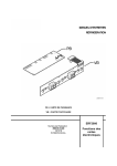
SERVICE MANUAL
REFRIGERATION
PB = POWER BOARD
VB = DISPLAY BOARD
ERF2000
© ELECTROLUX ZANUSSI S.p.A.
Spares Operations Italy
Corso Lino Zanussi, 30
I - 33080 PORCIA / PN (ITALY)
Fax +39 0434 394096
Revision: 01 (250108)
Publication no.
599 35 61-03
021218
ITZ/SERVICE/AA
Functions of the
electronic
boards
ERF2000 Functions of the electronic boards Rev. 01
2/30
CONTENTS
1. INTRODUCTION ................................................................................................................................................. 5
2. PICTURES........................................................................................................................................................... 9
2.1 PB .................................................................................................................................................................. 9
2.2 ALFA 2C....................................................................................................................................................... 10
2.3 BI 1C ............................................................................................................................................................ 11
2.4 BI 2C ............................................................................................................................................................ 12
2.5 DELTA 2C .................................................................................................................................................... 13
2.6 D3 1C ........................................................................................................................................................... 14
2.7 ALFA 1C....................................................................................................................................................... 15
3. CONTROL FUNCTIONS ................................................................................................................................... 16
3.1 Switching the appliance on and off .............................................................................................................. 16
3.2 Regulation of the freezer temperature ......................................................................................................... 16
3.3 Control of freezer compartment ................................................................................................................... 16
3.4 Fast-freezing function .................................................................................................................................. 16
3.5 Freezer compartment display ...................................................................................................................... 17
3.6 Regulation of the temperature in the refrigerator compartment................................................................... 17
3.7 Control of refrigerator compartment............................................................................................................. 17
3.8 Holiday function of the refrigerator ( only in cooler and in some cooler compartments of the twocompressor appliances ).................................................................................................................................... 17
3.9 SUPER COOLING Function of the refrigerator ........................................................................................ 18
3.10 Display of the refrigerator compartment ................................................................................................... 18
3.11 Demo Mode .............................................................................................................................................. 18
4. ALARMS ............................................................................................................................................................ 19
4.1 Freezer compartment temperature alarm ................................................................................................... 19
4.2 Refrigerator compartment temperature alarm (optional) ............................................................................ 19
4.3 Door open alarm (optional) ......................................................................................................................... 19
4.4 Electronic boards incompatibility alarm ...................................................................................................... 20
4.5 Eeprom error alarm...................................................................................................................................... 20
5. NTC-SENSORS FAULT .................................................................................................................................... 21
6. DISPLAY SYMBOLS ........................................................................................................................................ 23
7. SPECIAL FUNCTIONS ..................................................................................................................................... 25
7.1 Changing the temperature area of the freezer (optional) ............................................................................ 25
7.2 Devices check programme .......................................................................................................................... 25
7.3 Check programme of the EEPROM code, the software version and the failure code................................. 25
7.4 EEPROM Error function............................................................................................................................... 26
7.5 Fast guide to the special functions .............................................................................................................. 27
8. VERSIONS ........................................................................................................................................................ 28
8.1 Version for 4 stars........................................................................................................................................ 28
8.1.1 Fast freezing function in the 4 stars (FROSTMATIC) ........................................................................... 28
8.1.2 Balancing heater with automatic activation ( 4 stars )........................................................................... 28
8.2 Version for DYNAMIC COOLER.................................................................................................................. 28
8.2.1 Differences between the dynamic cooler model and a traditional model.............................................. 28
8.2.2 Quick Chill ............................................................................................................................................. 28
8.2.3 Effect on the loads of the door opening in DME (Dynamic Mini Evaporator) appliances ..................... 29
Appendix A ............................................................................................................................................................ 30
Revisions............................................................................................................................................................ 30
ERF2000 Functions of the electronic boards Rev. 01
3/30
ERF2000 Functions of the electronic boards Rev. 01
4/30
1. INTRODUCTION
In this manual are described the functions of the electronic boards called ERF2000 which are mounted on the
new electronic appliances.
The ERF2000 electronic control always consists of 2 separable elements:
A VB display board which feature different versions according to the functions and the styling of the
appliance. The main components are the displays, the pushbuttons, the LEDs, the door switch and a
EEPROM memory in which both the appliance state (useful in case of a power interruption) and the
control and configuration parameters of the appliance are memorized;
A PB power board which contains the micro-controller (inside which there are the 2 RAM and ROM
memories), the AC/DC transformer, the triacs of loads power, the buzzer and the protections of the
electronic board.
Aim of this manual is to fully describe the standard functions of an appliance controlled by the new ERF2000
electronic and the operation of the service mode to check the efficiency of the electronic.
Warning: the power board, the display board and all the cables (the sensor cables included)
are powered with a voltage of 220-240V 50Hz even if the ON/OFF key is set on (OFF). Therefore,
disconnect the appliance before operating on the electronic board.
ERF2000 Functions of the electronic boards Rev. 01
5/30
The ERF 2000 range features the following series of models:
ref
1
2
3
4
5
6
7
8
9
10
11
12
13
14
15
16
17
18
19
20
21
22
23
24
25
26
27
28
29
30
31
32
33
34
35
36
Electronic board
power
power
power
display
display
display
display
display
display
display
display
display
display
display
display
display
display
display
display
display
display
display
display
display
display
display
display
display
display
display
display
display
display
display
display
display
Board version
ERF2000P-01.A
ERF2000P-01.B
ERF2000P-01.C
ERF2000D-03.A
ERF2000D-03.A
ERF2000D-03.A
ERF2000D-03.A
ERF2000D-03.A
ERF2000D-03.A
ERF2000D-06.B
ERF2000D-06.B
ERF2000D-06.A
ERF2000D-06.A
ERF2000D-05.A
ERF2000D-05.B
ERF2000D-05.A
ERF2000D-01.B
ERF2000D-01.C
ERF2000D-01.C
ERF2000D-02.B
ERF2000D-02.B
ERF2000D-02.D
ERF2000D-02.D
ERF2000D-02.B
ERF2000D-02.A
ERF2000D-02.A
ERF2000D-02.D
ERF2000D-02.A
ERF2000D-02.A
ERF2000D-02.B
ERF2000D-02.A
ERF2000D-04.A
ERF2000D-04.A
ERF2000D-04.A
ERF2000D-04.A
ERF2000D-04.A
Software version
NFBF0A0R
NFBF0A0R
NFBF0A0R
-
eeprom
F004F
F0006
F0001
F0003
F005B
F0071
F002E
F002F
F0030
F0031
F0066
F0065
F0064
F005F
F0020
F0027
F0061
F0025
F0041
F0062
F0043
F005C
F005D
F005E
F0067
F0068
F0072
F0070
F0029
F002B
F002D
F0063
F0052
title
4 triacs
3 triacs
2 triacs
ALFA 2C
ALFA 2C
ALFA 2C
ALFA 2C
ALFA 2C
ALFA 2C
BI 1C
BI 1C
BI 1C
BI 1C
BI 2C
BI 2C
BI 2C
DELTA 2C
DELTA 2C
DELTA 2C
D3 1C
D3 1C
D3 1C
D3 1C
D3 1C
D3 1C
D3 1C
D3 1C
D3 1C
D3 1C
D3 1C
D3 1C
ALFA 1C
ALFA 1C
ALFA 1C
ALFA 1C
ALFA 1C
NOTE:
The power boards with 2 or 3 triacs (for the 2 and 3-load control) are interchangeable with the one featuring 4
triacs (for the 4-load control). Therefore, for unification, the power boards with 2 and 3 triacs are replaced by the
power board with 4 triacs.
ERF2000 Functions of the electronic boards Rev. 01
6/30
ref
1
2
3
4
5
6
7
8
9
10
11
12
13
14
15
16
17
18
19
20
21
22
23
24
25
26
27
28
29
30
31
32
33
34
35
36
Model
Not mounted optional components
GTH4
GTH2; GTH4;
DME MA
266 REX
316/346 ZS
316/346
MA-KSV20042 VALVE
MA-KSV18048 VALVE
ADAPTIVE COOLER AEG FI
ADAPTIVE COOLER QUELLE FI
4 STARS BI AEG
4 STARS BI QUELLE
1780 BI AEG
1780 BI QUELLE
1780 BI ELECTROLUX
COMBI 2C QUELLE MA
266 REX
316/346 REX ZS
ZS QUELLE 186/156 FZ
ZS QUELLE226 FZ
MA FZ STD QUELLE
MA FZ MAXI QUELLE
296 C ZAN
MA ELUX FSX14532
MA ELUX FSX16532 FSX18532
MA QUELLE FSX16532 FSX18532
MA AEG FSX14532
MA AEG FSX16532 FSX18532
MA ZAN COOLER STD
MA ZAN FREEZER STD
156 FZ
186 FZ
226 FZ
FZ MAXI MA
FZ STD MA
room NTC sensor; DL2; SW5;
room NTC sensor; DL2; SW5;
room NTC sensor;
room NTC sensor; DL7; SW2; SW7; DL1; SW3; DL2;
room NTC sensor;
room NTC sensor; SW5; SW9; LD3; LD6; LD1A; LD3A; LD6A; LD7A;
room NTC sensor; SW1; LD1A; LD3A; LD6A; LD7A;
room NTC sensor; SW1; LD1A; LD3A; LD6A; LD7A;
room NTC sensor; SW1; SW10; LD7; LD4A; LD6A; LD7A;
room NTC sensor SW1; SW10; LD7; LD4A; LD6A; LD7A;
room NTC sensor; SW10; LD7; LD4A; LD6A; LD7A;
room NTC sensor; SW10; LD7; LD4A; LD6A; LD7A;
room NTC sensor; SW1; LD4A; LD7; SW10; LD6A; LD7A;
room NTC sensor; LD4A; LD6A; LD7A;
room NTC sensor; LD4A; LD6A; LD7A;
room NTC sensor; SW10; LD7; LD4A; LD6A; LD7A;
room NTC sensor; LD7; LD4B; LD6/LD6B;
room NTC sensor; LD7; LD4B; LD6/LD6B;
room NTC sensor; SW10; LD4A; LD7; LD6A; LD7A;
room NTC sensor; LD4A; LD6A; LD7A;
room NTC sensor; SW1;
room NTC sensor; SW1;
room NTC sensor; SW1;
room NTC sensor;
room NTC sensor;
ERF2000 Functions of the electronic boards Rev. 01
7/30
ref
1
2
3
4
5
6
7
8
9
10
11
12
13
14
15
16
17
18
19
20
21
22
23
24
25
26
27
28
29
30
31
32
33
34
35
36
Notes
4 triacs;
3 triacs;
2 triacs;
DL1 e DGT1=red;
DL1 e DGT1=green;
DL1 e DGT1=red; DL2=yellow COOLMATIC;
DL1 e DGT1=green; DL2=yellow COOLMATIC;
DGT1,DL4,DGT2 e DL6=red;
DGT1,DL4,DGT2 e DL6=green;
DGT1,DL4,DGT2 e DL6=green;
LD2,LD5,DISP1 e DISP2=green;
LD2,LD5,DISP1 e DISP2=green;
LD2,LD5,DISP1 e DISP2=green;
LD5 e DISP2=green; LD6B=red;
LD5 e DISP2=green; LD6B=red;
LD5 e DISP2=green; LD6B=red;
LD5 e DISP2=green; LD6B=red;
LD5 e DISP2=green; LD6=yellow;
LD5 e DISP2=green; LD6=yellow;
LD5 e DISP2=green; LD6=yellow;
LD5 e DISP2=green; LD6B=red;
LD5 e DISP2=red;
LD5 e DISP2=red;
LD5 e DISP2=green; LD6=yellow;
LD5 e DISP2=green; LD6=yellow;
-
ERF2000 Functions of the electronic boards Rev. 01
Picture
PB
PB
PB
ALFA 2C
ALFA 2C
ALFA 2C
ALFA 2C
ALFA 2C
ALFA 2C
BI 1C
BI 1C
BI 1C
BI 1C
BI 2C
BI 2C
BI 2C
DELTA 2C
DELTA 2C
DELTA 2C
D3 1C
D3 1C
D3 1C
D3 1C
D3 1C
D3 1C
D3 1C
D3 1C
D3 1C
D3 1C
D3 1C
D3 1C
ALFA 1C
ALFA 1C
ALFA 1C
ALFA 1C
ALFA 1C
8/30
2. PICTURES
2.1 PB
KEY:
GTH1
GTH2
GTH3
GTH4
VDR
FUSE
T
BZ
µC
= FREEZER COMPRESSOR TRIAC;
= REFRIGERATOR COMPRESSOR TRIAC;
= LAMP TRIAC;
= FAN TRIAC;
= OVERVOLTAGE PROTECTION;
= GENERIC PROTECTION;
= TRANSFORMER;
= BUZZER;
= MICRO-CHECKER;
ERF2000 Functions of the electronic boards Rev. 01
9/30
2.2 ALFA 2C
KEY:
SW1
SW2
SW3
SW4
SW5
SW6
SW7
SW8
SW9
SW10
DISP1
DISP2
LD3
LD5
LD6
LD7
= REED ELEMENT;
= REFRIGERATOR ON/OFF BUTTON;
= REFRIGERATOR TEMPERATURE INCREASE BUTTON;
= REFRIGERATOR TEMPERATURE DECREASE BUTTON;
= REFRIGERATOR “SUPER COOLING” BUTTON;
= FREEZER ON/OFF BUTTON;
= FREEZER TEMPERATURE INCREASE BUTTON;
= FREEZER TEMPERATURE DECREASE BUTTON;
= FREEZER “SUPER” BUTTON;
= ALARM RESET BUTTON;
= REFRIGERATOR DISPLAY;
= FREEZER DISPLAY;
= REFRIGERATOR “SUPER COOLING” LED;
= SYMBOL - LED;
= FREEZER SUPER LED;
= ALARM LED;
ERF2000 Functions of the electronic boards Rev. 01
10/30
2.3 BI 1C
KEY:
SW1
SW2
SW3
SW4
SW5
SW6
DGT1
DL1
DL2
DL3
DL4
= ON/OFF BUTTON;
= TEMPERATURE INCREASE BUTTON;
= TEMPERATURE INCREASE BUTTON;
= FREEZER “SUPER” BUTTON;
= ALARM RESET BUTTON;
= REED ELEMENT;
= DISPLAY;
= SYMBOL - LED;
= ALARM LED;
= FROSTMATIC LED;
= ON/OFF LED;
ERF2000 Functions of the electronic boards Rev. 01
11/30
2.4 BI 2C
KEY:
SW1
SW2
SW3
SW4
SW5
SW6
SW7
SW8
SW9
SW10
DGT1
DGT2
DL1
DL2
DL3
DL4
DL5
DL6
DL7
= REED ELEMENT;
= FREEZER ON/OFF BUTTON;
= FREEZER “SUPER” BUTTON;
= FREEZER TEMPERATURE INCREASE BUTTON;
= FREEZER TEMPERATURE DECREASE BUTTON;
= REFRIGERATOR ON/OFF BUTTON;
= REFRIGERATOR “SUPER COOLING” BUTTON;
= REFRIGERATOR TEMPERATURE INCREASE BUTTON;
= REFRIGERATOR TEMPERATURE DECREASE BUTTON;
= ALARM RESET BUTTON;
= REFRIGERATOR DISPLAY;
= FREEZERDISPLAY;
= FREEZER “SUPER” LED;
= REFRIGERATOR FROSTMATIC LED;
= ALARM LED;
= SYMBOL + LED;
= REFRIGERATOR ON/OFF LED;
= LED SYMBOL -;
= FREEZER ON/OFF LED;
ERF2000 Functions of the electronic boards Rev. 01
12/30
2.5 DELTA 2C
KEY:
SW1
SW2
SW3
SW4
SW5
SW6
SW7
SW9
SW10
DISP1
DISP2
LD1
LD2
LD3
LD5
LD6
LD7
= REED ELEMENT;
= REFRIGERATOR-FREEZER ON/OFF BUTTON;
= REFRIGERATOR TEMPERATURE INCREASE BUTTON;
= REFRIGERATOR TEMPERATURE DECREASE BUTTON;
= REFRIGERATOR “SUPER COOLING” BUTTON;
= FREEZER TEMPERATURE DECREASE BUTTON;
= FREEZER TEMPERATURE INCREASE BUTTON;
= FREEZER “SUPER” BUTTON;
= ALARM RESET BUTTON;
= REFRIGERATOR DISPLAY;
= FREEZER DISPLAY;
= REFRIGERATOR ON/OFF LED;
= SYMBOL + LED;
= FREEZER “SUPER” LED;
= SYMBOL - LED;
= REFRIGERATOR FROSTMATIC LED;
= ALARM LED;
ERF2000 Functions of the electronic boards Rev. 01
13/30
2.6 D3 1C
KEY:
SW1 = REED ELEMENT;
SW6 = FREEZER ON/OFF BUTTON;
SW7 = FREEZER TEMPERATUER INCREASE BUTTON;
SW8 = FREEZER TEMPERATURE DECREASE BUTTON;
SW9 = FREEZER “SUPER” BUTTON;
SW10 = ALARM RESET BUTTON;
DISP2 = FREEZER DISPLAY;
LD4A/B = FREEZER ON/OFF LED;
LD5
= SYMBOL - LED;
LD6/6B = SUPER / RESET ALARM LED;
LD6A = “SUPER” LED;
LD7/7A = ALARM RESET LED;
ERF2000 Functions of the electronic boards Rev. 01
14/30
2.7 ALFA 1C
KEY:
SW1
SW6
SW7
SW8
SW9
SW10
DISP1
DISP2
LD5
LD6
LD7
= REED ELEMENT;
= FREEZER ON/OFF BUTTON;
= FREEZER TEMPERATURE INCREASE BUTTON;
= FREEZER TEMPERATURE DECREASE BUTTON;
= FREEZER “SUPER” BUTTON;
= ALARM RESET BUTTON;
= REFRIGERATOR DISPLAY;
= FREEZER DISPLAY;
= SYMBOL - LED;
= FREEZER “SUPER” LED;
= ALARM LED;
ERF2000 Functions of the electronic boards Rev. 01
15/30
3. CONTROL FUNCTIONS
3.1 Switching the appliance on and off
To start a compartment you need to press the ON/OFF button, respectively for the refrigerator and the freezer. It
starts immediately.
To switch off the compartment you need to press the ON/OFF button for at least 1 second. The switching off can
be accompanied by an optional countdown and the display shows 3, 2, 1 sequentially.
In some appliances the ON/OFF button controls the switching on of both the compartments (refrigerator and
freezer) and the switching off of the single compartment is integrated in the temperature increase button by
selecting the maximum temperature position.
By pushing the temperature decrease button, the compartment switches on again with the last set value.
3.2 Regulation of the freezer temperature
To modify the freezer set temperature, push the temperature increase or decrease button. The temperature can
be set between the values –15°C and –24°C.
Once the temperature increase or decrease button has been pressed, the display flashes for 5 seconds showing
the set temperature. It is possible to modify the set temperature by pushing the temperature increase or
decrease within these 5 seconds. The display stops flashing and shows the temperature detected inside the
freezer.
The minimum On time of the compressor is 1-2 minutes.
The minimum Off time varies from 5 to 20 minutes.
3.3 Control of freezer compartment
The switching on and off of the compressor of the freezer compartment are controlled by the air sensor of the
freezer.
3.4 Fast-freezing function
The Super function is activated through the actioning of the Super button, therefore:
the led corresponding to the Super function lights (if featured) and the display shows “A” or “SP” or the
measured temperature (depending on the models);
the compressor runs continuously for a fixed time and stops when the set Super cut-out temperature is
reached or, if this temperature is never reached, at the end of a max. prefixed time (about 52 hours).
If the button is pressed again the Super function deactivates:
the corresponding led switches off (if featured);
the compressor functions in thermostatic conditions.
In some models the fast-freezing function is activated through the actioning of the temperature decrease button
till the max cold position is reached (above -24°C). In this case to disconnect the Super function, push the
temperature increase button and select a new setting.
ERF2000 Functions of the electronic boards Rev. 01
16/30
3.5 Freezer compartment display
The thermometer indicates the temperature of the warmest part in the freezer compartment. This means that the
other temperatures of the freezer (measured through an ordinary thermometer) will always be lower than those
indicated on the thermometer. The temperature difference between the central part of the compartment (which
must not be measured in direct contact with the evaporator) and the warmest part of the freezer is included
between 3º and 7ºC. To avoid false variations from the set value a stabilization window of the displayed
temperature of +/- 3º C has been introduced. At temperatures included between this interval the set value is
indicated.
At temperatures not included between this interval the real value is indicated. The freezer thermometer updates
the shown temperature of 1º C every 4-20 min. (according to the versions) when temperature decreases and
every 4-25 min. when temperature increases.
Attention: to eliminate the updating delay of the temperature, disconnect the appliance and connect it again.
3.6 Regulation of the temperature in the refrigerator compartment
To modify the set temperature in the freezer compartment it is necessary to push the temperature increase or
decrease button. The temperature that can be set goes from +2°C up to +8°C for all the models except from
some Electrolux models by which the temperatures go from +1°C up to +9°C.
Once the temperature increase or decrease button has been pushed, the display flashes for 5 seconds showing
the set temperature. The display stops flashing and shows the temperature detected inside the refrigerator.
The min On time of the compressor in the refrigerator compartment is 1-2 min.
The min. Off time is 5 min.
3.7 Control of refrigerator compartment
The compressor is activated when both the air sensor and the evaporator sensor detect the cut-in temperature
and is deactivated when the temperature detected by the air sensor reaches the cut-out temperature.
Only for 4-star models, at low room temperatures (room temperature lower than +20°C ) a balancing heater is
automatically activated, by means of a sensor placed on the display board (VB) or the lighting lamp is switched
on partially with a 1-minute delay after the door closure.
Attention!
It is possible, therefore, that checking the efficiency of the switching off of the light, the lamp lights even if the
door is closed, this does not imply that the door light switch functions badly.
To check if the light switches off correctly, it is necessary to check if the lamp is off within 1 minute after the door
closure (after that time the lamp might be on because it is controlled by the electronic board!).
3.8 Holiday function of the refrigerator ( only in cooler and in some cooler compartments of the twocompressor appliances )
The max. temperature that can be set in the refrigerator compartment reaches +8°C (+9°C for some Electrolux
models).
Pushing again the temperature increase button after reaching +8°C (+9°C for some Electrolux models), the
symbol “H” appears on the display to indicate that Holiday function is switched on.
With the Holiday function the refrigerator temperature is kept at +14°C.
This temperature does not allow preserving the food, but it is very useful when the refrigerator compartment is
not used, since it avoids the formation of bad odours.
To deactivate the function it is necessary to set another temperature so as to the symbol “H” disappears from the
display.
ERF2000 Functions of the electronic boards Rev. 01
17/30
At the end of the Holiday function, the temperature alarm of the refrigerator compartment will be switched on
with a 2-hour delay.
3.9 SUPER COOLING Function of the refrigerator
Pushing the super cooling button of the refrigerator the super cooling function is activated and the refrigerator
temperature is automatically set at +2°C.
The function deactivates automatically after about 6 hours or by pushing the super cooling button again.
The corresponding led lights to indicate that the function is active. The display shows “SP” or “A” or the real
temperature of the refrigerator compartment (according to the models).
In some models the super cooling function can be integrated in the temperature decrease button by setting the
max. cold position.
3.10 Display of the refrigerator compartment
The thermometer indicates the average temperature in the refrigerator compartment. The temperature varies
according to the compartment type. To avoid false variations compared to the set value, a stabilization window
of the shown temperature of +/- 3º C has been introduced. The set value is indicated for the temperatures
included between this interval.
The real value is indicated for temperatures not included between this interval. The refrigerator thermometer has
an updating speed of the shown temperature of 1º C every 2-10 min. (according to the versions) both when the
temperature increases and decreases.
3.11 Demo Mode
The Demo Mode function regards the market activity and not the user.
By pushing the temperature decrease button and ON/OFF button simultaneously for 5 seconds the Demo
function is switched on.
The inside temperature of the appliance, measured by the air sensor, must be higher than +10°C because the
function may be activated. For the bi-compressors, the temperature must be higher than +10°C both in the
refrigerator and the freezer compartment.
The display board (VB) operates and shows a temperature of +5°C which flashes at a low frequency in the
refrigerator compartment display (4 seconds on and 1 off) and of -18°C in the freezer compartment display (4
seconds on and 1 off).
The light switches on when the door opens, but the compressor remains always off.
To deactivate the Demo function it is necessary to unplug the appliance or to push the temperature decrease
button and ON/OFF button simultaneously for 5 seconds.
ERF2000 Functions of the electronic boards Rev. 01
18/30
4. ALARMS
4.1 Freezer compartment temperature alarm
When the temperature on the freezer display overcomes the pre-set limit (between –8°C and –12°C according to
the versions) the alarm switches on: the temperature alarm led and the display flash and the buzzer sounds.
If the alarm reset button is pushed, the buzzer stops sounding, the display shows the maximum reached
temperature for 5 seconds and the temperature alarm led continue to flash.
Only when the temperature falls below the pre-set limit also the temperature alarm led will switch off.
If the alarm condition stops automatically without pushing the alarm reset, the buzzer stops sounding but the
temperature alarm led and the display will flash.
Pushing the alarm reset button, the temperature alarm led stops flashing, while the display will show the
maximum reached temperature for 5 seconds.
When the appliance is installed for the first time and if the freezer compartment is warm, the temperature alarm
buzzer sounds and must be switched off by pushing the relative button.
4.2 Refrigerator compartment temperature alarm (optional)
Some models feature the refrigerator compartment temperature alarm which activates when the temperature in
the refrigerator compartment overcomes the pre-set limit (between +11°C and +15°C according to the versions).
At the end of the Holiday function, the temperature alarm will be switched on with a two-hour delay.
4.3 Door open alarm (optional)
In some models the open door alarm is featured ( see the user manual of the specific model! ).
The open door alarm can be activated by a sensor (reed-element) placed on the display board (VB) which
detects the presence of a magnet placed on the refrigerator door or by a switch.
As the picture shows, the magnet can be replaced only in the built-in models (in the Free-Standing models the
magnet is foamed inside the door, therefore it cannot be replaced)
ERF2000 Functions of the electronic boards Rev. 01
19/30
The switching on times of the alarm are:
-
Freezer door: 80 seconds;
Refrigerator door: 5 minutes.
4.4 Electronic boards incompatibility alarm
If the display shows the letter E after the replacement of an electronic board (display or power), it means that
there is an incompatibility between the electronic boards and the appliance cannot operate.
To solve the problem, it is necessary to verify the spare part nos. of the electronic boards.
4.5 Eeprom error alarm
If the display shows the letter P, it means that one or more electronic boards are faulty in writing/reading the
Eeprom parameters) and the appliance cannot operate.
To solve the problem, it is necessary to replace the electronic boards (power and display).
ERF2000 Functions of the electronic boards Rev. 01
20/30
5. NTC-SENSORS FAULT
Abnormal resistance values are interpreted by the electronic as a fault sensor and the display shows a symbol.
If an air sensor is faulty, the compressor will stay on for about 20 minutes and off for 30 minutes.
In case of fault of the sensors:
Refrigerator (faulty air sensor): the refrigerator display will show symbol
Refrigerator (faulty evaporator sensor): the refrigerator display will show symbol
(depending on the electronic version)
the refrigerator continues to operate thanks only to the
indications of the air sensor (for more details please refer to
parag. 7.3).
Freezer (faulty air sensor): the freezer display will show the symbol
At extreme temperatures, alarm levels may be activated even if the sensors are not faulty. The faulty codes for
temperatures higher than + 39°C and lower than - 39°C must not be considered.
ERF2000 Functions of the electronic boards Rev. 01
21/30
The NTC sensors have the following temperature-resistance characteristic:
ERF2000 Functions of the electronic boards Rev. 01
22/30
6. DISPLAY SYMBOLS
Refrigerator
"0" – "39" steady light:
It indicates the average temperature in the refrigerator in
appliances with double display.
"0" – "9"
steady light:
It indicates the average temperature in the refrigerator in
appliances with single display.
"2" – "8"
flashing light:
It appears during the temperature setting operation. It disappears 5
seconds from the end of the temperature setting.
"1" – "9"
flashing light:
It appears during the temperature setting operation. It disappears 5
seconds after the end of the temperature setting (some Electrolux
models).
"-"
steady light:
It indicates that the refrigerator temperature is higher than 9°C and
the display is single.
"0"
steady light:
It indicates that the refrigerator temperature is between -2°C and
0°C.
"-"
flashing light:
It indicates that the refrigerator temperature is lower than -2°C.
"H"
steady light:
It indicates the Holiday function.
"A" or “SP” steady light:
It indicates the super cooling function.
steady light:
Air sensor fault.
steady light:
Evaporator sensor faulty.
“E”
steady light:
It indicates incompatibility between the electronic boards.
Solution: check the part nos. of the electronic boards.
“P”
steady light:
It indicates an Eeprom error (wrong or not readable parameters).
Solution: replace both electronic boards (power and display).
ERF2000 Functions of the electronic boards Rev. 01
23/30
Freezer
"+39" – "-39" steady light:
It shows the highest temperature in the freezer.
"-15" – "-24" flashing light:
It is indicated during the temperature setting operation. It
disappears 5 sec after the end of the temperature setting.
"+39" – "-39" flashing light:
It appears when the freezer temperature is higher than the alarm
value (between - 8°C and -12°C according to the models) and
when this temperature is returned to lower value after the alarm.
"+39" – "-8"
steady light:
It indicates the highest temperature in the compartment after a
current interruption (shown for 5 sec after pushing reset button.
Simultaneously the pilot lamp switches off).
"A" o “SP”
steady light:
It indicates the super cooling function.
steady light:
Air sensor fault in the freezer.
“E”
steady light:
It indicates incompatibility between the electronic boards.
Solution: check the part nos. of the electronic boards.
“P”
steady light:
It indicates an Eeprom error (wrong or not readable parameters).
Solution: replace both electronic boards (power and display).
ERF2000 Functions of the electronic boards Rev. 01
24/30
7. SPECIAL FUNCTIONS
7.1 Changing the temperature area of the freezer (optional)
The changing can be carried out currently only for the models produced in Mariestad (Sweden).
If the customer experiences excessive deviations between measured and displayed temperatures, the
technician can decrease the temperature area of 3ºC.
To obtain this variation, with the appliance on, it is necessary:
1. Press the Super button and the freezer temperature increase simultaneously or press the increase button
and decrease button simultaneously for at least 5 seconds. (this variant has been necessarily introduced
because in some versions the Super button is not featured).
2. After 5 seconds the buzzer sounds with a long signal, which confirms that the temperature area has been
decreased.
In this way the displayed temperature is reduced by 3º C. For the same set temperature the compressor will
function between cut-in and cut-out temperatures increased by 3º C. In this way an average temperature is
displayed and not the temperature of the warmest part in the freezer compartment.
To display again the normal temperature, repeat the same operations described in point 1. Now the buzzer will
sound with a short signal to confirm that the original conditions have been reset.
7.2 Devices check programme
This function enables to check if all the Leds and some loads operate correctly.
To activate this function it is necessary disconnect the power supply of the appliance, and then:
Press the temperature increase button within 15 seconds after the connection of the power supply to the
appliance;
Wait 5 seconds before releasing the button.
- The buzzer sounds with a long signal, all the Leds and the digits of the display board (VB) are on and all the
loads of the power board are activated;
- By opening the door the alarm Led switches off; for the 4 stars appliances the Super Led switches off;
- When one of the buttons is pressed the buzzer sounds and, if the evaporator sensor is featured, the
temperature measured by this sensor is displayed. This is the only way to display the temperature measured by
the evaporator NTC sensor.
- If a NTC sensor is disconnected, the display and the LEDs flash (this is valid only for the two-compressor
appliances).
The control programme is interrupted automatically after 1 minute and the compartment returns to normal mode.
7.3 Check programme of the EEPROM code, the software version and the failure code
It is possible to display a sequence of digits containing:
1) EEPROM code,
2) the software version code of the power board and
3) a failure code of the temperature NTC sensors.
To activate this function it is necessary to disconnect the appliance from the power supply, press the freezer
temperature decrease button for 5 seconds (if cooler the refrigerator temperature decrease button) within 15
seconds after the reconnection of the power supply to the appliance.
Once this function has been activated the following operations are carried out automatically:
- The display switches off and the buzzer sounds with a long signal.
- The display shows the last 4 digits of the EEPROM code alternated by a short signal of the buzzer. The last
displayed digit is not followed by a short signal.
- The display switches off and the buzzer sounds with a long signal.
ERF2000 Functions of the electronic boards Rev. 01
25/30
-
The display shows the software version which consists of the last six digits/letters in sequence alternated
by a short signal of the buzzer. The last displayed digit is not followed by a short signal.
The display switches off and the buzzer sounds with a long signal for the third time.
The display shows the letter E followed by a short signal of the buzzer and then a digit (failure code)
The display switches off and the buzzer sounds with a long signal for the fourth time.
The display returns to a normal condition.
The failure codes currently activated are:
- E1: error in the evaporator NTC sensor;
- E2: error in the room temperature NTC sensor;
- E3: error in the evaporator NTC sensor and in the room temperature NTC sensor.
Example:
If the software code is NFBC0A01, the EEPROM code is C0002 and a failure of the room NTC sensor is
detected, with this procedure the following operations are carried out:
1)
2)
3)
4)
5)
6)
7)
8)
9)
10)
11)
12)
13)
14)
15)
16)
17)
18)
19)
20)
21)
22)
23)
24)
25)
26)
The display clears and the buzzer sounds with a long signal
The display shows 0 (EEPROM code)
The buzzer sounds with a short signal
The display shows 0 (second digit EEPROM code)
The buzzer sounds with a short signal
The display shows 0 (third digit EEPROM code)
The buzzer sounds with a short signal
The display shows 2 (fourth digit EEPROM code)
The display clears and the buzzer sounds with a long signal
The display shows b (software code)
The buzzer sounds with a short signal
The display shows C (software code)
The buzzer sounds with a short signal
The display shows 0 (software code)
The buzzer sounds with a short signal
The display shows A (software code)
The buzzer sounds with a short signal
The display shows 0 (software code)
The buzzer sounds with a short signal
The display shows 1 (software code)
The buzzer clears and the buzzer sounds with a long signal
The display shows E (software code)
The buzzer sounds with a short signal
The display shows 2 (software code)
The display clears and the buzzer sounds with a long signal
The display returns to a normal condition
7.4 EEPROM Error function
If the system detects a reading or writing error of the EEPROM parameters, the system activates the following
procedure:
The default EEPROM parameters are loaded
The letter P is displayed
It deactivates the open door alarm
It is possible to check if an error has occurred in the EEPROM memory and to activate this test function it is
necessary to push Super button within 1 min after the switching on (the Super button must be switched off).
If an EEPROM error occurs the buzzer sounds with a long signal (5 seconds).
ERF2000 Functions of the electronic boards Rev. 01
26/30
7.5 Fast guide to the special functions
In the table below are described, shortly, all the special functions for the user and the Service technicians.
Function
Starting
conditions
Function activation
Function
interruption
Short description / Notes
Buttons
Temperature field
Appliance
variation of the
connected
and
freezer
ON
(Sweden models)
Super Temperature
decrease
+
Temperature increase
for 5 sec
Appliance ON
After 5 sec the buzzer sounds with a long signal confirming that temperature is
decreasing.
By repeating the operation the buzzer sounds with a short signal and resets at
the starting conditions.
ON
SERVICE
EEPROM Error
Appliance ON
Super button within
one minute
Disconnect
EEPROM Code
Software version and reconnect
Fault code
the appliance
Temperature decrease
for 5 sec. within 15
sec after reconnection
of the appliance
LEDs controls
and loads
Disconnect
and reconnect
the appliance
Temperature increase
for 5 sec. Within 15
sec after reconnection
of the appliance
Demo
Mode
Compartment
internal
temperature
higher than
10°C
Temperature decrease
+
On/Off button
for 5 sec
ERF2000 Functions of the electronic boards
Appliance ON
At the end of
the procedure it
returns
automatically to
a normal
condition
Programme
interrupted
automatically
after 1 min.
Disconnect the
appliance or
repeat the
operation of
activation
If an EEPROM error has occurred the buzzer sounds with a long signal;
The display switches off, the buzzer sounds with a long signal; the display
shows 4 digits of EEPROM code alternated by a short signal; the last digit is
not followed by a short signal: the display switches off, the buzzer sounds with
a long signal; the display shows digits/letters of the software version code
alternated by a short signal of the buzzer: the last digit is not followed by a
short signal; the display switches off, the buzzer sounds with a long signal; the
display shows letter E; then the buzzer sounds with a short signal and fault
code appears; the display switches off and buzzer sounds with a long signal.
The buzzer sounds with a long signal, all LEDs and digits of the display board
are on; all the loads of the power board are on; by opening the door alarm LED
switches off (for the 4 star appliances the led Super switches off); when an
alarm button is pressed it sounds, and if the evaporator sensor is featured, the
evaporator temperature is displayed.
The display board is on; refrigerator compartment display shows +5°C and
freezer compartment -18°C at low frequency; by opening the door the light
switches on; compressor always Off
27/30
8. VERSIONS
8.1 Version for 4 stars
The description of the functions is the same as of the refrigerator compartment with the only difference for the
fast freezing function and the introduction of a balancing heater with automatic activation.
8.1.1 Fast freezing function in the 4 stars (FROSTMATIC)
The function activates by pushing fast freezing button, the corresponding led lights and, if activated, the letter
“A” appears on the display.
With this function the temperature is automatically set at +3°C for about 48 hours.
If you want to deactivate the function before time expires, just press the fast freezing button again.
By activating this function the balancing heater is powered or the refrigerator compartment lamp with full power.
The compressor is not powered continuously but functions with particular thermostatic conditions (temperature
control of +3°C) .
8.1.2 Balancing heater with automatic activation ( 4 stars )
The 4 star model features a balancing heater which is automatically activated when the NTC room sensor,
placed on the display board (VB), detects a room temperature lower than +15°C.
Without the balancing heater, it has been decided to power the internal lamp partially to obtain the same result
with a 1 minute delay after the door closure.
8.2 Version for DYNAMIC COOLER
8.2.1 Differences between the dynamic cooler model and a traditional model
The Dynamic Cooler models are featured with a fan which distributes the air in the refrigerator compartment
uniforming the temperatures and reducing to 1°C the temperature vertical gradient of the compartment.
This fan switches on immediately when the cut-in temperature both of the of the NTC air sensor and of the
evaporator NTC sensor while the compressor starts with some delay (2 min).
At first start of the compartment the fan and the compressor are powered at the same time.
When the air sensor reaches the cut-out temperature the compressor switches off and with some delay also the
fan (5 min).
Whenever the door is opened the fan switches off immediately while the compressor switches off with some
delay.
After 18 hours of operation of the compressor a forced defrosting procedure of the evaporator is started which
lasts 45 minutes and during which the fan is switched on and the compressor switched off.
During this extra defrosting the shown temperature value is fixed and the same as the last displayed value
before the start of this defrosting. In some versions the display shows the letter “C”.
8.2.2 Quick Chill
In these models it is possible to activate the Quick Chill function by pressing the relative button; with this mode
the fan functions continuously, the appliance operates with a set temperature of 2°C and the display shows the
letter “C”.
ERF2000 Functions of the electronic boards
28/30
8.2.3 Effect on the loads of the door opening in DME (Dynamic Mini Evaporator) appliances
When the door is opened it occurs as follows:
The fan is immediately stopped;
If the door remains open for more than a minute, the compressor stops.
ERF2000 Functions of the electronic boards Rev. 01
29/30
Appendix A
Revisions
REVISION
DATE
DESCRIPTION
00
10/2007
Document creation
01
01/2008
Added symbol of evaporator sensor faulty in chapters 5 and 6
ERF2000 Functions of the electronic boards Rev. 01
30/30