1
STRATA2
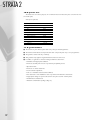
6.2 appliance operation
A
B C
D
1
2
0
E
H
I
I
3
4
F
G
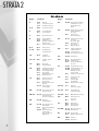
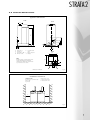
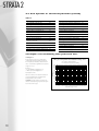
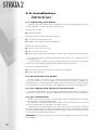
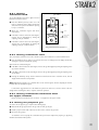
A Double pole on/off switch (main)
F Lower burner status panel
B Lower burner on/off switch
G Upper burner status panel
C Upper burner on/off switch
H RVA 47 cascade control manager
D Fuse holder
I
E Altitude gauge
Knockout for additional
optional controls
Fig 6.2a
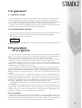
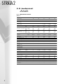
6.2.1 left switch panel
Refer to Figure 6.2a
The switch panel contains the main switch (A), this switches the entire power supply to the unity and
all connected controllers on and off. The main switch also disconnects the power to all connected pumps
and valves etc.
The second switch (B) only switches the lower heat exchanger on and off, allowing the upper heat
exchanger to continue functioning.
The third switch (C) only switches the upper heat exchanger on and off allowing the lower heat
exchanger to continue functioning.
At the right hand side is a glass fuse (D) protecting the entire unit and all connected components. This
is a 6.3AT type fuse.
At the bottom of this panel is a manometer (E) which indicates the pressure in the central heating
system that is connected to the boiler.
Note: The minimum pressure must be above 0.5 bar, while the maximum pressure is 4 bar.
6.2.2 module control panels
This control panel is divided into two sections, the left hand section serving the lower heat exchanger
module and the right hand section which serves the upper heat exchanger module.
Each section has the following controls:
● Reset Button – In case of a fault, the unit can be restarted by pressing this button. In general the
fault must be rectified prior to restarting.
● Chimney Sweep Button (Commissioning button) – Pressing this button once will activate the
burner at minimum capacity (10kW). A letter ‘L’ will appear in the display window. Pressing this button
twice will increase the capacity of the burner up to its maximum (60kW). A letter ‘H’ will appear in the
display window. Pressing this button a third time will return the unit to its previous operating condition.
If the button is not pressed a third time, the unit will fire at the chosen level for a period of 10 minutes,
following which it will revert to auto operation.
● Test Button – Pressing this button will stop the unit burning. Releasing the button will allow the unit
to restart again after a short time. The purpose of this button is to provide a simple method of testing
the start-up behaviour of the unit and to test the safety circuit.
Note: If the unit does not switch off, the wiring harness must be checked for short circuits, or the
maximum thermostat or the printed circuit of the burner must be replaced.
● Display – The display will always show one of the following situations.
Supply Temperature
Operating messages:- these are always indicated by one digit
Faults:- these are always indicated by two flashing digits
28
If there are no faults present in the unit, the display will show the supply temperature. When the burner
is firing and functioning properly, a ‘dot’ is shown beside the supply temperature – indicating a correct
rectification signal.