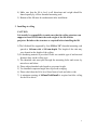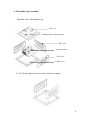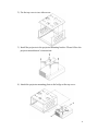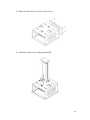
1
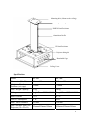
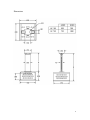
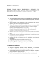
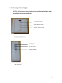
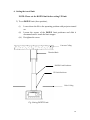
Xtension Lift
Model: AC-310
AC-510
Installation Instructions
0 XTENSION LIFT
INSTALLATION INSTRUCTIONS
Please read installation instructions carefully before installation and keep it
for future reference.
INDEX:
Important Safety Instructions………………………………………….….….2
X tension Lift Overview…………………..…………….…..………..............3
Specifications………………………………………………………............... 4
Dimensions…………………………………………………………….......…5
Installation Instructions
1. Preliminary Checking……………………………………………...…...6
2. Guidelines for Installations…………………………………………..... 6
3. Installation on Ceiling…………………………………………………..7
4.Connecting to Power Supply……………………………………..…..…9
5. Installation of Projector……………………………………...……........9
6. Cable Management……………………………………….…………...10
7. Installation of Lower Ceiling Cover…………...………………..… ....10
8. Adjusting the positions…………………………………………..........11
9. Optional Accessories………………………………………..…….... ..15
The information in this manual is subject to change without any prior notice.
Updated on March 9, 2011
1 Installation and Operation Manual
This manual explains how to install, operate and maintain the Xtension Lift for
video projector. This manual is for installer, interior designer, architect, M&E
consultant and system integrator who has known about XLT Xtension lift.
IMPORTANT SAFETY INSTRUCTIONS
WARNING: FAILURE TO FOLLOW ALL THE FOLLOWING
INSTRUCTIONS CAN RESULT IN SERIOUS PERSONAL INJURY OR
DAMAGE TO EQUIPMENT.
CAUTION
1) The lift is not for outdoor use.
2) Do not install the lift on adjacent ceiling or light fixture.
3) The equipment is not to be used by children or persons with reduced
physical, sensory or mental capabilities, or lack of experience and
knowledge, unless they have been given supervision or instructions.
4) Please do not allow children being supervised to play with the equipment.
5) Entire bottom of the lift must be unobstructed to allow proper operation.
6) The lift must be installed in level from front-to-back and side-to-side.
7) Please do not attach any projector with the weight above maximum
weight capacity.
WARNING
1) Please read the instruction before installation. Improper installation could
lead to serious injury or damage to the lift.
2) Do not obstruct the operation of the lift with hands or any other object. It
may cause serious injury or damage.
3) Keep hands and other objects away from the mechanism when the lift is
operating. Serious injury or damage could result.
2 4) Clear all persons and obstructions along the lift travel path while it is
operating or in service.
5) Watch the moving projector lift and keep people away until the projector
lift is completely closed.
6) Please do not close the lift while the projector is running or while it is in
“cool down” operation to avoid premature failure of electrical or
electronic components.
7) Please do not step on the lift or cage. Overloading could lead to damage
of equipment or injury.
ELECTRICAL RISK
1) Please check the standard of the local power supply before installation
and ensure that the operation voltage of the motor is related to the local
power supply. The motor may damage due to incorrect voltage supply.
2) Never operate the lift with damaged or faulty cord or plug.
3) Please keep the cord away from heated surface.
4) Please turn off power supply before cleaning or servicing.
The Xtension Lift
Overview
The lift is powered by a linear actuator which is operated on Single phase
230~240 V AC 50 Hz. It provides an attractive solution to recess a projector in
ceiling or conference table and it can be extended to projection level.
The lift is shipped with the carton box and the following items are allocated.
Please inspect them for any damage when receive the lift.
1)
2)
3)
4)
5)
The Xtension lift
IR transmitter and remote control
Projector cage (Detachable)
User Manual
A package of screws for projector
3 Mounting hole ( Mount to the ceiling)
Ceiling Mounting Plate
DOWN Limit Positioner
Aluminium Profile
UP limit Positioner
Projector tilting kit
Detachable Cage
Ceiling Cover
Specification:
Model
AC 310
AC 510
Dimension (W x D)
Height in Closed
Position (w/o cage)
Max. Weight Capacity
210mmx150mm
210mmx150mm
530mm
730mm
20 kg
20 kg
Voltage
Single Phase 230VAC50 Hz Single Phase 230VAC 50 Hz
Rated Current
0.2 A
0.2 A
Power Consumption
45 W
45W
Max. Travel Distance
Max. available Space for
Projector (W x D x H)
350 mm
550 mm
450mmx450mmx190mm
450mmx450mmx190mm
4 Dimensions
5 Installation Instructions
PLEASE ENGAGE LOCAL PROFESSIONAL INSTALLER TO
PERFORM INSTALLATION. PLEASE ALWAYS FOLLOW LOCAL
BUILDING CODES, ELECTRICAL CODES AND LOCAL LAWS.
1. Preliminary Checking:
1) The ceiling structure should support at least FOUR times the total weight
of the lift and projector. Please reinforce additional supporting structure if
needed.
2) Please check the overall dimensions of the lift and ensure that there is
sufficient space above ceiling before installation.
3) 100mm (4″) clearances from all surrounding structures are recommended.
The minimum ceiling space required for the lift to install at ceiling is
680mmWx680mmDx850mmH for AC 310 and
680mmWx680mmDx1050mmH for AC 510. The installer must be
accessible to every side in order to install the lift.
4) Check the dimensions of the projector to be mounted within the available
space.
5) Determine the projector installation position based on projection screen
location and projector specifications.
6) Confirm that there is adequate space for installation, operation and
maintenance.
7) Arrange the space for service and the access to the lift.
8) Confirm height of ceiling with maximum travel of the lift.
9) Physically check for any damages or loose parts on the lift.
2. Guidelines for Installation:
1) Read the instructions carefully before installation. An incorrect
installation could lead to serious injury or damage to the lift.
2) Installer must ensure that all fasteners support have adequate strength to
securely support the lift and projector.
3) The lift must be installed in level from front-to-back and side-to-side.
6 4) Make sure that the lift is level in all directions and weight should be
shared equally by all four threaded mounting rods.
5) Bottom of the lift must be unobstructed after installation.
3. Installing at ceiling
CAUTION:
It is installer’s responsibility to make sure that the ceiling structure can
support at least FOUR times the total weight of the lift and the
projector. Reinforce the structure as required before installing the lift.
1) The lift should be supported by four M10 or 3/8″ threaded mounting rods
spaced at 160 mm wide x 100 mm depth. The length of the rods may
vary depend on the height of the ceiling.
2) No mounting material is provided. Please use suitable type of anchors and
fasteners base on the ceiling type.
3) The threaded rods must pass through the mounting holes and secure by
nuts above and below.
4) Please adjust threaded rods length to get proper height.
5) Use threaded compound angle nuts to prevent swinging.
6) Please check that the lift is level from front to back and side to side.
7) A minimum opening of 485mmWx485mmD is required on false ceiling
for the lift to travel.
7 4. Detachable Cage Assembly
Exploded view of detachable cage
Top Cover
Mounting hole to attach projector
Back cover
Projector bracket
Side Cover
Ceiling Cover
1) Fix left and right side cover to the ceiling cover frame.
8 2) Fix the top cover to two side covers.
3) Install the projector to the projector mounting bracket. Please follow the
projector manufacturer’s instructions.
4) Attach the projector mounting plate to the bridge at the top cover.
9 5) Please fix the back cover to two side covers.
6) Attach the cage to the ceiling mounted lift.
10 5. Connecting to Power Supply
NOTE: All electrical wiring required for installation should be done
by qualified electrical technician.
‘ UP’ button switch
‘STOP’ button switch
‘DOWN’ button switch
Wall Mount IR Reciever
‘UP’ button
‘STOP’ button
‘DOWN’ button
IR Transmitter
11 1) Please refer wiring diagram shown below.
IR switch ( Top)
12 6. Setting the travel limit
NOTE: Please set the DOWN limit before setting UP limit.
2) To set DOWN limit (show position),
(i)
(ii)
(iii)
Lower down the lift to the operating position with projector turned
on.
Loosen the screws of the DOWN limit positioner and slide it
downward until it touch the limit stopper.
Re-tighten the screw.
Concrete Ceiling
Threaded Rods
DOWN Limit Positioner
UP Limit Positioner
False Ceiling
Fig. Setting DOWN Limit
13 3) To set UP limit (store position),
(i) Bring the lift up to the store position or flush with the ceiling
board.
(ii) Loosen the screws of the UP limit positioner and slide it upward
until it touch the limit stopper
(iii) Re-tightened the screw.
Concrete Ceiling
Threaded Rods (x4)
Down Limit Positioner
UP Limit Positioner
False Ceiling
Fig. Setting UP limit
4) Please operate the lift UP and DOWN to counter check the limit setting.
5) Make sure that projector’s cables are long enough to travel up and down.
6) Please put all the projector cables inside the cable carrier.
7) The projector should be adjusted at the screen level as necessary.
14