1
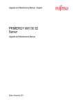
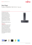
OWNERS MANUAL WK-3 / WK-4 KeyPads WK-3 WK-4 McIntosh Laboratory, Inc. 2 Chambers Street Binghamton, New York 13903-2699 Phone: 607-723-3512 FAX: 607-724-0549 Thank You, Please Take A Moment, and Customer Service Thank You Customer Service For your decision to own this McIntosh WK-3 / WK-4 Keypad ranks you at the very top among discriminating music listeners. You now have The Best. The McIntosh dedication to Quality, is assurance that you will receive many years of musical enjoyment from this unit. Please take a short time to read the information in this manual. We want you to be as familiar as possible with all the features and functions of your new McIntosh WK-3 / WK-4. This will ensure that you receive all the performance benefits this equipment can offer you, and that it will become a highly valued part of your home entertainment system. If at any time you have questions about your McIntosh WK-3 / WK-4, contact your McIntosh dealer. Your dealer is familiar with your McIntosh equipment as well as other brands that may be included in your system and is best qualified to help you. Please Take A Moment The serial number, purchase date and McIntosh dealer name are important to you for possible insurance claim or future service. The serial number is located on the rear panel of the equipment. The spaces below have been provided for you to record that information: If it is determined that your WK-3 / WK-4 is in need of repair, you can return it to your dealer or you can return it to McIntosh Laboratory. Contact the McIntosh Repair Department for assistance at, McIntosh Laboratory, Inc. 2 Chambers Street Binghamton, New York 13903 Phone: 607-723-3512 FAX: 607-724-0549 Serial Number: Purchase Date: Dealer Name: Copyright 1998 by McIntosh Laboratory, Inc. 2 Table of Contents and Safety Instructions Table of Contents Thank You.............................................. 2 Please Take a Moment ........................... 2 Customer Service ................................... 2 Table of Contents ................................... 3 Safety Instructions ................................. 3 Introduction ........................................... 5 Performance Features ............................ 5 WK-3 Installation .................................. 6 WK-4 Installation .................................. 7 How to Connect the WK-3 Keypad ....... 8 How to Connect the WK-4 Keypad ....... 9 WK-3 Front Panel Push-Buttons ......... 10 WK-4 Front Panel Display and Push-Buttons ................................. 11 How to Operate the WK-3 and WK-4 . 12 Specifications ...................................... 15 Packing Instruction .............................. 15 NOTES: 1. As soon as a WK-4 installation is complete and the system power is turned on, momentarily press the RESET push-button to clear the microprocessors before further setup is attempted. 2. For additional connection information, refer to the owners manual(s) for any component(s) connected to the WK-3 / WK-4 Keypads. 3. Up to four sensors or keypads can be wired in parallel for a single zone. 4. If AC power is interrupted to the WK-4 system, all clock and timed functions will be retained for approximately 1 hour. IMPORTANT SAFETY INSTRUCTIONS! PLEASE READ THEM BEFORE OPERATING THIS EQUIPMENT. WARNING SHOCK HAZARD - DO NOT OPEN. AVIS RISQUE DE CHOC NE PAS OUVRIR. NO USER-SERVICEABLE PARTS INSIDE. REFER SERVICING TO QUALIFIED PERSONNEL General: 1. Read all the safety and operating instructions, contained in this owners manual, before operating this equipment. 2. Retain this owners manual for future reference about safety and operating instructions. 3. Adhere to all warnings and operating instructions. 4. Follow all operating and use instructions. 5. Warning: To reduce risk of fire or electrical shock, do not expose this equipment to rain or moisture. This unit is capable of producing high sound pressure levels. Continued ex3 Safety Instructions, cont posure to high sound pressure levels can cause permanent hearing impairment or loss. User caution is advised and ear protection is recommended when playing at high volumes. 6. Do not use attachments not recommended in this owners manual as they may cause hazards. Installation: 7. Locate the equipment away from heat sources such as radiators, heat registers, stoves, or other appliance (including amplifiers) that produce heat. 8. Mount the equipment in a wall or cabinet only as described in this owners manual 9. Do not use this equipment near water; for example, near a bathtub, washbowl, kitchen sink, laundry tub, in a wet basement or near a swimming pool, etc. Connection: 10. Connect this equipment only as outlined in this owners manual Care of Equipment: 11. Clean the instrument by dusting with a dry cloth or a with a cloth moistened with a window cleaner. Do not use liquid cleaners or aerosol cleaners. 12. Never spill liquids into the equipment. 4 Repair of Equipment: 13. Refer servicing to a qualified service personnel under the following conditions: A. Objects have fallen, or liquid has been spilled into the equipment. B. The equipment has been exposed to rain or water. C. The equipment does not operate normally by following the operating instructions contained within this owners manual. Adjust only those controls that are covered by the operating instructions, as an improper adjustment of other controls may result in damage and will often require extensive work by a qualified technician to restore the product to its normal operation. D. The equipment has been dropped or damaged in any way. E. The equipment exhibits a distinct change in performance - this indicates a need for service. 14. Do not attempt to service beyond that described in the operating instructions. All other service should be referred to qualified service personnel. 15. When replacement parts are required, be sure the service technician has used replacement parts specified by McIntosh or have the same characteristics as the original part. Unauthorized sub- Introduction and Performance Features stitutions may result in fire, electric shock, or other hazards. 16. Upon completion of any service or repairs to this product, ask the service technician to perform safety checks to determine that the product is in proper operating condition. Introduction The McIntosh WK-3 and WK-4 keypads allow convenient push-button remote control of McIntosh Control Centers or Multizone Control Systems. WK-3 / WK-4 Performance Features · Built-in IR sensor Adds the convenience of operating a component with a remote control in a local zone. · Multiple Inputs Select any available audio/video source in a local zone. · Transport Control Perform operating functions on a CD player, Laser Video Disc Player or tape recorder. · Wakeup Source and Volume Select the signal source and volume level that is active when a zone is turned on. · Power Off of Local Zone and System Turn off a local zone, or turn off the entire system. WK-4 Additional Performance Features · Built-in Clock and Timer The clock display indicates the time of day, as well as the on and off set times of special events. · Preset Timed Events Enjoy listening to a signal source for a specific time using the timed event turn on and turn off feature. · Local Volume Control Adjust local zone volume level up or down. Sleep Mode Set a turn off or sleep time in 10 minute intervals up to one hour. · Illuminated Push-Buttons Input, and power push-buttons illuminate to indicate zone status and selected signal source. · · Home Controller Use the Home and Numbered push-buttons to operate source components controlled by the optional HC-1 Home Controller. 5 WK-3 Installation WK-3 Installation The WK-3 can be custom installed in a wall opening, piece of furniture or cabinet of your choice. The WK-3 will fit in a standard NEMA, 1-gang, sheet-steel or non-metallic outlet box with a depth of 21/2 inches. The WK-3 can be mounted directly to a wood or plasterboard wall by making a cutout according to the dimensions shown below. Plastic screw anchors are supplied for installation in plasterboard. Make sure the mounting surface is flat so the keypad does not bend or deform as the screws are tightened. Do not install the WK-3 directly above a heat generating object such as a radiator. WK-3 Mounting Cutout Detail 6 WK-3 Top View WK-3 Side View WK-4 Installation WK-4 Installation The WK-4 can be custom installed in a wall opening, piece of furniture or cabinet of your choice. The WK-4 will fit in a standard NEMA, 3-gang, sheet-steel or non-metallic outlet box with a depth of 21/2 inches. The WK-4 can be mounted directly to a wood or plasterboard wall by making a cutout according to the dimensions shown below. Plastic screw anchors are supplied for installation in plasterboard. Make sure the mounting surface is flat so the keypad does not bend or deform when the screws are tightened. Do not install the WK-4 directly above a heat generating object such as a radiator. WK-4 Top View WK-4 Side View WK-4 Mounting Cutout Detail 7 How to Connect the WK-3 to the CR12 and MX130 How to Connect the WK-3 to the CR12 How to Connect the WK-3 to the MX130 1. Connect one end of a shielded 4 conductor cable from the keypad connector to the CR12 terminal connector, according to the Pin Numbers listed below. 1. Connect one end of a shielded 4 conductor cable from the keypad connector to the MX130 terminal connector, according to the Pin Numbers listed below. Five Pin Terminal Connector Keypad Cable Connections MX130 Terminal Connector Pin # Keypad Pin # Supply Voltage Positive 1 1 Supply Voltage Ground 2 2 Signal Data - Area A 3 4 4 Signal Data - Area B 4 4 5 Cable Shield 5 3 Signal Data Ground 5 5 Keypad Cable Connections CR12 Terminal Connector Pin # Keypad Pin # Supply Voltage Positive 1 1 Supply Voltage Ground 2 2 Cable Shield 3 3 Signal Data 4 Signal Data Ground 5 McIntosh CR12 System Controller 8 Note: There is only one terminal connector for connecting keypads from both Area A and Area B to the back of the MX130. McIntosh MX130 Tuner/Control Center WK-3 Keypad WK-3 Keypad 54321 54321 How to Connect the WK-4 to the CR12 and MX130 How to Connect the WK-4 to the CR12 How to Connect the WK-4 to the MX130 1. Connect one end of a shielded 4 conductor cable from the keypad connector to the CR12 terminal connector, according to the Pin Numbers listed below. 1. Connect one end of a shielded 4 conductor cable from the keypad connector to the MX130 terminal connector, according to the Pin Numbers listed below. Five Pin Terminal Connector Keypad Cable Connections MX130 Terminal Connector Pin # Keypad Pin # Supply Voltage Positive 1 1 Supply Voltage Ground 2 2 Signal Data - Area A 3 4 4 Signal Data - Area B 4 4 5 Cable Shield 5 3 Signal Data Ground 5 5 Keypad Cable Connections CR12 Terminal Connector Pin # Keypad Pin # Supply Voltage Positive 1 1 Supply Voltage Ground 2 2 Cable Shield 3 3 Signal Data 4 Signal Data Ground 5 McIntosh CR12 System Controller WK-4 Keypad 54321 Note: There is only one terminal connector for connecting keypads from both Area A and Area B to the back of the MX130. McIntosh MX130 Tuner/Control Center WK-4 Keypad 54321 9 WK-3 Front Panel Push-Buttons WK-3 Front Panel Push-Buttons IR sensor Select any of five signal sources Turns entire system off Turns the zone you are in on or off 10 Perform operating function on a Tuner, CD player or Laser Disc Player Adjusts volume up or down in the zone you are in WK-4 Front Panel Display and Push-Buttons WK-4 Front Panel Display and Push-Buttons Indicates a timed event Indicates that the has been programmed sleep mode is active and the timer is on Indicates the Sets Hours, Indicates the time of day, Minutes for ON or OFF of sleep mode or clock and a timed event a timed event timed events Select any of eight signal sources IR sensor Activates the Sleep Mode Select CD or Laser Video Disc player functions, tape recorder functions or tuner preset review Activates the Timer Mode Sets the On and Off time for an event Mutes the audio in the zone you are in Turns the entire system on or off Turn the zone you are in on or off Set clock and timed events Resets the Microprocessor and clock functions Turns power On/Off to a component connected via a data port or McIntosh Remote Control Translator Operate the optional HC-1 Home Controller Select AM or FM Tuner functions, or Disc/Track functions on a CD or LD player Perform function on a component connected with a Remote Control Translator Adjusts volume up or down in the zone you are in Tunes to the next radio station or TV channel Select tuner presets or any numbered operation 11 How to Operate the WK-3 and WK4 How to Operate the WK-3 and WK4 Input Push-buttons Press to turn on a local zone and select a desired signal source. The selected source push-button will illuminate. IR Sensor Aim a Remote Control toward the built-in sensor to perform operating functions. WK-3 Note: Refer to figure 1 for the WK-3 and figure 2 for the Wk-4. Transport Operations Press Play. Stop or Next (next track)/Rev to operate a CD player Video disc player or tape recorder. Tuner Operations When a McIntosh tuner is being used, press Next/Rev (Review) to cycle through the tuner presets. System Off Press the Sys Off Push-button to turn off the entire system including the local zone. Power Press the Power push-button to turn On or Off the local zone. Note : When a zone is muted the Power push-button blinks on and off. to indicate muting is active. Volume Press an up or down Volume push-button to raise or lower the volume in the local zone. 12 Figure 1 WK-4 Additional Functions Mute Press the Mute push-button to mute audio in the local zone. The Power push-button will blink on and off to indicate muting is active. Press again to unmute. 0-9 Numbered Push-buttons Press a number push-button to operate the optional McIntosh HC-1 Home Controller, select tracks on a CD or laser video disc, tuner presets or any numbered operation. Tuner operations Press AM or FM to select the desired broadcast band. Press Channel up or down to tune up or down the broadcast band. Press Review to cycle through the tuner presets. Transport Operations Press Stop, Back (backtrack), Next (next How to Operate the WK4 cont track) or play to operate a CD player, Video Disc player or tape recorder. Press Acc On push-button to turn AC power of a McIntosh MLD720 Video Disc player on and off. Disc and Track The Disc (AM) and Track (FM) push-buttons can be programmed to perform transport operations when a component is connected using the RCT-3 emote Control Translator. Reset Push-Button The RESET push-button performs the following. 1. Press and hold for 3 seconds or more to reset ALL CLOCK functions to zero. 2. Press momentarily to reset the WK-4 microprocessors in case of lockup. NOTE: The above condition is usually caused by either interruptions in AC power and/or major changes in voltage. Alternate Push-Button Functions Certain WK-4 pushbuttons perform alternate functions when used with a McIntosh MCD7009 CD player and the MLD7020 Video Disc player. Refer to Figure 3. WK-4 Push Button 5 Channel 6 Channel MCD7009 Function MLD7020 Function Fast Forward Fast Forward Reverse Reverse AM - Side A FM - Side B Acc On - - Enter Pause Pause Review - +10 Figure 3 How To Set the Keypad Clock Time 1. Press and Hold the Clock push-button for the entire time setting procedure. 2. Press and Hold the Hours push-button until the display indicates the correct AM or PM hour. Note: The cycling speed of the hours and minutes during any time setting will increase after holding a push-button down for 3 seconds. WK-4 Figure 2 13 How to Operate the WK4 cont 4. Press and Hold the Minutes push-button until the display indicates the correct minute. 5. Release the Clock push-button. The time is set and the clock will be running. Note: If you wish to cancel the clock setting and start over, press RESET and hold for 3 seconds or more. How To Set Sleep Time Sleep times can be set from a maximum of one hour, to a minimum of 10 minutes, in 10 minute intervals. 1. Press the Sleep push-button once. The display will read 60 minutes and the zone will turn on. 2. Press the Sleep push-button a second time (within 3 seconds) and the display will read 50 minutes. Each additional time you press Sleep, the minutes display will indicate a time reduction of 10 minutes. 3. When the desired Sleep time is reached, stop pressing the Sleep pushbutton. The Sleep indicator on the display will turn on to indicate that a Sleep time has been set and the clock will return to the normal time display. The system will now stay on with the last source listen to for the set time and then turn off. 4. If at any time you wish to cancel the Sleep function, press Sleep again, after the clock display has returned to the 14 normal time indication. The zone will then turn off. How To Set a Timed On-Off Event 1. Press and Hold the Set On push-button for the entire On time setting process. The On and Timer indicators on the clock display will turn on. 2. Press and Hold the Hours push-button until the display indicates the desired AM or PM hour. 3. Press and Hold the Minutes push-button until the display indicates the correct minute. 4. Release the Set On push-button, the On and Timer indicators turn off and the starting time is now set. 5. Press and Hold the Set Off push-button for the entire Off time setting process. The Off and Timer indicators on the clock display will turn on. 6. Follow a similar process to set the off time as done for the on time. 7. Press the Timer push-button to activate the On/Off timed event function. The TIMER indicator will turn on and the signal source will turn on and off at the set times. NOTE: You can turn off the Timer mode by pressing the Timer push-button again and the Timer display turns off. All the set on and off times will be retained in memory for later use, or until they are changed. Specifications and Packing Instructions WK-3 Specifications WK-4 Specifications Power Requirements 12 Volts, D.C. @50mA Power Requirements 12 Volts, D.C. @50mA Dimensions 1-1/2 inches (38 mm) Wide, 2-9/16 inches (65 mm) High, 1-5/8 inches (41 mm) Depth, allow an additional 1/8 inches (3.2 mm) for wires Dimensions 5-5/16 inches (135 mm) Wide, 2-9/16 inches (65 mm) High, 1-5/8 inches (41 mm) Depth, allow an additional 1/8 inches (3.2 mm) for wires Weight 0.5 pound (0.23 Kg) net, 1 pounds (0.45 Kg) shipping. Weight 1 pounds (0.45 Kg) net, 2 pounds (0.9 Kg) shipping. WK-3 Packing Instructions WK-4 Packing Instructions In the event it is necessary to repack the equipment for shipment, use the original shipping carton and interior parts only if they are all in good serviceable condition. If a shipping carton or any of the interior part(s) are needed, please call or write Customer Service Department of McIntosh Laboratory. Please see the Part List for the correct part numbers. In the event it is necessary to repack the equipment for shipment, use the original shipping carton and interior parts only if they are all in good serviceable condition. If a shipping carton or any of the interior part(s) are needed, please call or write Customer Service Department of McIntosh Laboratory. Please see the Part List for the correct part numbers. Quantity 1 Quantity 1 Part Number Description 033922 Shipping carton Part Number Description 033922 Shipping carton 15 McIntosh Laboratory, Inc. 2 Chambers Street Binghamton, NY 13903 McIntosh Part No. 040591