1
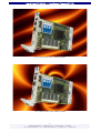
User Guide
CC3-CAJUN • CompactPCI ® Low Power CPU
Document No. 4015 • Edition 2
2005-12
User Guide CC3-CAJUN • Low Power CompactPCI CPU
Contents
About this Manual . . . . . . . . . . . . . . . . . . . . . . . . . . . . . . . . . . . . . . . . . . . . . . . . . . . . . . .
Edition History . . . . . . . . . . . . . . . . . . . . . . . . . . . . . . . . . . . . . . . . . . . . . . . . . . . . .
Related Documents . . . . . . . . . . . . . . . . . . . . . . . . . . . . . . . . . . . . . . . . . . . . . . . . .
Nomenclature . . . . . . . . . . . . . . . . . . . . . . . . . . . . . . . . . . . . . . . . . . . . . . . . . . . . .
Trade Marks . . . . . . . . . . . . . . . . . . . . . . . . . . . . . . . . . . . . . . . . . . . . . . . . . . . . . .
Legal Disclaimer - Liability Exclusion . . . . . . . . . . . . . . . . . . . . . . . . . . . . . . . . . . . . .
4
4
5
5
5
5
CC3-CAJUN Features . . . . . . . . . . . . . . . . . . . . . . . . . . . . . . . . . . . . . . . . . . . . . . . . . . . . . 6
Feature Summary . . . . . . . . . . . . . . . . . . . . . . . . . . . . . . . . . . . . . . . . . . . . . . . . . . 6
Short Description CC3-CAJUN . . . . . . . . . . . . . . . . . . . . . . . . . . . . . . . . . . . . . . . . . 9
Block Diagram CC3-CAJUN . . . . . . . . . . . . . . . . . . . . . . . . . . . . . . . . . . . . . . . . . . 10
Top View Component Assembly CC3-CAJUN . . . . . . . . . . . . . . . . . . . . . . . . . . . . . 11
Expansion Modules CC6-ACID & CC0-CHILLOUT . . . . . . . . . . . . . . . . . . . . . . . . . . 12
Rear I/O Transition Module CCY-RIO . . . . . . . . . . . . . . . . . . . . . . . . . . . . . . . . . . . 15
Rear I/O Transition Module CCZ-RIO . . . . . . . . . . . . . . . . . . . . . . . . . . . . . . . . . . . 17
Strapping Headers . . . . . . . . . . . . . . . . . . . . . . . . . . . . . . . . . . . . . . . . . . . . . . . . . 18
Connectors & Sockets . . . . . . . . . . . . . . . . . . . . . . . . . . . . . . . . . . . . . . . . . . . . . . 18
Front Panel Elements . . . . . . . . . . . . . . . . . . . . . . . . . . . . . . . . . . . . . . . . . . . . . . . 18
Microprocessor . . . . . . . . . . . . . . . . . . . . . . . . . . . . . . . . . . . . . . . . . . . . . .
Thermal Considerations . . . . . . . . . . . . . . . . . . . . . . . . . . . . . . . . . . . . . . . . . . . . .
Main Memory . . . . . . . . . . . . . . . . . . . . . . . . . . . . . . . . . . . . . . . . . . . . . . . . . . . .
LAN Subsystem . . . . . . . . . . . . . . . . . . . . . . . . . . . . . . . . . . . . . . . . . . . . . . . . . . .
Enhanced IDE / ATA Interface . . . . . . . . . . . . . . . . . . . . . . . . . . . . . . . . . . . . . . . .
Graphics Subsystem . . . . . . . . . . . . . . . . . . . . . . . . . . . . . . . . . . . . . . . . . . . . . . .
Real-Time Clock . . . . . . . . . . . . . . . . . . . . . . . . . . . . . . . . . . . . . . . . . . . . . . . . . . .
Universal Serial Bus (USB) . . . . . . . . . . . . . . . . . . . . . . . . . . . . . . . . . . . . . . . . . . .
RS-232E Serial Port . . . . . . . . . . . . . . . . . . . . . . . . . . . . . . . . . . . . . . . . . . . . . . . .
LPC Super- I/O Interface . . . . . . . . . . . . . . . . . . . . . . . . . . . . . . . . . . . . . . . . . . . . .
Watchdog/Reset . . . . . . . . . . . . . . . . . . . . . . . . . . . . . . . . . . . . . . . . . . . . . . . . . .
Firmware Hub (Flash BIOS) . . . . . . . . . . . . . . . . . . . . . . . . . . . . . . . . . . . . . . . . . .
ATA (Hard Disk Activity) LED . . . . . . . . . . . . . . . . . . . . . . . . . . . . . . . . . . . . . . . . .
GP (General Purpose) LED . . . . . . . . . . . . . . . . . . . . . . . . . . . . . . . . . . . . . . . . . . .
Hot Swap Detection . . . . . . . . . . . . . . . . . . . . . . . . . . . . . . . . . . . . . . . . . . . . . . .
Power Supply Status (DEG#, FAL#) . . . . . . . . . . . . . . . . . . . . . . . . . . . . . . . . . . . .
PXI Trigger Signals . . . . . . . . . . . . . . . . . . . . . . . . . . . . . . . . . . . . . . . . . . . . . . . . .
Local GPIO Option . . . . . . . . . . . . . . . . . . . . . . . . . . . . . . . . . . . . . . . . . . . . . . . . .
Rear I/O Options . . . . . . . . . . . . . . . . . . . . . . . . . . . . . . . . . . . . . . . . . . . . . . . . . .
19
20
22
22
23
24
25
25
25
26
27
27
28
28
28
28
28
29
30
Installing and Replacing Components . . . . . . . . . . . . . . . . . . . . . . . . . . . . . . . . . . . . . . . .
Before You Begin . . . . . . . . . . . . . . . . . . . . . . . . . . . . . . . . . . . . . . . . . . . . . . . . . .
Warnings . . . . . . . . . . . . . . . . . . . . . . . . . . . . . . . . . . . . . . . . . . . . . . . . . .
Caution . . . . . . . . . . . . . . . . . . . . . . . . . . . . . . . . . . . . . . . . . . . . . . . . . . .
Installing the Board . . . . . . . . . . . . . . . . . . . . . . . . . . . . . . . . . . . . . . . . . . . . . . . .
Removing the Board . . . . . . . . . . . . . . . . . . . . . . . . . . . . . . . . . . . . . . . . . . . . . . .
EMC Recommendations . . . . . . . . . . . . . . . . . . . . . . . . . . . . . . . . . . . . . . . . . . . . .
Installing or Replacing the Memory Module . . . . . . . . . . . . . . . . . . . . . . . . . . . . . .
Replacement of the Battery . . . . . . . . . . . . . . . . . . . . . . . . . . . . . . . . . . . . . . . . . .
31
31
31
31
32
33
34
35
35
-2EKF Elektronik GmbH • Philipp-Reis-Str. 4 • 59065 Hamm • Germany
Tel. +49 (0)2381/6890-0 • Fax. +49 (0)2381/6890-90 • [email protected] • www.ekf.com
User Guide CC3-CAJUN • Low Power CompactPCI CPU
Technical Reference . . . . . . . . . . . . . . . . . . . . . . . . . . . . . . . . . . . . . . . . . . . . . . . . . . . . .
Local PCI Devices . . . . . . . . . . . . . . . . . . . . . . . . . . . . . . . . . . . . . . . . . . . . . . . . . .
Local SMB Devices . . . . . . . . . . . . . . . . . . . . . . . . . . . . . . . . . . . . . . . . . . . . . . . . .
GPIO Usage . . . . . . . . . . . . . . . . . . . . . . . . . . . . . . . . . . . . . . . . . . . . . . . . . . . . . .
GPIO Usage ICH2 . . . . . . . . . . . . . . . . . . . . . . . . . . . . . . . . . . . . . . . . . . . .
GPIO Usage FWH . . . . . . . . . . . . . . . . . . . . . . . . . . . . . . . . . . . . . . . . . . . .
GPIO Usage SIO . . . . . . . . . . . . . . . . . . . . . . . . . . . . . . . . . . . . . . . . . . . . .
GPIO Usage PCI Bridge . . . . . . . . . . . . . . . . . . . . . . . . . . . . . . . . . . . . . . . .
Front Panel Connectors . . . . . . . . . . . . . . . . . . . . . . . . . . . . . . . . . . . . . . . . . . . . .
Video Monitor Connector DVI-I . . . . . . . . . . . . . . . . . . . . . . . . . . . . . . . . . .
Video Monitor Connector HD-DSUB (Option) . . . . . . . . . . . . . . . . . . . . . . .
USB Connector . . . . . . . . . . . . . . . . . . . . . . . . . . . . . . . . . . . . . . . . . . . . . .
Ethernet Connector . . . . . . . . . . . . . . . . . . . . . . . . . . . . . . . . . . . . . . . . . .
Serial I/F Connector RS-232 . . . . . . . . . . . . . . . . . . . . . . . . . . . . . . . . . . . . .
Internal Connectors . . . . . . . . . . . . . . . . . . . . . . . . . . . . . . . . . . . . . . . . . . . . . . . .
Caution . . . . . . . . . . . . . . . . . . . . . . . . . . . . . . . . . . . . . . . . . . . . . . . . . . .
LPC Low Pin Count Socket PLPC . . . . . . . . . . . . . . . . . . . . . . . . . . . . . . . . .
ATA/IDE Header . . . . . . . . . . . . . . . . . . . . . . . . . . . . . . . . . . . . . . . . . . . . .
Local GPIO Header (Option) . . . . . . . . . . . . . . . . . . . . . . . . . . . . . . . . . . . .
Speaker Header (Option) . . . . . . . . . . . . . . . . . . . . . . . . . . . . . . . . . . . . . . .
RTC/CMOS Reset Jumper (Option) . . . . . . . . . . . . . . . . . . . . . . . . . . . . . . . .
RS-232 Transceiver Enable Jumper (Option) . . . . . . . . . . . . . . . . . . . . . . . .
PLD Programming Header . . . . . . . . . . . . . . . . . . . . . . . . . . . . . . . . . . . . . .
Processor Debug Header . . . . . . . . . . . . . . . . . . . . . . . . . . . . . . . . . . . . . . .
CompactPCI J1/J2 . . . . . . . . . . . . . . . . . . . . . . . . . . . . . . . . . . . . . . . . . . . .
Power Connector P3 (Option) . . . . . . . . . . . . . . . . . . . . . . . . . . . . . . . . . . .
Literature . . . . . . . . . . . . . . . . . . . . . . . . . . . . . . . . . . . . . . . . . . . . . . . . . . . . . . .
-3EKF Elektronik GmbH • Philipp-Reis-Str. 4 • 59065 Hamm • Germany
Tel. +49 (0)2381/6890-0 • Fax. +49 (0)2381/6890-90 • [email protected] • www.ekf.com
36
36
36
37
37
38
38
39
40
41
42
43
43
44
46
46
47
48
49
49
49
50
50
51
52
55
56
User Guide CC3-CAJUN • Low Power CompactPCI CPU
About this Manual
This manual describes the technical aspects of the CC3-CAJUN, required for installation and
system integration. It is intended for the experienced user only.
Edition History
Document
Text # 4015
cc3_uge.wpd
Ed.
Contents/Changes
Author
Date
1
User Manual CC3-CAJUN, English, initial
edition
jj
15 November
2005
2
Photos added:
CC3 with DVI video output
CC3 with VGA video output
jj
21 December
2005
-4EKF Elektronik GmbH • Philipp-Reis-Str. 4 • 59065 Hamm • Germany
Tel. +49 (0)2381/6890-0 • Fax. +49 (0)2381/6890-90 • [email protected] • www.ekf.com
User Guide CC3-CAJUN • Low Power CompactPCI CPU
Related Documents
For information about the CC6-ACID refer to the CC6 Technical Information Manual, available
at http://www.ekf.de/c/ccpu/cc6/cc6.html.
For information about the CC0-CHILLOUT refer to the CC0 Technical Information Manual,
available at http://www/c/ccpu/cc6/cc6.html.
For information regarding the CCY-RIO rear I/O transition module please read the CCY Technical
Information Manual, available at http://www.ekf.de/c/ccpu/cc3/cc3_e.html.
For a description of the CC3-CAJUN BIOS see document 'CC3-CAJUN BIOS Quick Reference',
available by download at http://www.ekf.de/c/ccpu/cc3/cc3_e.html (document currently not yet
available).
For ordering information refer to document CC3-CAJUN Product Information, available at
http://www.ekf.de/c/ccpu/cc3/cc3_pie.pdf
Nomenclature
Signal names used herein with an attached '#' designate active low lines.
Trade Marks
Some terms used herein are property of their respective owners, e.g.
Intel, Pentium, Celeron, Tualatin, Coppermine: ® Intel
CompactPCI : ® PICMG
Windows 98, Windows NT, Windows 2000, Windows XP: ® Microsoft
EKF does not claim this list to be complete.
Legal Disclaimer - Liability Exclusion
This manual has been edited as carefully as possible. We apologize for any potential mistake.
Information provided herein is designated exclusively to the proficient user (system integrator,
engineer). EKF can accept no responsibility for any damage caused by the use of this manual.
-5EKF Elektronik GmbH • Philipp-Reis-Str. 4 • 59065 Hamm • Germany
Tel. +49 (0)2381/6890-0 • Fax. +49 (0)2381/6890-90 • [email protected] • www.ekf.com
User Guide CC3-CAJUN • Low Power CompactPCI CPU
CC3-CAJUN Features
Feature Summary
Feature Summary CC3-CAJUN
Form Factor
Single size CompactPCI style Eurocard (160x100mm2), front panel width 4HP (20.3mm)
Processor
Designed for Intel® ULV Celeron® and LV Pentium® III Micro FC-BGA processors (Tualatin 0.13µ
generation), maximum junction temperature 100°C, processor thermal design power classification:
<
<
<
<
CC3-1: 400MHz ULV Celeron, 0.95V, 100MHz FSB, 256KB L2 cache, 3.4W typical 4.2W max.
CC3-2: 650MHz ULV Celeron, 1.10V, 100MHz FSB, 256KB L2 cache, 7.0W typical 8.3W max.
CC3-3: 800MHz LV Pentium 3, 1.15V, 133MHz FSB, 512KB L2 cache, 11.2W max.
CC3-4: 933MHz LV Pentium 3, 1.15V, 133MHz FSB, 512KB L2 cache, 12.2W max.
Chipset
Intel® i815 chipset consisting of:
<
82815 Graphics/Memory Controller Hub (GMCH)
<
82801 I/O Controller Hub (ICH2)
<
82802 compatible Firmware Hub (FWH)
<
8761 LPC Super I/O
Memory
<
<
<
144-pin SO-DIMM socket
Support for up to 512MB, PC133, non ECC, unbuffered SDRAM
Support for serial presence detect (SPD) SO-DIMMs
Video
<
Both analog monitor and digital flat-panel display support by DVI-I connector (front panel), up
to 1280x1024 pixel 16M colors 85Hz refresh rate, incorporates PanelLink Digital technology
(Silicon Image)
Option: D-SUB (female HD15) connector available, replaces DVI-I connector
<
USB
Ports over-current protected, data transfer rate of up to 12Mbps, conforming to USB1.1
<
USB port 1: Type A connector (front panel)
<
USB port 2: J2/P2 Rear I/O option
Ethernet
10/100Mbps Fast Ethernet controller, 82551ER chip, RJ45 front panel connector
Serial Port
COM1
<
<
Legacy I/O
On-board RS-232E transceiver, RJ45 front panel connector (adapter RJ45 to D-Sub available),
transceiver can be disabled if rear I/O COM port option is preferred
J2/P2 Rear I/O option (TTL voltage level)
<
LPC Super-I/O interface connector, CC6-ACID mezzanine companion board available for top
(right) or bottom (left) mounting
J2/P2 Rear I/O option: Keyboard, Mouse, COM1 (TTL voltage level)
IDE/ATA
<
<
<
Ultra ATA/66 40-pin connector (primary IDE)
CompactFlash socket for CFA ATA cards (secondary IDE)
J2/P2 Rear I/O option: Primary IDE
CompactPCI
32-bit, 33.3MHz, PCI bridge chip PLX 6150, 133MByte/s CPCI master
J2/P2 Rear I/O
Option
<
<
<
<
<
PXI Support
TRIG0, TRIG1, TRIG6, TRIG7 (can be alternatively used as GPIO)
BIOS
<
<
<
Phoenix BIOS with EKF embedded systems enhancements
8Mbit Flash memory
Updates available from website ekf.com
Drivers
(Major OS)
<
<
Intel graphics drivers
Intel networking drivers
Power
Requirements
<
<
CC3-1-CAJUN: +5V±0.25V 1.3A max.+3.3V±0.1V 1.1A max.
CC3-2-CAJUN: +5V±0.25V 1.9A max.+3.3V±0.1V 1.3A max.
<
Primary IDE
USB port 2
PS/2 keyboard, mouse
COM1 (TTL voltage level)
Rear I/O transition module CCY-RIO available
-6EKF Elektronik GmbH • Philipp-Reis-Str. 4 • 59065 Hamm • Germany
Tel. +49 (0)2381/6890-0 • Fax. +49 (0)2381/6890-90 • [email protected] • www.ekf.com
User Guide CC3-CAJUN • Low Power CompactPCI CPU
Thermal
Conditions
Processor cooled down by passive heatsink, typical thermal resistance 13.8K/W (natural convection),
4.6K/W (forced airflow @ 200LFM). Custom specific heatsink solutions on request. Maximum ambient
operating temperature with standard heatsink:
<
<
<
<
*
CC3-1: 0-40°C (natural convection cooling), 0-70°C * (200LFM forced airflow)
CC3-2: 0-60°C (200LFM forced airflow), 0-70°C * (400LFM)
CC3-3: 0-45°C (200LFM forced airflow), 0-65°C (400LFM), 0-70°C * (600LFM)
CC3-4 0-40°C (200LFM forced airflow), 0-65°C (400LFM), 0-70°C * (600LFM)
Limited to 70°C due to other components than the processor
Environmental
Conditions
<
<
<
<
<
Storage temperature: -40°C ... +85°C, max. gradient 5°C/min
Humidity 5% ... 95% RH non condensing
Altitude -300m ... +3000m
Shock 15g 0.33ms, 6g 6ms
Vibration 1g 5-2000Hz
EC Regulations
<
<
EN55022, EN55024, EN60950-1 (UL60950-1/IEC60950-1)
2002/95/EC (RoHS)
MTBF
0.113 * 106h
Typical
Calculating
Performance
PCMark2002 under Windows 2000, CPU/MEM Score
1274/886 @400MHz
1990/933 @650MHz
tbd @800MHz
2854/1467 @933MHz
Subject to technical changes
-7EKF Elektronik GmbH • Philipp-Reis-Str. 4 • 59065 Hamm • Germany
Tel. +49 (0)2381/6890-0 • Fax. +49 (0)2381/6890-90 • [email protected] • www.ekf.com
User Guide CC3-CAJUN • Low Power CompactPCI CPU
CC3-CAJUN with DVI-I Video Output
CC3-CAJUN with VGA Video Output
-8EKF Elektronik GmbH • Philipp-Reis-Str. 4 • 59065 Hamm • Germany
Tel. +49 (0)2381/6890-0 • Fax. +49 (0)2381/6890-90 • [email protected] • www.ekf.com
User Guide CC3-CAJUN • Low Power CompactPCI CPU
Short Description CC3-CAJUN
Alternatively equipped with the Intel® series
of ULV Celeron® or LV Pentium® III
processors, the CC3-CAJUN is a versatile
4HP/3U (single size Eurocard) CompactPCI®
CPU board, designed especially for systems
which require very low power consumption.
Available either with the 400/650MHz Ultra
Low Voltage Celeron or 800/933MHz Low
Voltage Pentium III processor and up to
512MB RAM, the CC3-CAJUN covers a wide
range of applications, including PXI systems.
The DVI-I video interface is suitable for
attachment of both, advanced (digital) and
legacy (analog) displays (D-SUB connector
optionally available). The CC3-CAJUN is
provided with a 100Mbps Ethernet
controller. The on-board CompactFlash
socket allows for utilization of a CF card or
IBM Microdrive®. A local expansion interface
connector may be used to directly attach a
companion I/O board, which can carry in
addition a hard disk drive. As an option, rear
I/O across the J2/P2 connector is available.
photo soon here
-9EKF Elektronik GmbH • Philipp-Reis-Str. 4 • 59065 Hamm • Germany
Tel. +49 (0)2381/6890-0 • Fax. +49 (0)2381/6890-90 • [email protected] • www.ekf.com
User Guide CC3-CAJUN • Low Power CompactPCI CPU
Block Diagram CC3-CAJUN
ULV Celeron
400/650MHz
Block Diagram
CC3-CAJUN
LV Pentium 3
800/933MHz
SDRAM
64-512MB
PC100/133
Digital/Analog
DVI-I
164
GMCH
82815
SO-DIMM 144
Video
IDE I/F
VGA
D-SUB
FSB
100/133MHz
ICH2
82801
Compact
FLASH
ATA
Opt. Rear I/O (CCY-RIO)
IDE
USB
USB
EIA-232E
ADM
211
J-COM
COM (TTL)
87
61
KB/MS
LPC
RS-232
PCI
RJ45
COM
SIO
PXI Trig
GPIO
Front Panel I/O
RJ45
ETH
82
551
82
802
100Mbit
Ethernet
PCI Bridge
61
50
LPC
Expansion Board
Option
Low Pin Count
I/F
CompactPCI
FWH
J1
CC6-ACID / CC0-CHILLOUT
- 10 EKF Elektronik GmbH • Philipp-Reis-Str. 4 • 59065 Hamm • Germany
Tel. +49 (0)2381/6890-0 • Fax. +49 (0)2381/6890-90 • [email protected] • www.ekf.com
User Guide CC3-CAJUN • Low Power CompactPCI CPU
Top View Component Assembly CC3-CAJUN
PGPIO
PIDE
Compact
Flash
USB
COM
ETH
P3
JRTC
82
551
ICH2
CPU
RST
815
GMCH
DVI-I
or
VGA
JCOM
PLPC
61
50
SO-DIMM
PSPK
JSWAP
©EKF
CC3-CAJUN
ekf.com
- 11 EKF Elektronik GmbH • Philipp-Reis-Str. 4 • 59065 Hamm • Germany
Tel. +49 (0)2381/6890-0 • Fax. +49 (0)2381/6890-90 • [email protected] • www.ekf.com
User Guide CC3-CAJUN • Low Power CompactPCI CPU
Expansion Modules CC6-ACID & CC0-CHILLOUT
Available optionally as a mezzanine
companion board to the CC3-CAJUN, the
CC6-ACID is provided with several legacy I/O
ports in addition. This module can be
mounted either to the bottom side or on top
of the CC3-CAJUN and communicates across
the LPC (Low Pin Count) interface.
In addition, the CC6-ACID can be delivered
with an on-board 2.5-inch Ultra ATA hard
disk drive, resulting in a very compact
system. Both COM connectors, LPT, and PS/2
mouse and keyboard are situated at the CC6ACID front panel (4HP and 8HP versions
available).
The CC6-ACID could be useful if the classical
interfaces, e.g. serial and parallel ports, are
required by a given application.
The CC0-CHILLOUT is similar to the CC6ACID, but designated for use together with a
rear I/O transition module (CCZ-RIO).
Bus
Switch
40
IDE
IDE
CC2
CC3
44
EN
Optional On-Board
Ultra ATA/66
2.5" Hard Disk Drive
JSEL
FDD
LPT
LPT/Mouse
CC6-1 only
external
Floppy-Disk
(splitter cable
required for
CC6-3)
(Low Pin Count)
+5V
+3.3V
Super I/O
usage
optional
LPC
LPC
47B272
CompactPCI J1
K
CC6
-3
CC2
CC3
Block Diagram
CC6-ACID
COM
COM
Front Panel Connectors
CC6-1
JM
© EKF
ekf.com
FAN1..4 P6..P9
optional
MIDI/Gameport P10
optional
- 12 EKF Elektronik GmbH • Philipp-Reis-Str. 4 • 59065 Hamm • Germany
Tel. +49 (0)2381/6890-0 • Fax. +49 (0)2381/6890-90 • [email protected] • www.ekf.com
User Guide CC3-CAJUN • Low Power CompactPCI CPU
CC6-ACID (4HP)
CC6-ACID (8HP)
- 13 EKF Elektronik GmbH • Philipp-Reis-Str. 4 • 59065 Hamm • Germany
Tel. +49 (0)2381/6890-0 • Fax. +49 (0)2381/6890-90 • [email protected] • www.ekf.com
LPC
(Low Pin Count)
Super I/O
LPCT (Top Mounting)
LPCB (Bottom Mounting)
FDD P12
CC2
CC5
CC7
CC8
FDD P4/5
LPC P1
User Guide CC3-CAJUN • Low Power CompactPCI CPU
34
26
P10
external
Floppy-Disk
FD
FAN
P6-P9
IRDA
KB/MS
Game
GPIO
LPT
J1
Spkr
ADM
811
COM1
RS-232E
SD
Block Diagram
CC0-CHILLOUT
SD
J-SER1
Option
© EKF
SER1
Option
ADM
811
Rear I/O J2
MIDI
P11
TTL
COM2
RS-232E
SER2
TTL
USB1
J-SER2
USB1
CC2
CC5
CC7
Option
40
IDE1
EN
44
IDE2
Optional On-Board
Ultra ATA 2.5-"
Hard Disk Drive
IDE
Game
Super I/O
CC2
CC5
CC7
RJ45
RJ45
CC2
CC5
CC7
DVI-I
J-IDE2
DVI
Option
CC0-CHILLOUT Block Diagram
- 14 EKF Elektronik GmbH • Philipp-Reis-Str. 4 • 59065 Hamm • Germany
Tel. +49 (0)2381/6890-0 • Fax. +49 (0)2381/6890-90 • [email protected] • www.ekf.com
Rear I/O J1
CC2
CC5
CC7
Super I/O
Primary IDE P3
Primary IDE P2
KB/MS
Bus
Switch
User Guide CC3-CAJUN • Low Power CompactPCI CPU
Rear I/O Transition Module CCY-RIO
The CCY-RIO transition module provides a
4HP back panel with connectors for PS/2
style keyboard and mouse, a serial RS-232E
COM port, and an USB receptacle.
Rear I/O requires that a suitable J2 backplane
is present in your CompactPCI system. By
default, the CC3-CAJUN is equipped with line
terminating resistors for a common 64-bit
CPCI J2 backplane.
In addition, optional on-board headers are
provided on the CCY-RIO for internal
attachment of IDE/ATA devices (hard disks,
optical drives).
USB2
Available as a stuffing option, the CC3CAJUN can be delivered for rear I/O
utilization. Several I/O ports can be routed
across the J2 connector.
Block Diagram
CCY-RIO
Rear I/O
COM (TTL)
J2
IDE
ADM
211
COM (RS-232)
J-COM
KB/MS
MS
GPIO
PGPIO
PIDE1
PIDE2
KB
MS
J-IDE
- 15 EKF Elektronik GmbH • Philipp-Reis-Str. 4 • 59065 Hamm • Germany
Tel. +49 (0)2381/6890-0 • Fax. +49 (0)2381/6890-90 • [email protected] • www.ekf.com
Back Panel I/O
QS
16
245
IDE 44
GPIO13
IDE 40
CC2-TANGO
CC3-CAJUN
Rear I/O
USB2
COM
H1
EIA-232E
User Guide CC3-CAJUN • Low Power CompactPCI CPU
photo CC3-CAJUN & CCY-RIO soon here
CCY-RIO
- 16 EKF Elektronik GmbH • Philipp-Reis-Str. 4 • 59065 Hamm • Germany
Tel. +49 (0)2381/6890-0 • Fax. +49 (0)2381/6890-90 • [email protected] • www.ekf.com
User Guide CC3-CAJUN • Low Power CompactPCI CPU
Rear I/O Transition Module CCZ-RIO
Available as an option, the CC3-CAJUN can
be combined with the CC0-CHILLOUT
companion board, which has been designed
mainly for rear I/O systems. Therefore the
CCZ-RIO is required in addition for passing
signals across a single slot rear I/O backplane
to the rear panel.
GPIO (J1)
J1
Floppy 34
GPIO (J2)
The CCZ-RIO rear I/O transition module
provides a 4HP back panel (8HP option) with
connectors for PS/2 style keyboard and
mouse, an USB receptacle and optionally
Ethernet and video connectors. In addition,
optional on-board headers are stuffed on the
CCZ-RIO for attachment of various devices.
Floppy Disk I/F
Rear Panel COM2
Optional Flat Cable
Rear Panel COM1
Optional Flat Cable
Serial-1 (TTL)
4HP
Rear Panel
I/O
RS-232-1 (COM1)
Option 8HP
Rear Panel
I/O
Serial-2 (TTL)
COM2
J2 Rear I/O
Rear I/O Connector
CC0-CHILLOUT
CCA-LAMBADA
CCB-BOSSANOVA
RS-232-2 (COM2)
Block Diagram
CCZ-RIO
USB
USB
Speaker
Parallel Printer
Fan Control, IRDA I/O
RS-232-2 (J2)
Optional Flat Cable
MIDI
USB
Game
ETH
USB (CCB-BOSSANOVA)
MS
Ethernet (available with CC0-CHILLOUT and CCB-BOSSANOVA as an option)
KB
MS
VGA
PS/2 Keyboard/Mouse
DVI-I Digital & Analog Video (available with CC0-CHILLOUT as an option)
RS-232-1 (J2)
Optional Flat Cable
GPIO (J1)
GPIO Connector
COM1
J1 Rear I/O
Rear I/O Connector
CC0-CHILLOUT
CCA-LAMBADA
CCB-BOSSANOVA
Reset, Key Lock
IDE/ATA I/F (Secondary IDE)
PWR
+5V
- 17 EKF Elektronik GmbH • Philipp-Reis-Str. 4 • 59065 Hamm • Germany
Tel. +49 (0)2381/6890-0 • Fax. +49 (0)2381/6890-90 • [email protected] • www.ekf.com
User Guide CC3-CAJUN • Low Power CompactPCI CPU
Strapping Headers
ISPCON
In System Programmable GAL (PLD programming), not stuffed
JCOM
Local RS-232 transceiver enable, option
JRTC
CMOS and RTC reset
PGPIO
Local GPIO signals derived from the on-board SIO, option
PSPK
Speaker connector, option
Connectors & Sockets
CFA
CompactFlash ATA socket (secondary IDE interface)
J1/J2
CompactPCI Bus, PXI, Rear I/O
JSWAP
Signal from the board ejector lever switch, used for reset if dedicated push-button
is not present (all board versions with DVI connector)
P3
Power connector for stand-alone operation, not stuffed
PIDE
Ultra ATA/100 connector (primary IDE interface)
PITP
CPU Debug Port, not stuffed
PLPCT
PLPCB
Low Pin Count expansion interface connector (Super-I/O), available either from top
(T) or bottom (B) of the board
SODIMM
144-pin memory module SDRAM PC133
Front Panel Elements
Connector
Ethernet
100Base-TX/10Base-T, RJ45 receptacle with integrated indicator LEDs
Connector
Graphics
<
<
DVI-I integrated (digital & analog) receptacle, suitable for DVI digital flat
panel displays and/or analog monitors (standard solution)
D-Sub (HD 15-position female) VGA output (stuffing option)
Connector
RS-232E
Asynchronous serial interface (COM port), RJ45 jack (do not confuse with Ethernet
connector)
Connector
USB
Universal Serial Bus 1.1 self powered root hub, type A receptacle
LED ATA
LED indicating ATA/IDE activity
LED GP
Special purpose LED driven by GP output
LED POW
LED power good, stuffed if reset push-button with integrated LED is absent
Reset by
Push-button
Push-button switch with integrated indicator LED (power good), available with
D-Sub video connector option only
Reset by
Ejector Switch
Activating the ejector lever switch generates a CPU reset (if dedicated reset pushbutton is absent)
- 18 EKF Elektronik GmbH • Philipp-Reis-Str. 4 • 59065 Hamm • Germany
Tel. +49 (0)2381/6890-0 • Fax. +49 (0)2381/6890-90 • [email protected] • www.ekf.com
User Guide CC3-CAJUN • Low Power CompactPCI CPU
Microprocessor
The CC3-CAJUN supports the 0.13µ Ultra Low-Voltage (ULV) Celeron® and Low-Voltage (LV)
Pentium®-III processors as listed below. The processors are housed in a Micro FC-BGA package
for direct soldering to the PCB, i.e. the CPU chip cannot be removed or changed by the user.
Do not confuse the processor host bus frequency (FSB front side bus or PSB processor side bus)
with the memory speed or the PCI clock, which are independent from each other. The ULV
Celeron processors support 100MHz FSB clock, while the LV Pentium III processors are designed
for 133MHz FSB clock. The internal CPU speed is achieved by multiplying the host bus frequency
by a fixed value.
The CC3-CAJUN is powered across the CompactPCI connectors J1 (3.3V, 5V). The processor core
voltage is generated by a switched voltage regulator, sourced from the 5V plane. The ULV
Celeron processors signal their required core voltage by 5 dedicated pins according to the IMVPII
specification, which can be directly used to control the settings of the voltage regulator. The
required core voltage for the LV Pentium III processors however, complying to the VRM8.5
specification, must be adjusted by a couple of resistors on the CC3-CAJUN. The core voltage
settings actually in use can also be read back by several GPI lines of the ICH2.
ULV Celeron® 0.13µ Processors Supported (Pb Free RoHS compliant)
Processor
Speed
Host Bus
L2 Cache
CPU ID
Package
Stepping
sSpec
Celeron
400MHz
100MHz
256KB
06b1h
µFCBGA
FBA1
SL7UK
Celeron
650MHz
100MHz
256KB
06b4h
µFCBGA
FBB1
SL7UJ
Low Voltage Pentium® III 0.13µ Processors Supported (Pb Free RoHS compliant)
Processor
Speed
Host Bus
L2 Cache
CPU ID
Package
Stepping
sSpec
Pentium III
800MHz
133MHz
512KB
06b4h
µFCBGA
tB1
SL7T4
Pentium III
933MHz
133MHz
512KB
06b4h
µFCBGA
tB1
SL7T3
- 19 EKF Elektronik GmbH • Philipp-Reis-Str. 4 • 59065 Hamm • Germany
Tel. +49 (0)2381/6890-0 • Fax. +49 (0)2381/6890-90 • [email protected] • www.ekf.com
User Guide CC3-CAJUN • Low Power CompactPCI CPU
Thermal Considerations
In order to avoid malfunctioning of the CC3-CAJUN, take care of appropriate cooling of the
processor and system, e.g. by a cooling fan suitable to the maximum power consumption of the
CPU chip actually in use. Please note, that the processors temperature is steadily measured by a
special controller (MAX1617), attached to the onboard SMBus® (System Management Bus). The
processor core (die) temperature is signalled by the forward voltage of a CPU integrated diode.
A second diode internal to the MAX1617 allows for acquisition of the boards surface
temperature. The programmable over-temperature alarm allows to trigger the SMBus alert line
in order to avoid overheating. A suitable software to display both, the die temperature, as well
as the board temperature, is MBM (Motherboard Monitor), which can be downloaded from the
web. After installation, both temperatures can be observed permanently from the Windows
system tray.
By default, the CC3-CAJUN is equipped with a passive heatsink. Its height takes into account the
4HP limitation in mounting space of a CPCI board. In addition, a forced vertical airflow through
the system enclosure (e.g. bottom mount fan unit) is strongly recommended (>15m3/h or
200LFM around the CPU slot). As an exception, the CC3-1-CAJUN (ULV Celeron 400MHz) can be
operated with natural convection only. Be sure to thoroughly discuss your actual cooling needs
with EKF. Generally, the faster the CPU speed the higher its power consumption. For higher
ambient temperatures, consider increasing the forced airflow to 400 or 600LFM. A nonstandard heatsink also could improve (lower) the thermal resistance between the die and the
environment (requires more than 4HP board pitch, depending from the heatsink in use).
The maximum power consumption and operating temperature of a particular processor can be
derived from the tables below. Fortunately, the power consumption is by far lower when
executing typical Windows or Linux tasks. The heat dissipation increases especially when
rendering software is executed, e.g. the Acrobat Distiller. EKF tests the CC3-CAJUN by running
a proprietary Intel tool for generating the maximum stress to the processor.
ULV Celeron® 0.13µ Processors Power Consumption and Die Temperature
Processor
Speed
Typ. Power
Max. Power
Die Temperature
Celeron
400MHz
3.40W
4.23W
0-100°C
Celeron
650MHz
7.00W
8.30W
0-100°C
LV Pentium® III 0.13µ Processors Power Consumption and Die Temperature
Processor
Speed
Pentium III
Pentium III
Typ. Power
Max. Power
Die Temperature
800MHz
11.2W
0-100°
933MHz
12.2W
0-100°
The CC3-CAJUN can be equipped with either a heatsink according to the option 2 described in
the Intel Thermal Design Guide, which must be fixed by four mounting fasteners, or a snap-on
heat spreader, which is fixed by a clip directly to the BGA.
- 20 EKF Elektronik GmbH • Philipp-Reis-Str. 4 • 59065 Hamm • Germany
Tel. +49 (0)2381/6890-0 • Fax. +49 (0)2381/6890-90 • [email protected] • www.ekf.com
User Guide CC3-CAJUN • Low Power CompactPCI CPU
The forced airflow thermal resistance of the snap-on heatsink is 4.6K/W @ 200lfm, 2.7K/W @
400lfm and 2.0K/W @ 600lfm. With no forced airflow (natural convection) the heat sink
thermal resistance is ~13.8K/W. With 100°C as maximum specified die temperature, the worst
case ambient temperatures for the CC3-CAJUN can be calculated a follows:
Maximum Permissible Ambient Temperature
Processor
Max. Power
0 LFM
200 LFM
400 LFM
600 LFM
ULV Celeron
400MHz
4.23W
41.5°C
80.5°C
88.5°C
91.5°C
ULV Celeron
650MHz
8.3W
-
61.5°C
77.5°C
83.0°C
LV Pentium
III 800MHz
11.2W
-
48.0°C
69.5°C
77.5°C
LV Pentium
III 933MHz
12.2W
-
43.5°C
67.0°C
75.0°C
Temperatures marked italic/grey:
Nominal values only, the board should not be operated permanently beyond 70°C
As it can be seen, natural convection cooling is an option for the CC3-1-CAJUN only, which is
equipped with the ULV Celeron 400MHz processor. Forced airflow cooling between 200lfm
(ULV Celeron) and 400lfm (LV Pentium III) is recommended for typical operation of the board.
A special method to reduce power consumption and therefore increasing the maximum ambient
temperature, is to force the processor into the 'Throttle Mode'. This is achieved by actuating the
'Stop Clock' input of the CPU, and can be activated through the BIOS settings. A Throttle Mode
of 50% e.g. means a duty cycle of 50% on the stop clock input. However, while saving a certain
amount in power consumption, the data throughput of the processor is also reduced.
- 21 EKF Elektronik GmbH • Philipp-Reis-Str. 4 • 59065 Hamm • Germany
Tel. +49 (0)2381/6890-0 • Fax. +49 (0)2381/6890-90 • [email protected] • www.ekf.com
User Guide CC3-CAJUN • Low Power CompactPCI CPU
Main Memory
The CC3-CAJUN is equipped with a socket for installing a single 144-pin SO-DIMM module.
Minimum common memory size is 128MB; maximum memory size is 512MB. Due to the video
requirements of the i815 chipset, the recommended minimum memory for the Windows 2000
and Windows XP operating systems is 256MB (some of the system memory is dedicated to the
graphics controller). The supported on-board memory is entirely chacheable. The memory
module is a unbuffered SD-RAM, PC133 style. The contents of the SPD Eeprom are displayed on
system start by the BIOS. The memory clock is 133MHz maximum, due to limitations of the
815GMCH (Graphics and Memory Controller Hub).
The GMCH is sometimes also referenced as 'Northbridge'. No special drivers are needed for the
memory controller portion of the GMCH - configuration is done by the BIOS (including the
Video BIOS) and the operating system.
LAN Subsystem
The CC3-CAJUN is equipped with the 82551ER 100Mbps Ethernet controller. Features include:
C
C
C
C
PCI bus mastering 32-bit, 33MHz
100Base-TX (Fast Ethernet, half- or full-duplex) and 10Base-T (Classic Ethernet) capability
using a single RJ45 connector
IEEE 802.3µ Auto-Negotiation for the fastest available connection
Jumperless configuration (complete software-configurable)
Two display LEDs integrated into the RJ-45 connector signal the LAN connection speed and the
LAN link and activity status.
The NIC (Networking Interface Controller) resides on the local PCI bus. Its MAC address (unique
hardware number, mostly represented by 12 hexadecimal characters) is stored in an EEPROM.
A label may be present on the board showing its MAC ID 1. You could also execute "ifconfig"
(Linux) or "ipconfig /all" (Windows) in order to call up the MAC ID.
The Intel Ethernet software and drivers for the 82551ER are available from Intel's World Wide
Web site for download.
1
EKF native MAC IDs start with 00:C0:88. A label, if present, may show the full physical address
as 2-D barcode (DataMatrix), and in addition the least 6 hex characters as human readable
letters.
- 22 EKF Elektronik GmbH • Philipp-Reis-Str. 4 • 59065 Hamm • Germany
Tel. +49 (0)2381/6890-0 • Fax. +49 (0)2381/6890-90 • [email protected] • www.ekf.com
User Guide CC3-CAJUN • Low Power CompactPCI CPU
Enhanced IDE / ATA Interface
The EIDE interface (also referenced as ATA or PATA = Parallel ATA) is responsible for the
exchange of information between the processor and peripheral mass storage devices such as
hard disks, ATA CompactFlash cards and optical drives. The interface supports:
C
C
C
Up to three ATA devices (2 IDE, 1 CompactFlash)
PIO Mode 3/4, Ultra ATA/33, Ultra ATA/66, Ultra ATA/100
Support for LS-120 drives
The primary IDE interface is routed to a standard 40-position header (2.54mm pitch), allowing
master and slave device attached to one common flat ribbon cable (use special 80-pin cabling
assembly for Ultra ATA/66 and Ultra ATA/100 operation).
The presence of an 80-pin cable at the primary IDE interface could be checked out by reading
the state of the GPI1 of the Firmware Hub (FWH). The ATA standard defines the signal
PDIAG-/CBLID- for identifying the cable. This line is routed to GPI1 of the FWH. A logical 1
signals a 40-pin, a logical 0 a 80-pin cable. See the ATA/ATAPI-6 specification (section 6.7 “Host
determination of cable type by detecting CBLID-“) for details.
As an alternate, the primary IDE port is optionally also available for rear I/O across the J2/P2
CompactPCI connector. The CTY-RIO rear I/O transition module is provided with both, a 40position header for 3.5-inch PATA hard disks and IDE optical drives, and a 44-position header
for 2.5-inch IDE hard disk drives.
The secondary IDE interface is routed to the on-board CompactFlash Card Adapter socket. Use
this connector to attach a CompactFlash ATA style silicon disk, whenever a hard disk is not
suitable for your system, or as an additional mass storage device, or even as the boot device.
The display LED 'ATA', situated in the front panel signals the disk activity status of the primary
IDE devices and also the CompactFlash slot. This LED is also software programmable. See the
section “Programmable LED” how to do this.
The IDE controller is integrated into the i82801 ICH2 (I/O Controller Hub 2). The ICH2 is
sometimes also referenced as 'Southbridge'. Ultra ATA IDE drivers may be downloaded from the
Intel website, but are already part of all popular operating systems.
- 23 EKF Elektronik GmbH • Philipp-Reis-Str. 4 • 59065 Hamm • Germany
Tel. +49 (0)2381/6890-0 • Fax. +49 (0)2381/6890-90 • [email protected] • www.ekf.com
User Guide CC3-CAJUN • Low Power CompactPCI CPU
Graphics Subsystem
The graphics subsystem is part of the Intel 82815 Graphics/Memory Controller Hub (GMCH),
supporting the following features:
C
C
C
C
C
C
C
C
3-D Hyper Pipelined architecture
Full 2-D hardware acceleration
Motion video acceleration
3-D graphics visual and texturing enhancements
Integrated 24-bit 230MHz RAMDAC
DDC2B compliant
Hardware motion compensation for software MPEG2 decode
Integrated graphics memory controller
The CC3-CAJUN is provided with the DVI-I graphics connector. This is both, a digital and analog
interface. Recent digital input flat-panel displays are widely available with this connector style
(e.g. the NEC Mitsubishi Ambix series, or the Samsung Syncmaster series 193T/213T/214T). For
classic monitors, adapters or adapter cables can be used for converting from DVI-I to the 15-pin
HD D-SUB connector.
A special display transmitter chip is used for serializing/deserializing the differential DVI signals.
The SiI164 (Silicon Image) transmitter uses PanelLink® Digital technology to support displays
ranging from VGA to UXGA resolutions (25 - 165Mpps) in a single link interface. The SiI164
transmitter has a highly flexible interface with 12-bit (½ pixel/clock) or 24-bit (1 pixel/clock)
input for true color (16.7 million) support. It can be foreseen, that DVI will overcome the legacy
analog and proprietary digital interfaces in the near future.
The GMCH supports several video resolutions and refresh rates. A partial list is contained in the
table below. Please note, that flat-panel displays should be operated with their maximum
resolution at 60Hz refresh rate.
i815 GMCH Video Modes and Clock Rates (Partial List)
Resolution/
Refresh Rate
60Hz
70Hz
72Hz
75Hz
85Hz
640x480
25.175MHz
28MHz
31.5MHz
31.5MHz
36MHz
800x600
40MHz
45MHz
50MHz
49.5MHz
56.25MHz
1024x768
65MHz
75MHz
-
78.75MHz
94.5MHz
1152x864
80MHz
96MHz
99MHz
108MHz
121MHz
1280x1024
108MHz
128.89MHz
132MHz
135MHz
157.5MHz
1600x1200
162MHz
189MHz
195MHz
202.5MHz
229.5MHz
Video modes marked italic/blue: Suitable for popular flat-panel displays
- 24 EKF Elektronik GmbH • Philipp-Reis-Str. 4 • 59065 Hamm • Germany
Tel. +49 (0)2381/6890-0 • Fax. +49 (0)2381/6890-90 • [email protected] • www.ekf.com
User Guide CC3-CAJUN • Low Power CompactPCI CPU
As a stuffing option, the CC3-CAJUN can be equipped with an ordinary HD D-Sub 15-lead
female connector (VGA style). This connector is suitable for analog signals only, so the PanelLink
transmitter is not stuffed with this option. Nevertheless also most flat-panel displays can be
attached to the D-Sub connector with only minor impact on the image quality.
Independent from the video connector actually in use, DVI or VGA, the VESA DDC 2B standard
is supported. This is a two-wire serial bus (clock, data), which is controlled by the GMCH and
allows to read out important parameters, e.g. the maximum allowable resolution, from the
attached monitor. In addition, DDC Power (+5V) is delivered to either connector. Resettable
fuses are stuffed to protect the board from an external short-circuit condition (0.75A for DVI, 2
x 0.75A for VGA).
Graphics drivers for the i815 GMCH can be downloaded from the Intel website, if required.
Real-Time Clock
The CC3-CAJUN has a time-of-day clock and 100-year calendar, integrated into the ICH2. A
battery on the board keeps the clock current when the computer is turned off. The CC3 uses a
Vanadium-Pentoxide-Lithium rechargeable battery, giving an autonomy of more than 80 days
when fully loaded after 24 hours. The cell is free of memory effects and withstands deep
discharging. Under normal conditions, replacement should be superfluous during lifetime of the
board. The RTC registers can be manually reset by the jumper JRTC.
Universal Serial Bus (USB)
The CC3-CAJUN is provided with two USB 1.1 ports. One USB I/F is routed to a front panel
connector, while the other is optionally available for rear I/O across the J2/P2 CompactPCI
connector. When using both ports, you can connect a maximum of two USB peripheral devices
directly to the CC3 without an external hub. To attach more devices, get an external hub
attached to one of the CC3 USB ports. Both, the front panel USB connector and the rear I/O USB
interface can source up to 0.5A/5V to external devices, over-current protected by an electronic
switch. Both USB controllers are integrated into the i82801 ICH2.
RS-232E Serial Port
The CC3-CAJUN is provided with an on-board EIA-232E compatible transceiver, connected to a
UART (universal asynchronous receiver transmitter), which is contained in the 8761 LPC I/O chip
(see next paragraph). The transceiver is ESD protected and supports a minimum data rate of
230kbps. Due to limited space in the front panel, a RJ45 jack is used for this COM port. An
adapter (available from EKF) may be helpful to emulate the PC-style 9-position D-Sub connector
(signal RI = Ring Indicator not supported). Usage of the RS-232 front panel connector requires
that the jumper J-COM on the CC3-CAJUN is set in order to enable the transceiver. However, if
rear I/O was chosen for the COM port, J-COM must be removed (instead enable the alternate
transceiver on the CCY-RIO rear I/O transition module).
- 25 EKF Elektronik GmbH • Philipp-Reis-Str. 4 • 59065 Hamm • Germany
Tel. +49 (0)2381/6890-0 • Fax. +49 (0)2381/6890-90 • [email protected] • www.ekf.com
User Guide CC3-CAJUN • Low Power CompactPCI CPU
LPC Super- I/O Interface
In a modern system, legacy ports as PS/2 keyboard/mouse, COM1/2 and LPT have been replaced
by USB and Ethernet connectivity. The 1.4MB floppy disk drive has been overcome by CD-RW or
DVD-RW optical drives, attached to the IDE connector, or USB memory sticks. Hence, the CC3CAJUN is virtually provided with all necessary I/O ports. However, for compatibility purposes the
CC3 is additionally equipped with a simple Super-I/O chip, for optional rear I/O of PS/2
keyboard/mouse and COM1 (TTL level only) across the J2/P2 CPCI connector. The Super-I/O
controller resides on the local LPC bus (LPC = Low Pin Count interface standard), which is a
serialized ISA bus replacement, controlled by the ICH2 hub.
As an alternative, EKF offers the CC6-ACID, an expansion module to the CC3-CAJUN, featuring
all classic Super-I/O functionality. The CC6-ACID is a 3U Eurocard, with an either 8HP (double)
or 4HP (single) width front panel. Access to the connectors COM1/2, LPT, mouse, keyboard is
given directly from the front panel. On board connectors are provided for FDD, MIDI/Gameport,
and cooling fans. Optionally, the CC6 is available with an on-board 2.5-inch hard disk drive. The
CC6-ACID connects to the CC3-CAJUN across the connectors PLPC and PIDE. The CC6-ACID can
be attached either to the top of the CC3-CAJUN or to the bottom (bottom attachment restricted
to the 4HP version of the CC6-ACID).
The photo above (left) shows the bottom attachment of the CC6-ACID. The boards are fixed
together by the LPC connector and the IDE connector, and in addition by a bracket which bolts
together both front panels. The right image shows the top attachment of the CC6-ACID.
The photo above (left) shows the CC3-CAJUN and CC6-ACID connected by the LPC interface. The
right image shows the front panel fixing bracket.
Together, the CC3-CAJUN and the CC6-ACID form an ultra-compact, complete desktop
functionality, industrial grade computer system.
- 26 EKF Elektronik GmbH • Philipp-Reis-Str. 4 • 59065 Hamm • Germany
Tel. +49 (0)2381/6890-0 • Fax. +49 (0)2381/6890-90 • [email protected] • www.ekf.com
User Guide CC3-CAJUN • Low Power CompactPCI CPU
Watchdog/Reset
The CC3-CAJUN is provided with two MAX6705 supervisor circuits, which monitor the supply
voltages 3.3V and 5V, and generate a power-on reset signal. The manual push-button reset is
also passed through the MAX6705s for appropriate pulse conditioning.
The reset push-button (if present) is situated at the front panel. The button is indent mounted
behind the front and requires a tool, e.g. pen to be pressed, preventing from being inadvertently
activated. Due to front panel space limitations, those versions of the CC3-CAJUN with a DVI
video connector do not provide a reset push-button, but have a switch integrated into the
board ejection lever. This switch is activated by pushing the red bolt on top of the ejector lever.
The manual reset signal is routed across a PLD (programmable logic device) and could be
passivated on customers request.
The healthy state of the CC3-CAJUN is signalled by the LED PWR, visible either through a small
slot in the front panel, or integrated into the reset push-button. As soon as this LED begins to
shine all power voltages are well and the reset signal has been deasserted.
Another feature is the watchdog function, which can be be programmed by software. The
behaviour of the MAX6705 watchdog is partially defined by the PLD, which controls whether
the watchdog is activated. The related software (e.g. BIOS, application program) must trigger
the watchdog by toggling the GPO21 signal of the ICH2.
The watchdog is in a passive state after a system reset. There is no need to trigger it at boot
time. Once the GPO21 of the ICH2 has sent a pulse, the watchdog is activated. If the duration
between two trigger pulses exceeds a period of 1000ms, the watchdog times out and a system
reset will be generated.
The watchdog remains in the active state until the next system reset. There is no way to disable
it once it was started.
Firmware Hub (Flash BIOS)
The BIOS is stored in a 82802 compatible 8Mbit Firmware Hub (there are second sources in use
with deviant part numbers). The firmware hub contains a nonvolatile memory core based on
flash technology, allowing the BIOS to be upgraded.
The FWH can be reprogrammed (if suitable) by a DOS based tool. This program and the latest
CC3-CAJUN BIOS are available from the EKF website. Read carefully the enclosed instructions. If
the programming procedure fails e.g caused by a power interruption, the CC3-CAJUN may no
more be operable. You would have to send in the board, because the BIOS is directly soldered
to the PCB and cannot be changed by the user.
- 27 EKF Elektronik GmbH • Philipp-Reis-Str. 4 • 59065 Hamm • Germany
Tel. +49 (0)2381/6890-0 • Fax. +49 (0)2381/6890-90 • [email protected] • www.ekf.com
User Guide CC3-CAJUN • Low Power CompactPCI CPU
ATA (Hard Disk Activity) LED
The CC3-CAJUN is provided with a software programmable LED in the front panel, labeled as
ATA. After system reset, this LED defaults to signal the ATA/IDE activity. By the first setting of the
GPO22 of the ICH2 82801 this LED changes its function and is then controlled only by the level
of the GPO22 pin. Setting this output to 1 will switch on the LED.
The LED IDE remains in the programmable state until the next system reset.
GP (General Purpose) LED
A second programmable LED can be also observed from the front panel. The status of the GP
LED is controlled by the GPO23 output of the ICH2. As of current, the GP LED is not dedicated
to any particular hardware or firmware function (this may change in the future). It is therefore
user programmable.
Hot Swap Detection
The CompactPCI specification added the signal ENUM# to the PCI bus to allow the system hot
swapping. This signal is routed to the GPI6 of the ICH2 82801 on the CC3-CAJUN. A System
Management Interrupt (SMI) can be requested if ENUM# changes by insertion or removal of a
board.
Note that the CC3-CAJUN itself isn’t a hot swap device, because it makes no sense to remove
the system controller from a CompactPCI system. However, it is capable to recognize the hot
swap of peripheral boards and to start software that is doing any necessary system
reconfiguration.
Power Supply Status (DEG#, FAL#)
Power supply failures may be detected before the system crashes down by monitoring the
signals DEG# or FAL#. These active low lines are additions of the CompactPCI specification and
may be driven by the power supply.
DEG# signals the degrading of the supply voltages, FAL# there possible failure.
On the CC3-CAJUN FAL# is routed to the GPI0 and DEG# to the GPI1 of the ICH2 82801.
PXI Trigger Signals
As an option, the CC3-CAJUN supports four of the eight trigger signals of the PXI standard, as
defined by National Instruments. The trigger signals are provided by the local SIO (Super-I/O)
chip. GPIO20/21 are routed to TRIG0/1, and GPIO26/27 are used to control TRIG6/7. These
signals can also be used as GPIO lines in a non-PXI environment.
- 28 EKF Elektronik GmbH • Philipp-Reis-Str. 4 • 59065 Hamm • Germany
Tel. +49 (0)2381/6890-0 • Fax. +49 (0)2381/6890-90 • [email protected] • www.ekf.com
User Guide CC3-CAJUN • Low Power CompactPCI CPU
Local GPIO Option
In addition to the GPIO / PXI-Trigger lines optionally available on J2, the optional pin-header
PGPIO provides another two GPIO lines available for user specific application. The 5V level TTL
signals sio_gpio16/17 are controlled by the on-board SIO IT8761E, with an internal 50k PU
resistor and capable of sinking 24mA each.
- 29 EKF Elektronik GmbH • Philipp-Reis-Str. 4 • 59065 Hamm • Germany
Tel. +49 (0)2381/6890-0 • Fax. +49 (0)2381/6890-90 • [email protected] • www.ekf.com
User Guide CC3-CAJUN • Low Power CompactPCI CPU
Rear I/O Options
Optionally, the CC3-CAJUN can be used for rear I/O with respect to the following functions:
•
•
•
•
•
Primary IDE
USB Port 2
Keyboard, Mouse
COM1 (TTL Level)
GPIOs
If attachment of IDE devices across the rear I/O path is chosen, the CC3-CAJUN on-board IDE
connector must be removed or at least left unused, in order to avoid a T-connection. The rear
I/O USB port is independent from the front panel USB connector by using its own controller
integrated into the ICH2, thus doubling the overall USB bandwidth available. Keyboard and
mouse as well as the serial interface and the GPIOs require the on-board SIO to be stuffed. The
rear I/O COM1 port does not include the physical transceiver (TTL level signals only), because the
CCY-RIO module is provided with its own circuitry - be sure to remove the jumper J-COM on the
CC3-CAJUN before enabling the serial interface transceiver on the rear I/O module. The GPIOs
are used as trigger signals in a PXI system, but can also be utilized for general applications in a
non-PXI environment. Each of the above functions can be activated individually (by appropriate
stuffing/removing of resistor networks).
Utilization of the CCY-RIO rear I/O transition module is bound to several preconditions, which
must be completely satisfied:
<
The CC3 CPU card by default is suitable for a 64-bit CompactPCI backplane. However, the
J2/P2 pin assignments of a 64-bit CPCI backplane differ substantially from a CompactPCI
rear I/O backplane. Hence usage of the rear I/O features is available only as stuffing
options on the CC3 CPU board, which have to be ordered explicitly. Pull-up resistor
networks on the CPCI address/data lines AD33-AD63 and associated control signals must
be removed, and pass-through resistor networks for the required rear I/O signals have to
be filled on the CC3. Neither can these modifications be made afterwards on a CC3 64bit J2 CPU board by the user, nor by EKF, due to the technical effort needed and costs
incurred.
<
The system in use must be equipped with a P2 CompactPCI rear I/O backplane. If the
system is provided with a P2 CompactPCI 64-bit backplane instead, several of the CC3
rear I/O signals will collide with the 64-bit address/data lines on the backplane, with
unpredictable results regarding the rear I/O signal integrity.
Please note, that EKF is not only a manufacturer of boards, but also has many years of
experience as a systems integrator. Please contact [email protected] for a quotation on the complete
system, tailored to your individual needs.
- 30 EKF Elektronik GmbH • Philipp-Reis-Str. 4 • 59065 Hamm • Germany
Tel. +49 (0)2381/6890-0 • Fax. +49 (0)2381/6890-90 • [email protected] • www.ekf.com
User Guide CC3-CAJUN • Low Power CompactPCI CPU
Installing and Replacing Components
Before You Begin
Warnings
The procedures in this chapter assume familiarity with the general terminology associated with
industrial electronics and with safety practices and regulatory compliance required for using and
modifying electronic equipment.
Disconnect the system from its power
source and from any telecommunication
lin ks, networks or m o d e m s b e f o r e
performing any of the procedures
described in this chapter. Failure to
disconnect power, or telecommunication
links before you open the system or
perform any procedures can result in
personal injury or equipment damage.
Some parts of the system can continue to operate even though the power switch is in its off
state.
Caution
Electrostatic discharge (ESD) can damage components. Perform the procedures described in this
chapter only at an ESD workstation. If
such a station is not available, you can
provide some ESD protection by wearing
an antistatic wrist strap and attaching it
to a metal part of the system chassis or
board front panel. Store the board only
in its original ESD protected packaging.
Retain the original packaging (antistatic
bag and antistatic box) in case of returning the board to EKF for rapair.
- 31 EKF Elektronik GmbH • Philipp-Reis-Str. 4 • 59065 Hamm • Germany
Tel. +49 (0)2381/6890-0 • Fax. +49 (0)2381/6890-90 • [email protected] • www.ekf.com
User Guide CC3-CAJUN • Low Power CompactPCI CPU
Installing the Board
Warning
This procedure should be done only by qualified technical personnel. Disconnect the system
from its power source before doing the procedures described here. Failure to disconnect power,
or telecommunication links before you open the system or perform any procedures can result in
personal injury or equipment damage.
Typically you will perform the following steps:
C
Switch off the system, remove the AC power cord
C
Attach your antistatic wrist strap to a metallic part of the system
C
Remove the board packaging, be sure to touch the board only at the front panel
C
Identify the related CompactPCI slot (peripheral slot for I/O boards, system slot for CPU
boards, with the system slot typically most right or most left to the backplane)
C
Unlock the ejector lever by pushing the red locking bolt, move downward the ejector
lever, insert card carefully between the slot guiding rails (be sure not to damage
components mounted on the bottom side of the board by scratching neighboured front
panels), and give a moderate final press to the front panel in order to match the boards
CPCI receptacle(s) with the backplane connector(s)
C
A card with additional on-board connectors requires attachment of associated cabling
now
C
Lock the ejector lever, fix screws at the front panel (top/bottom)
C
Retain the original packaging in case of return
- 32 EKF Elektronik GmbH • Philipp-Reis-Str. 4 • 59065 Hamm • Germany
Tel. +49 (0)2381/6890-0 • Fax. +49 (0)2381/6890-90 • [email protected] • www.ekf.com
User Guide CC3-CAJUN • Low Power CompactPCI CPU
Removing the Board
Warning
This procedure should be done only by qualified technical personnel. Disconnect the system
from its power source before doing the procedures described here. Failure to disconnect power,
or telecommunication links before you open the system or perform any procedures can result in
personal injury or equipment damage.
Typically you will perform the following steps:
C
Switch off the system, remove the AC power cord
C
Attach your antistatic wrist strap to a metallic part of the system
C
Identify the board, be sure to touch the board only at the front panel
C
Unfasten both front panel screws (top/bottom), unlock the ejector lever by pushing the
red locking bolt, move downward the ejector lever - the board glides some millimeters
out of the chassis now
C
Remove any potential on-board cabling assembly now
C
Remove the card carefully (be sure not to damage components mounted on the bottom
side of the board by scratching neighboured front panels)
C
Store board in the original packaging, do not touch any components, hold the board at
the front panel only
Warning
Do not expose the card to fire. Battery cells and other components could
explode and cause personal injury.
- 33 EKF Elektronik GmbH • Philipp-Reis-Str. 4 • 59065 Hamm • Germany
Tel. +49 (0)2381/6890-0 • Fax. +49 (0)2381/6890-90 • [email protected] • www.ekf.com
User Guide CC3-CAJUN • Low Power CompactPCI CPU
EMC Recommendations
In order to comply with the CE regulations for EMC, it is mandatory to observe the following
rules:
C
The chassis or rack including other boards in use must comply entirely with CE
C
Close all board slots not in use with a blind front panel
C
Front panels must be fastened by built-in screws
C
Cover any unused front panel mounted connector with a shielding cap
C
External communications cable assemblies must be shielded (shield connected only at
one end of the cable)
C
Use ferrite beads for cabling wherever appropriate
C
Some connectors may require additional isolating parts
Reccomended Accessories
Blind CPCI Front
Panels
EKF Elektronik
Widths currently available
(1HP=5.08mm):
with handle 4HP/8HP
without handle
2HP/4HP/8HP/10HP/12HP
Ferrit Bead Filters
ARP Datacom,
63115 Dietzenbach
Ordering No.
102 820 (cable diameter 6.5mm)
102 821 (cable diameter 10.0mm)
102 822 (cable diameter 13.0mm)
Metal Shielding
Caps
Conec-Polytronic,
59557 Lippstadt
Ordering No.
CDFA 09 165 X 13129 X (DB9)
CDSFA 15 165 X 12979 X (DB15)
CDSFA 25 165 X 12989 X (DB25)
- 34 EKF Elektronik GmbH • Philipp-Reis-Str. 4 • 59065 Hamm • Germany
Tel. +49 (0)2381/6890-0 • Fax. +49 (0)2381/6890-90 • [email protected] • www.ekf.com
User Guide CC3-CAJUN • Low Power CompactPCI CPU
Installing or Replacing the Memory Module
Note: If you decide to replace the memory, observe the precautions in 'Before You Begin'
By default, the CC3-CAJUN comes fully equipped and tested with a 256MB/512MB SD-RAM
memory module. So normally there should be no need to install a memory module.
The CC3-CAJUN requires a PC-133 (133MHz) SDRAM SO-DIMM module independent from the
processor front side bus (100MHz ULV Celeron, 133MHz LV Pentium III). It is highly
recommended that Serial Presence Detect (SPD) SO-DIMMs be used, since this allows the chipset
to accurately configure the memory settings for optimum performance. If non-SPD memory is
installed, the BIOS will attempt to correctly configure the memory settings, but performance and
reliability may be impacted.
A replacement memory module must match the 144-pin SO-DIMM form factor (known from
Notebook PCs), 3.3V, 133MHz unbuffered, non-ECC style. Be sure to buy no module with a
height >1.250 inch (31.75mm). Suitable modules are available up to 512MB. The 815GMCH
supports modules of up to a maximum of 13 address lines (A0...A12). Memory modules
organized by more than13 address lines are not suitable.
Replacement of the Battery
When your system is turned off, a Vanadium Pentoxide Lithium rechargeable battery maintains
the current time-of-day clock and keeps the values contained in the CMOS RAM valid for a
couple of weeks. It is normal behaviour that the battery may be fully discharged, due to storage
time or after longer system down period. The battery is rechargeable approx. 1,000 times at
10% discharge depth to nominal capacity and should last during the lifetime of the CC3-CAJUN.
For replacement, the old battery must be desoldered, and the new one soldered (Panasonic
VL1220). Observe the cell polarization. We suggest that you send back the board to EKF for
battery replacement.
Warning
Danger of explosion if the battery is incorrectly replaced. Replace only with the
same or equivalent type. Do not expose a battery to fire.
- 35 EKF Elektronik GmbH • Philipp-Reis-Str. 4 • 59065 Hamm • Germany
Tel. +49 (0)2381/6890-0 • Fax. +49 (0)2381/6890-90 • [email protected] • www.ekf.com
User Guide CC3-CAJUN • Low Power CompactPCI CPU
Technical Reference
Local PCI Devices
The following table shows the on-board PCI devices and their location within the PCI
configuration space. These devices consist of the Ethernet controller, the PCI-To-PCI Bridge and
several devices within the i815 chip set.
Bus
Number
Device
Number
Function
Number
Vendor ID
Device ID
Description
0
0x00
0
0x8086
0x7120
Host Bridge
0
0x01
0
0x8086
0x7121
VGA Display
0
0x1E
0
0x8086
0x2418
PCI-To-PCI Bridge
0
0x1F
0
0x8086
0x2410
ISA Bridge
0
0x1F
1
0x8086
0x2411
IDE Controller
0
0x1F
2
0x8086
0x2412
USB Controller
0
0x1F
3
0x8086
0x2413
SMB Controller
1
0x04
0
0x8086
0x1209
Ethernet Controller
1
0x06
0
0x104C
0xAC28
PCI-To-PCI Bridge (CPCI)
Local SMB Devices
The CC3-CAJUN contains a few devices that are reachable via the System Management Bus
(SMB). These are the clock generation chip, the SPD EEPROM on the SO-DIMM memory module
and a CPU temperature controlling device in particular. Other devices could be connected to the
SMB via the CompactPCI signals IPMB SCL (J1 B17) and IPMB SDA (J1 C17).
Address
Description
0x30
CPU Temperature Sensor MAX 1617
0xA0
SPD of SO-DIMM
0xD2
Main Clock Generation ICS 9250-16
0xA4
Board EEPROM 24C04
- 36 EKF Elektronik GmbH • Philipp-Reis-Str. 4 • 59065 Hamm • Germany
Tel. +49 (0)2381/6890-0 • Fax. +49 (0)2381/6890-90 • [email protected] • www.ekf.com
User Guide CC3-CAJUN • Low Power CompactPCI CPU
GPIO Usage
GPIO Usage ICH2
CC3-CAJUN GPIO Usage ICH2
Function
CC3
Features
Origin/Destination
p2_fal#
GPI 0 ICH2
I (5V tol.)
CPCI Power Mgmt.
p2_deg#
GPI 1 ICH2
I (5V tol.)
CPCI Power Mgmt.
pirqe#
GPI 2 ICH2
I
LAN NC1
pirqf#
GPI 3 ICH2
(5V tol.)
CPCI INTC#
pirqg#
GPI 4 ICH2
(5V tol.)
CPCI INTD#
pirqh#
GPI 5 ICH2
I
ICH2 USB2
p1_enum#
GPI 6 ICH2
I (5V tol.)
CPCI
-
GPI 7 ICH2
I (5V tol.)
-
Vid4
GPI 8 ICH2
I
Core Voltage Regulator (read only)
-
intruder#
I
-
smbalrt#
GPI 11 ICH2
I
SMB
lsmi# (LPC)
GPI 12 ICH2
I
SIO (LPC)
lpme# (LPC)
GPI 13 ICH2
I
SIO (LPC)
GPO 16 ICH2
O (int. PU)
p2_trg7
GPO 17 ICH2
O (int. PU)
-
GPO 18 ICH2
O
-
-
GPO 19 ICH2
O
-
-
GPO 20 ICH2
O
-
wdi#
GPO 21 ICH2
O
ispGAL
gpo22 (ispGAL)
GPO 22 ICH2
OD
ispGAL
gpo23 (ispGAL)
GPO 23 ICH2
O
ispGAL
Vid0
GPIO 24 ICH2
I/O
Core Voltage Regulator (r/w)
Vid1
GPIO 25 ICH2
I/O
Core Voltage Regulator (r/w)
Vid2
GPIO 27 ICH2
I/O
Core Voltage Regulator (r/w)
Vid3/4
GPIO 28 ICH2
I/O
Core Voltage Regulator (r/w)
- 37 EKF Elektronik GmbH • Philipp-Reis-Str. 4 • 59065 Hamm • Germany
Tel. +49 (0)2381/6890-0 • Fax. +49 (0)2381/6890-90 • [email protected] • www.ekf.com
User Guide CC3-CAJUN • Low Power CompactPCI CPU
GPIO Usage FWH
CC3-CAJUN GPIO Usage FWH
Function
FWH
Features
Origin/Destination
FWH1/FWH2 Identity
GPI 0 FWH
I (3.3V)
GND = FWH1
3.3V = FWH2
p66detect (IDE)
GPI 1 FWH
I (3.3V)
IDE I/F
wdogrst
GPI 2 FWH
I (3.3V)
ispGAL
MSB Board Revision
GPI 3 FWH
I (3.3V)
LSB Board Revision
GPI 4 FWH
I (3.3V)
GPI3 GPI4 Rev.
0
0
0
0
1
1
1
0
2
1
1
3+
GPIO Usage SIO
CC3-CAJUN GPIO Usage SIO
Function
SIO
Features
Origin/Destination
p2_brsva15
GPIO 13 SIO
I/O (5V int. PU 8mA)
Rear I/O Module
Detection J2/P2
-
GPIO 14 SIO
I/O (5V int. PU 8mA)
-
GPIO 15 SIO
I/O (5V int. PU 8mA)
sio_gpio16
GPIO 16 SIO
I/O (5V int. PU 24mA)
PGPIO
sio_gpio17
GPIO 17 SIO
I/O (5V int. PU 24mA)
PGPIO
p2_brsvb16
GPIO 20 SIO
I/O (5V int. PU 8mA)
PXI TRIG0 J2/P2
p2_brsva16
GPIO 21SIO
I/O (5V int. PU 8mA)
PXI TRIG1 J2/P2
-
GPIO 22 SIO
I/O (5V int. PU 24mA)
-
GPIO 23 SIO
I/O (5V int. PU 24mA)
-
GPIO 24 SIO
I/O (5V int. PU 24mA)
-
GPIO 25 SIO
I/O (5V int. PU 24mA)
p2_brsve18
GPIO 26 SIO
I/O (5V int. PU 24mA)
PXI TRIG6 J2/P2
p2_brsve16
GPIO 27 SIO
I/O (5V int. PU 24mA)
PXI TRIG7 J2/P2
- 38 EKF Elektronik GmbH • Philipp-Reis-Str. 4 • 59065 Hamm • Germany
Tel. +49 (0)2381/6890-0 • Fax. +49 (0)2381/6890-90 • [email protected] • www.ekf.com
User Guide CC3-CAJUN • Low Power CompactPCI CPU
GPIO Usage PCI Bridge
CC3-CAJUN GPIO Usage PCI-PCI Bridge PLX 6150
Function
2050
Features
Origin/Destination
p2_sysen#
GPIO 0
I/O (5V tol.)
CPCI
enintp
GPIO 1
I/O (5V tol.)
ispGAL
enints
GPIO 2
I/O (5V tol.)
ispGAL
enserirq
GPIO 3 /
HSSWITCH#
I/O (5V tol.)
CPCI, ispGAL
- 39 EKF Elektronik GmbH • Philipp-Reis-Str. 4 • 59065 Hamm • Germany
Tel. +49 (0)2381/6890-0 • Fax. +49 (0)2381/6890-90 • [email protected] • www.ekf.com
User Guide CC3-CAJUN • Low Power CompactPCI CPU
Front Panel Connectors
CC3CAJUN
CC3CAJUN
USB
COM
ekf.com
USB
G
P
COM
© EKF
G
P
A
T
A
A
T
A
ETH
D
V
I
ETH
draft only - do not scale
P
o
w
RES
V
G
A
CC3-CAJUN DVI/VGA
- 40 EKF Elektronik GmbH • Philipp-Reis-Str. 4 • 59065 Hamm • Germany
Tel. +49 (0)2381/6890-0 • Fax. +49 (0)2381/6890-90 • [email protected] • www.ekf.com
User Guide CC3-CAJUN • Low Power CompactPCI CPU
Video Monitor Connector DVI-I
DVI-I
17
1
9
16
24
TX0-
9
TX1-
1
TX2-
18
TX0+
10
TX1+
2
TX2+
19
GND
11
GND
3
GND
20
12
4
21
13
5
22
GND
14
DDC_POW 1)
6
DDC_SCL
23
TXC+
15
GND
7
DDC_SDA
24
TXC-
16
DVI_HP
8
VSYNC
8
c3
c1
c4
c2
c6
1)
17
c5
+5V protected by a
PolySwitch Fuse 0.75A
c3
BLUE
c1
RED
c6
GND
c5
GND
c4
HSYNC
c2
GREEN
For attachment of a legacy analog monitor to the DVI-I receptacle, there are both adapters and
also adapter cables available from DVI-I to the HD-SUB15 connector. Attachment of digital
monitors (flat panel displays) should be done by means of a DVI to DVI cable (single link style
cable is sufficient).
- 41 EKF Elektronik GmbH • Philipp-Reis-Str. 4 • 59065 Hamm • Germany
Tel. +49 (0)2381/6890-0 • Fax. +49 (0)2381/6890-90 • [email protected] • www.ekf.com
User Guide CC3-CAJUN • Low Power CompactPCI CPU
Video Monitor Connector HD-DSUB (Option)
As an option, the CC3-CAJUN can be equipped with a legacy VGA connector (High-Density DSub 15-position female connector). The VGA connector replaces the DVI-I receptacle, and the
digital video interface therefore is not available with this option.
VGA (Option - Replaces DVI-I)
10
5
15
11
1
6
1)
+5V protoected by a PolySwitch Fuse 0.75A
1
RED
2
GREEN
3
BLUE
4
NC
5
GND
6
GND
7
GND
8
GND
9
DDC_POW 1)
10
GND
11
NC
12
DDC_SDA
13
HSYNC
14
VSYNC
15
DDC_SCL
- 42 EKF Elektronik GmbH • Philipp-Reis-Str. 4 • 59065 Hamm • Germany
Tel. +49 (0)2381/6890-0 • Fax. +49 (0)2381/6890-90 • [email protected] • www.ekf.com
User Guide CC3-CAJUN • Low Power CompactPCI CPU
USB Connector
USB Port
1
1)
4
+5V protected by an Electronic Fuse 0.5A
1
POW 1)
2
USB DATA NEG
3
USB DATA POS
4
GND
Ethernet Connector
Fast Ethernet RJ45 Jack
270.01.08.1
1
8
1
TX+
2
TX-
3
RX+
4
5
Upper green LED:
on=link established blinking=activity (data)
Lower yellow LED:
on=100Mbit/s off=10Mbit/s
6
RX-
7
8
The yellow LED signals 100Mbit/s when lit, and 10Mbit/s when off. The green LED indicates LINK
established when continuously on, and data transfer (activity) when blinking. If the green LED is
off, no LINK is established.
- 43 EKF Elektronik GmbH • Philipp-Reis-Str. 4 • 59065 Hamm • Germany
Tel. +49 (0)2381/6890-0 • Fax. +49 (0)2381/6890-90 • [email protected] • www.ekf.com
User Guide CC3-CAJUN • Low Power CompactPCI CPU
Serial I/F Connector RS-232
RS-232 (COM Port) RJ45 Jack
270.00.08.1
1
8
red = input
blue = output
1
DSR
2
DCD
3
DTR
4
GND
5
RXD
6
TXD
7
CTS
8
RTS
In order to make use of the RS-232 front panel jack, the on-board RS-232E transceiver must be
enabled (install jumper J-COM). Adapters or adapter cable assemblies may be used to emulate
a PC style COM port. With the CCY-RIO installed, be sure not to enable the transceiver on the
rear I/O transition module simultaneously.
RTS
male DB9
CTS
1
6
© EKF
A straight Ethernet patch cable
may be used for connecting the
adapter to the CC3-CAJUN
ekf.com
DCD
RJ45 jack
8
RxD
TxD
DTR
RI
1
GND
9
5
DSR
Adapter RS-232
emulates PC style COM port
EKF part no. 261.92.009.01
Wiring Diagram RJ45 to Male D-Sub (COM Port)
- 44 EKF Elektronik GmbH • Philipp-Reis-Str. 4 • 59065 Hamm • Germany
Tel. +49 (0)2381/6890-0 • Fax. +49 (0)2381/6890-90 • [email protected] • www.ekf.com
User Guide CC3-CAJUN • Low Power CompactPCI CPU
Due to the limitation in its number of lead positions, the CC3-CAJUN RS-232 RJ45 connector is
not provided with the Ring Indicator (RI) signal, which may be in use with POTS modems. A
solution to this issue would be the CC6-ACID mezzanine companion board, which provides two
PC style COM port connectors in its front panel, including RI.
1
© EKF
ekf.com
6
DCD
A straight Ethernet patch cable
may be used for connecting the
adapter to the CC3-CAJUN
RJ45 jack
DSR
RxD
RTS
TxD
CTS
DTR
RTS
CTS
TxD
RxD
GND
DTR
DCD
DSR
1
RI
GND
9
5
female
DB9
8
Link-Adapter RS-232
Null-Modem, for attachment
to PC style COM port
EKF part no. 261.91.009.01
Wiring Diagram RJ45 to Female D-Sub (Null-Modem)
Configurable Adapter RJ45 to DB9
- 45 EKF Elektronik GmbH • Philipp-Reis-Str. 4 • 59065 Hamm • Germany
Tel. +49 (0)2381/6890-0 • Fax. +49 (0)2381/6890-90 • [email protected] • www.ekf.com
User Guide CC3-CAJUN • Low Power CompactPCI CPU
Internal Connectors
Caution
Some of the internal connectors and jumpers may provide operating voltage (e.g. +3.3V, +5V
and +12V) to devices inside the system chassis, such as fans and internal peripherals. Not all of
these connectors are overcurrent protected. Do not use these internal connectors for powering
devices external to the computer chassis. A fault in the load presented by the external devices
could cause damage to the board, the interconnecting cable and the external devices
themselves.
Compact
Flash
USB
PIDE
PGPIO
P3
COM
JRTC
ETH
RST
DVI-I
or
VGA
JCOM
PLPC
SO-DIMM
PSPK
JSWAP
©EKF
CC3-CAJUN
ekf.com
- 46 EKF Elektronik GmbH • Philipp-Reis-Str. 4 • 59065 Hamm • Germany
Tel. +49 (0)2381/6890-0 • Fax. +49 (0)2381/6890-90 • [email protected] • www.ekf.com
User Guide CC3-CAJUN • Low Power CompactPCI CPU
LPC Low Pin Count Socket PLPC
PLPCT/PLPCB
2
276.53.026.01
1
26
1.27mm
Socket
GND
1
2
pciclk
GND
3
4
lad0
GND
5
6
lad1
GND
7
8
lad2
GND
9
10
lad3
GND
11
12
lframe#
GND
13
14
ldrq#
serirq
15
16
lpme#
lsmi#
17
18
pcirst#
5V
19
20
3.3V
rcin#
21
22
a20gate
12V
23
24
3.3V
sio_clk14
25
26
speaker
The LPC socket is available twice, on both sides of the board, top and bottom, in order to
provide attachment of the CC6-ACID either to the left or to the right side of the CC3-CAJUN. A
matching stacking header is used in addition to PLPC(T/B), to bridge the gap between the CC3CAJUN and the CC6-ACID mezzanine companion board.
Warning: Neither the +12V pin, nor the +5V pin, nor the +3.3V pin are protected against a
short circuit situation! This connector therefore should be used exclusively for attachment of the
CC6-ACID board.
- 47 EKF Elektronik GmbH • Philipp-Reis-Str. 4 • 59065 Hamm • Germany
Tel. +49 (0)2381/6890-0 • Fax. +49 (0)2381/6890-90 • [email protected] • www.ekf.com
User Guide CC3-CAJUN • Low Power CompactPCI CPU
ATA/IDE Header
PIDE
1
241.2.0220.10.09
2
Key
39
40
2.54mm
Socket
reset#
1
2
GND
pd07
3
4
pd08
pd06
5
6
pd09
pd05
7
8
pd10
pd04
9
10
pd11
pd03
11
12
pd12
pd02
13
14
pd13
pd01
15
16
pd14
pd00
17
18
pd15
GND
19
20
KEY
pdmarq
21
22
GND
piow#
23
24
GND
pior#
25
26
GND
piordy
27
28
GND
pdmack#
29
30
GND
intrq (IRQ 14)
31
32
pda1
33
34
p66detect
pda0
35
36
pda2
pcs0#
37
38
pcs1#
pideact#
39
40
GND
- 48 EKF Elektronik GmbH • Philipp-Reis-Str. 4 • 59065 Hamm • Germany
Tel. +49 (0)2381/6890-0 • Fax. +49 (0)2381/6890-90 • [email protected] • www.ekf.com
User Guide CC3-CAJUN • Low Power CompactPCI CPU
Local GPIO Header (Option)
PGPIO
1
2
3
GND
sio_gpio16
sio_gpio17
1
Both GPIO signals are 5V TTL with internal 50k PU resistors, 24mA sink capability, controlled by
the on-board SIO IT8761E.
Speaker Header (Option)
JSPK
1
2
+5V
Speaker
1
Warning: The +5V pin is protected against a short circuit situation by a 0.1A PolySwitch. The
JSPK connector should be used exclusively for direct attachment of a dynamic speaker device.
When connecting to the input of a sound card, most likely a short-circuit situation will occur
between the +5V pin of the JSPK connector and the GND pin of the audio-card input, which
could cause permanent damage to the CC3-CAJUN and the audio board, despite the PolySwitch
resettable fuse. A workaround to this would be to place a 1k resistor across pin 1 and pin 2 of
the JSPK connector, and strapping a single wire cable from JSPK pin 2 to the audio input.
RTC/CMOS Reset Jumper (Option)
JRTC
1
2
RTCRST#
GND
1
If stuffed, the jumper JRTC can be used to clear the CMOS contents and to reset the RTC
registers. Remove jumper for normal operation.
- 49 EKF Elektronik GmbH • Philipp-Reis-Str. 4 • 59065 Hamm • Germany
Tel. +49 (0)2381/6890-0 • Fax. +49 (0)2381/6890-90 • [email protected] • www.ekf.com
User Guide CC3-CAJUN • Low Power CompactPCI CPU
RS-232 Transceiver Enable Jumper (Option)
JCOM
1
2
ENABLE#
GND
1
If stuffed, the jumper JCOM may be used to enable/disable the local RS-232E transceiver.
Installing the jumper enables the transceiver, removing the jumper shuts down the transceiver.
Be sure not to enable both, the CC3-CAJUN local transceiver, and the CCY-RIO rear I/O
transceiver, in order to avoid signal interference.
PLD Programming Header
ISPCON
1
1
2
3
4
5
6
7
8
+3.3V
Serial Out
Serial In
ispGAL Enable
NC
Mode
GND
Clock
Note: The ISPCON is not normally stuffed. Its footprint is situated at the bottom side of the
board.
- 50 EKF Elektronik GmbH • Philipp-Reis-Str. 4 • 59065 Hamm • Germany
Tel. +49 (0)2381/6890-0 • Fax. +49 (0)2381/6890-90 • [email protected] • www.ekf.com
User Guide CC3-CAJUN • Low Power CompactPCI CPU
Processor Debug Header
JITP
itpres#
2
1
GND
dbreset#
4
3
GND
tck
6
5
GND
tms
8
7
tdi
itppon
10
9
tdo
12
11
trst#
GND
14
13
GND
16
15
itpreq#
GND
18
17
itprdy#
GND
20
19
GND
22
21
GND
24
23
GND
26
25
GND
28
27
GND
30
29
Note: The Debug Header is not normally stuffed. Its footprint is situated at the bottom side of the board.
- 51 EKF Elektronik GmbH • Philipp-Reis-Str. 4 • 59065 Hamm • Germany
Tel. +49 (0)2381/6890-0 • Fax. +49 (0)2381/6890-90 • [email protected] • www.ekf.com
User Guide CC3-CAJUN • Low Power CompactPCI CPU
CompactPCI J1/J2
f e
d c b a
25
f e
d c b a
J2 2mm Metric Connector
J1 2mm Hard Metric Connector
22
1
1
- 52 EKF Elektronik GmbH • Philipp-Reis-Str. 4 • 59065 Hamm • Germany
Tel. +49 (0)2381/6890-0 • Fax. +49 (0)2381/6890-90 • [email protected] • www.ekf.com
User Guide CC3-CAJUN • Low Power CompactPCI CPU
#J1
A
B
C
D
E
25
5V
REQ64#
ENUM#
3.3V
5V
24
AD1
5V
VI/O
AD0
ACK64#
23
3.3V
AD4
AD3
5V
AD2
22
AD7
GND
3.3V
AD6
AD5
21
3.3V
AD9
AD8
M66EN (GND)
C/BE0#
20
AD12
GND
VI/O
AD11
AD10
19
3.3V
AD15
AD14
GND
AD13
18
SERR#
GND
3.3V
PAR
C/BE1#
17
3.3V
IPMB SCL
IPMB SDA
GND
PERR#
16
DEVSEL#
GND
VI/O
STOP#
LOCK#
15
3.3V
FRAME#
IRDY#
GND
TRDY#
11
AD18
AD17
AD16
GND
C/BE2#
10
AD21
GND
3.3V
AD20
AD19
9
C/BE3#
IDSEL
AD23
GND
AD22
8
AD26
GND
VI/O
AD25
AD24
7
AD30
AD29
AD28
GND
AD27
6
REQ#
GND
3.3V
CLK
AD31
5
BRSVP1A5
BRSVP1B5
RST#
GND
GNT#
4
IPMB PWR
GND
VI/O
INTP
INTS
3
INTA#
INTB#
INTC#
5V
INTD#
2
TCK
5V
TMS
TDO
TDI
1
5V
-12V
TRST#
+12V
5V
14
13
12
pin positions printed italic/coloured brown: not connected
pin positions printed italic/coloured blue: not connected
pin positions printed italic/coloured gray: pull up 1k to Vio
- 53 EKF Elektronik GmbH • Philipp-Reis-Str. 4 • 59065 Hamm • Germany
Tel. +49 (0)2381/6890-0 • Fax. +49 (0)2381/6890-90 • [email protected] • www.ekf.com
User Guide CC3-CAJUN • Low Power CompactPCI CPU
#J2
A
B
C
D
E
22
GA4
GA3
GA2
GA1
GA0
21
CLK6
GND
RSV KB_DAT
RSV KB/MS_POW
RSV MS_DAT
20
CLK5
GND
RSV KB_CLK
GND
RSV MS_CLK
19
GND
GND
RSV COM1_TXD
RSV COM1_RXD
RSV COM1_RTS#
18
BRSVP2A18
BRSVP2B18
BRSVP2C18
GND
BRSVP2E18
PXI_TRIG6
17
BRSVP2A17
GND
PRST#
REQ6#
GNT6#
16
BRSVP2A16
PXI_TRIG1
BRSVP2B16
PXI_TRIG0
DEG#
GND
BRSVP2E16
PXI_TRIG7
15
BRSVP2A15
MOD_DET#
GND
FAL#
REQ5#
GNT5#
14
AD35 IDE_RST#
AD34 IDE_D7
AD33 IDE_D8
GND
AD32 IDE_D6
13
AD38 IDE_D9
GND
V(I/O)
AD37 IDE_D5
AD36 IDE_D10
12
AD42 IDE_D4
AD41 IDE_D11
AD40 IDE_D3
GND
AD39 IDE_D12
11
AD45 IDE_D2
GND
V(I/O)
AD44 IDE_D13
AD43 IDE_D1
10
AD49 IDE_D14
AD48 IDE_D0
AD47 IDE_D15
GND
AD46 IDE_DRQ
9
AD52 IDE_IOW#
GND
V(I/O)
AD51 IDE_IOR#
AD50 IDE_IORDY
8
AD56
IDE_DACK#
AD55 IDE_INT
AD54 IDE_A1
GND
AD53
IDE_66MHz
7
AD59 IDE_A0
GND
V(I/O)
AD58 IDE_A2
AD57 IDE_CS1#
6
AD63 IDE_CS3#
AD62 IDE_ACT#
AD61
COM1_CTS#
GND
AD60
COM1_DSR#
5
C/BE5#
COM1_DTR#
GND (64EN#)
V(I/O)
C/BE4#
USB2_POW
PAR64 USB2_D+
4
V(I/O)
BRSVP2B4
+5V/0.75A
C/BE7#
COM1_DCD#
GND
C/BE6# USB2_D-
3
CLK4
GND
GNT3#
REQ4#
GNT4#
2
CLK2
CLK3
SYSEN#
GNT2#
REQ3#
1
CLK1
GND
REQ1#
GNT1#
REQ2#
pin positions printed italic/coloured gray: 1k to Vio
pin positions printed italic/coloured brown: not connected
pin positions printed blue: rear I/O options
pin positions printed green: PXI Trigger options
- 54 EKF Elektronik GmbH • Philipp-Reis-Str. 4 • 59065 Hamm • Germany
Tel. +49 (0)2381/6890-0 • Fax. +49 (0)2381/6890-90 • [email protected] • www.ekf.com
User Guide CC3-CAJUN • Low Power CompactPCI CPU
Power Connector P3 (Option)
P3 (Option)
1
+5V
2
+5V
3
GND
4
GND
5
GND
6
GND
7
+3.3V
8
+3.3V
This connector is optional for stand-alone operation of the CC3-CAJUN (not normally stuffed).
It is a 2.50mm pitch eight position pin header, AMP Tyco EI series part no. 171825-8. Refer to
the Tyco website for suitable matching components. If P3 is in use for power supply, J1/J2 are
not needed for stand-alone operation.
- 55 EKF Elektronik GmbH • Philipp-Reis-Str. 4 • 59065 Hamm • Germany
Tel. +49 (0)2381/6890-0 • Fax. +49 (0)2381/6890-90 • [email protected] • www.ekf.com
User Guide CC3-CAJUN • Low Power CompactPCI CPU
Literature
Theme
Document Title
Origin
CompactPCI
CompactPCI Specification,
PICMG 2.0 R3.0, Oct. 1, 1999
PICMG (http://www.picmg.org)
USB
Universal Serial Bus
Specification
http://www.usb.org/developers/docs/
CompactFlash
CF+and CompactFlash
Specification Revision 2.0
CompactFlash Association
www.compactflash.org
EKF Elektronik GmbH
Philipp-Reis-Str. 4
59065 HAMM
Germany
Fax. +49 (0)2381/6890-90
Tel. +49 (0)2381/6890-0
Internet www.ekf.com
E-Mail [email protected]