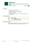
1
Artisan Technology Group is your source for quality
new and certified-used/pre-owned equipment
• FAST SHIPPING AND
DELIVERY
• TENS OF THOUSANDS OF
IN-STOCK ITEMS
• EQUIPMENT DEMOS
• HUNDREDS OF
MANUFACTURERS
SUPPORTED
• LEASING/MONTHLY
RENTALS
• ITAR CERTIFIED
SECURE ASSET SOLUTIONS
SERVICE CENTER REPAIRS
Experienced engineers and technicians on staff
at our full-service, in-house repair center
WE BUY USED EQUIPMENT
Sell your excess, underutilized, and idle used equipment
We also offer credit for buy-backs and trade-ins
www.artisantg.com/WeBuyEquipment
InstraView REMOTE INSPECTION
LOOKING FOR MORE INFORMATION?
Visit us on the web at www.artisantg.com for more
information on price quotations, drivers, technical
specifications, manuals, and documentation
SM
Remotely inspect equipment before purchasing with
our interactive website at www.instraview.com
Contact us: (888) 88-SOURCE | [email protected] | www.artisantg.com
User Guide
CC9-SAMBA • CompactPCI ® 3U Pentium ® M CPU Board
Document No. 3439 • Edition 16
2010-05
Artisan Technology Group - Quality Instrumentation ... Guaranteed | (888) 88-SOURCE | www.artisantg.com
User Guide CC9-SAMBA • CompactPCI® Pentium M CPU Board
Contents
About this Manual . . . . . . . . . . . . . . . . . . . . . . . . . . . . . . . . . . . . . . . . . . . . . . . . . . . . . . . . . . .
Edition History . . . . . . . . . . . . . . . . . . . . . . . . . . . . . . . . . . . . . . . . . . . . . . . . . . . . . . . . .
Related Documents . . . . . . . . . . . . . . . . . . . . . . . . . . . . . . . . . . . . . . . . . . . . . . . . . . . . .
Nomenclature . . . . . . . . . . . . . . . . . . . . . . . . . . . . . . . . . . . . . . . . . . . . . . . . . . . . . . . . .
Trade Marks . . . . . . . . . . . . . . . . . . . . . . . . . . . . . . . . . . . . . . . . . . . . . . . . . . . . . . . . . .
Legal Disclaimer - Liability Exclusion . . . . . . . . . . . . . . . . . . . . . . . . . . . . . . . . . . . . . . . . .
4
4
5
5
5
5
CC9-SAMBA Features . . . . . . . . . . . . . . . . . . . . . . . . . . . . . . . . . . . . . . . . . . . . . . . . . . . . . . . . . 6
Feature Summary . . . . . . . . . . . . . . . . . . . . . . . . . . . . . . . . . . . . . . . . . . . . . . . . . . . . . . 6
Short Description CC9-SAMBA . . . . . . . . . . . . . . . . . . . . . . . . . . . . . . . . . . . . . . . . . . . . . 8
Block Diagram CC9-SAMBA . . . . . . . . . . . . . . . . . . . . . . . . . . . . . . . . . . . . . . . . . . . . . . 12
Top View Component Assembly CC9-SAMBA . . . . . . . . . . . . . . . . . . . . . . . . . . . . . . . . 13
Expansion Module CCA-LAMBADA . . . . . . . . . . . . . . . . . . . . . . . . . . . . . . . . . . . . . . . . 14
Expansion Module CCB-BOSSANOVA . . . . . . . . . . . . . . . . . . . . . . . . . . . . . . . . . . . . . . . 16
Rear I/O Transition Module CCR-RIO . . . . . . . . . . . . . . . . . . . . . . . . . . . . . . . . . . . . . . . 19
Rear I/O Transition Module CCZ-RIO . . . . . . . . . . . . . . . . . . . . . . . . . . . . . . . . . . . . . . . 21
Strapping Headers . . . . . . . . . . . . . . . . . . . . . . . . . . . . . . . . . . . . . . . . . . . . . . . . . . . . . 22
Connectors & Sockets . . . . . . . . . . . . . . . . . . . . . . . . . . . . . . . . . . . . . . . . . . . . . . . . . . 22
Front Panel Elements . . . . . . . . . . . . . . . . . . . . . . . . . . . . . . . . . . . . . . . . . . . . . . . . . . . 22
Microprocessor . . . . . . . . . . . . . . . . . . . . . . . . . . . . . . . . . . . . . . . . . . . . . . . . . . . . . . . 23
Thermal Considerations . . . . . . . . . . . . . . . . . . . . . . . . . . . . . . . . . . . . . . . . . . . . . . . . . 24
Main Memory . . . . . . . . . . . . . . . . . . . . . . . . . . . . . . . . . . . . . . . . . . . . . . . . . . . . . . . . 25
LAN Subsystem . . . . . . . . . . . . . . . . . . . . . . . . . . . . . . . . . . . . . . . . . . . . . . . . . . . . . . . 26
Enhanced IDE Interface . . . . . . . . . . . . . . . . . . . . . . . . . . . . . . . . . . . . . . . . . . . . . . . . . 27
Graphics Subsystem . . . . . . . . . . . . . . . . . . . . . . . . . . . . . . . . . . . . . . . . . . . . . . . . . . . 28
Real-Time Clock . . . . . . . . . . . . . . . . . . . . . . . . . . . . . . . . . . . . . . . . . . . . . . . . . . . . . . . 29
Universal Serial Bus (USB) . . . . . . . . . . . . . . . . . . . . . . . . . . . . . . . . . . . . . . . . . . . . . . . 29
LPC Super-I/O Interface . . . . . . . . . . . . . . . . . . . . . . . . . . . . . . . . . . . . . . . . . . . . . . . . . 29
Watchdog/Reset . . . . . . . . . . . . . . . . . . . . . . . . . . . . . . . . . . . . . . . . . . . . . . . . . . . . . . 29
Firmware Hub (Flash BIOS) . . . . . . . . . . . . . . . . . . . . . . . . . . . . . . . . . . . . . . . . . . . . . . 30
PWR (Board Healthy) LED . . . . . . . . . . . . . . . . . . . . . . . . . . . . . . . . . . . . . . . . . . . . . . . . 31
IDE (Hard Disk Activity) LED . . . . . . . . . . . . . . . . . . . . . . . . . . . . . . . . . . . . . . . . . . . . . . 31
GP (General Purpose) LED . . . . . . . . . . . . . . . . . . . . . . . . . . . . . . . . . . . . . . . . . . . . . . . 31
Hot Swap Detection . . . . . . . . . . . . . . . . . . . . . . . . . . . . . . . . . . . . . . . . . . . . . . . . . . . 31
Power Supply Status (DEG#, FAL#) . . . . . . . . . . . . . . . . . . . . . . . . . . . . . . . . . . . . . . . . 32
PXI Trigger Signals . . . . . . . . . . . . . . . . . . . . . . . . . . . . . . . . . . . . . . . . . . . . . . . . . . . . . 32
Local GPIO Option . . . . . . . . . . . . . . . . . . . . . . . . . . . . . . . . . . . . . . . . . . . . . . . . . . . . . 32
Rear I/O Options . . . . . . . . . . . . . . . . . . . . . . . . . . . . . . . . . . . . . . . . . . . . . . . . . . . . . . 33
Installing and Replacing Components . . . . . . . . . . . . . . . . . . . . . . . . . . . . . . . . . . . . . . . . . . . .
Before You Begin . . . . . . . . . . . . . . . . . . . . . . . . . . . . . . . . . . . . . . . . . . . . . . . . . . . . . .
Installing the Board . . . . . . . . . . . . . . . . . . . . . . . . . . . . . . . . . . . . . . . . . . . . . . . . . . . .
Removing the Board . . . . . . . . . . . . . . . . . . . . . . . . . . . . . . . . . . . . . . . . . . . . . . . . . . .
EMC Recommendations . . . . . . . . . . . . . . . . . . . . . . . . . . . . . . . . . . . . . . . . . . . . . . . . .
Installing or Replacing the Memory Module . . . . . . . . . . . . . . . . . . . . . . . . . . . . . . . . . .
Replacement of the Battery . . . . . . . . . . . . . . . . . . . . . . . . . . . . . . . . . . . . . . . . . . . . . .
34
34
35
36
37
38
38
Technical Reference . . . . . . . . . . . . . . . . . . . . . . . . . . . . . . . . . . . . . . . . . . . . . . . . . . . . . . . . . 39
Local PCI Devices . . . . . . . . . . . . . . . . . . . . . . . . . . . . . . . . . . . . . . . . . . . . . . . . . . . . . . 39
© EKF
-2Artisan Technology Group - Quality Instrumentation ... Guaranteed | (888) 88-SOURCE | www.artisantg.com
ekf.com
User Guide CC9-SAMBA • CompactPCI® Pentium M CPU Board
Local SMB Devices . . . . . . . . . . . . . . . . . . . . . . . . . . . . . . . . . . . . . . . . . . . . . . . . . . . . .
GPIO Usage . . . . . . . . . . . . . . . . . . . . . . . . . . . . . . . . . . . . . . . . . . . . . . . . . . . . . . . . . .
GPIO Usage ICH4 . . . . . . . . . . . . . . . . . . . . . . . . . . . . . . . . . . . . . . . . . . . . . . . .
GPIO Usage FWH . . . . . . . . . . . . . . . . . . . . . . . . . . . . . . . . . . . . . . . . . . . . . . . .
GPIO Usage SIO . . . . . . . . . . . . . . . . . . . . . . . . . . . . . . . . . . . . . . . . . . . . . . . . .
GPIO Usage PCI Bridge . . . . . . . . . . . . . . . . . . . . . . . . . . . . . . . . . . . . . . . . . . . .
Configuration Jumpers . . . . . . . . . . . . . . . . . . . . . . . . . . . . . . . . . . . . . . . . . . . . . . . . .
Reset Jumper CMOS Values (JRTC) . . . . . . . . . . . . . . . . . . . . . . . . . . . . . . . . . . .
Connectors . . . . . . . . . . . . . . . . . . . . . . . . . . . . . . . . . . . . . . . . . . . . . . . . . . . . . . . . . .
Front Panel Connectors . . . . . . . . . . . . . . . . . . . . . . . . . . . . . . . . . . . . . . . . . . . .
Video Monitor Connector DVI-I . . . . . . . . . . . . . . . . . . . . . . . . . . . . . . . .
Video Monitor Connector HD-DSUB . . . . . . . . . . . . . . . . . . . . . . . . . . . . .
USB Connectors . . . . . . . . . . . . . . . . . . . . . . . . . . . . . . . . . . . . . . . . . . . .
Ethernet Connector . . . . . . . . . . . . . . . . . . . . . . . . . . . . . . . . . . . . . . . . .
Internal Connectors . . . . . . . . . . . . . . . . . . . . . . . . . . . . . . . . . . . . . . . . . . . . . .
Expansion Interface Header PEXP . . . . . . . . . . . . . . . . . . . . . . . . . . . . . . .
ATA/IDE Header PIDE . . . . . . . . . . . . . . . . . . . . . . . . . . . . . . . . . . . . . . . .
Speaker Header JSPK . . . . . . . . . . . . . . . . . . . . . . . . . . . . . . . . . . . . . . . .
PLD Programming Header ISPCON . . . . . . . . . . . . . . . . . . . . . . . . . . . . . .
Processor Debug Header PITP . . . . . . . . . . . . . . . . . . . . . . . . . . . . . . . . . .
CompactPCI J1 . . . . . . . . . . . . . . . . . . . . . . . . . . . . . . . . . . . . . . . . . . . . .
CompactPCI J2 . . . . . . . . . . . . . . . . . . . . . . . . . . . . . . . . . . . . . . . . . . . . .
Power Supply Requirements . . . . . . . . . . . . . . . . . . . . . . . . . . . . . . . . . . . . . . . . . . . . .
Literature . . . . . . . . . . . . . . . . . . . . . . . . . . . . . . . . . . . . . . . . . . . . . . . . . . . . . . . . . . .
© EKF
-3Artisan Technology Group - Quality Instrumentation ... Guaranteed | (888) 88-SOURCE | www.artisantg.com
40
40
40
41
42
42
43
43
44
44
45
46
46
47
48
48
49
50
50
51
52
53
54
54
ekf.com
User Guide CC9-SAMBA • CompactPCI® Pentium M CPU Board
About this Manual
This manual describes the technical aspects of the CC9-SAMBA, required for installation and system
integration. It is intended for the experienced user only.
Edition History
Ed.
© EKF
Contents/Changes
Author
Date
gn
2004-05-05
1
User Manual CC9-SAMBA, english, initial edition (Text # 3439, File:
cc9_uge.wpd)
2
Added images
Modified table 'Feature Summary'
Modified block diagram CC9-SAMBA
Added chapter 'Expansion Module CCB-BOSSANOVA'
Added chapter 'Rear I/O Module CCZ-RIO'
jj
14 September
2004
3
Modified table 'Feature Summary'
jj
18 October
2004
4
Modified table 'Microprocessor'
Corrected mistake in table 'Local PCI Devices'
Added values to table 'Power Supply Requirements'
jb
5 November
2004
5
Modified section 'Thermal Considerations'
Reworked Table 'Feature Summary'
Added support of Dothan755 processor
gn
2004-11-17
6
Added ICH4/GPIO19 functionality to table 'GPIO Usage ICH4'.
Added section "Reset Jumper CMOS Values (JRTC)".
gn
2005-01-25
7
Added CC9-2-SAMBA to table 'Feature Summary'
jj
7 February
2005
8
Added ICH4/GPIO32-34 functionality to table 'GPIO Usage ICH4'.
gn
2005-02-08
9
Modified operating temperature range in table 'Feature Summary'
jj
1 March 2005
10
Added MTBF in table 'Feature Summary'
Modified block Diagram (USB port number change)
jj
14 March
2005
11
Added photos CCB-BOSSANOVA
jj
25 April 2005
12
Added missing performance ratings in table 'Feature Summary'.
Added SIO/GPIO13 functionality to table 'GPIO Usage SIO'.
gn
2005-05-02
13
Added Power Supply Requirements.
gn
2005-09-13
14
Removed chapter CCF-CONCERT (mature product)
Added image CC9/CCB with front panel CF slot
Added option VLAN support with 82541PI (table 'Feature Summary')
jj
13 November
2006
15
Added information regarding Ethernet Jumbo Frame support to table
'Feature Summary'
jj
8 February
2008
16
Changed information regarding the battery
gn
2010-05-25
-4Artisan Technology Group - Quality Instrumentation ... Guaranteed | (888) 88-SOURCE | www.artisantg.com
ekf.com
User Guide CC9-SAMBA • CompactPCI® Pentium M CPU Board
Related Documents
For information about the CCA-LAMBADA refer to the CCA Technical Information Manual, available
at http://www.ekf.de/c/ccpu/cca/cca_tie.pdf.
For information about the CCB-BOSSANOVA refer to the CCB Technical Information Manual, available
at http://www.ekf.de/c/ccpu/ccb/ccb_tie.pdf.
For information regarding the CCR-RIO rear I/O transition module please read the CCR Technical
Information Manual, available at http://www.ekf.de/c/ccpu/cc9/ccr_tie.pdf.
For a description of the CC9-SAMBA BIOS see document 'PhonixBIOS User's Manual', available at
http://www.ekf.de/c/ccpu/phxbios4r6um.pdf.
For ordering information refer to document CC9-SAMBA Product Information, available at
http://www.ekf.de/c/ccpu/cc9/cc9_pie.pdf.
Nomenclature
Signal names used herein with an attached '#' designate active low lines.
Trade Marks
Some terms used herein are property of their respective owners, e.g.
Intel, Pentium, Celeron, SpeedStep: ® Intel
CompactPCI : ® PICMG
Windows 98, Windows NT, Windows 2000, Windows XP: ® Microsoft
EKF does not claim this list to be complete.
Legal Disclaimer - Liability Exclusion
This manual has been edited as carefully as possible. We apologize for any potential mistake.
Information provided herein is designated exclusively to the proficient user (system integrator,
engineer). EKF can accept no responsibility for any damage caused by the use of this manual.
© EKF
-5Artisan Technology Group - Quality Instrumentation ... Guaranteed | (888) 88-SOURCE | www.artisantg.com
ekf.com
User Guide CC9-SAMBA • CompactPCI® Pentium M CPU Board
CC9-SAMBA Features
Feature Summary
Feature Summary CC9-SAMBA
Form Factor
Single size CompactPCI style Eurocard (160x100mm2), front panel width 4HP (20.3mm)
Processor
Designed for Intel® Pentium® M Micro FC-BGA 479 processors (0.13 Banias, 0.09 Dothan),
maximum junction temperature 100°C
•
CC9-1: 600MHz ULV Celeron® M, 512KB L2 cache, 7W
•
CC9-2: 1.0GHz ULV Celeron® M (Dothan 373), 512KB L2 cache, 5W
•
CC9-3: 1.4GHz LV Pentium® M (Dothan 738), 2MB L2 cache, 10W
•
CC9-5: 1.8GHz Pentium® M (Dothan 745), 2MB L2 cache, 21W
•
CC5-6: 2.0GHz Pentium® M (Dothan 755), 2MB L2 cache, 21W
Chipset
Intel® i855 chipset consisting of:
•
82855GME Graphics/Memory Controller Hub (GMCH)
•
82801D I/O Controller Hub (ICH4)
•
82802 Compatible Firmware Hub (FWH)
Memory
200-pin SO-DIMM socket (notebook style module), PC2100/2700 DDR266/333-SDRAM, 1GB
maximum
Video I/O
Analog monitor and digital flat-panel display support by DVI-I connector (front panel), up to
2048x1536 pixel 16M colours @75Hz refresh rate (analog), up to 1600 x 1200 pixel 16M
colours @60Hz (digital), incorporates PanelLink Digital technology (Silicon Image).
•
Front panel option: D-Sub (female HD15) VGA connector available, replaces DVI-I
connector
•
Rear I/O option: Analog video across J2/P2 (CCR-RIO rear I/O transition module)
USB I/O
All ports over-current protected, data transfer rate of up to 480Mbps, conforming to USB2.0
•
USB port 1: Type A connector (front panel)
•
USB port 2: Type A connector (front panel)
•
USB ports 3/4: J2/P2 Rear I/O option (CCR-RIO rear I/O transition module)
•
USB ports 4/6: Expansion interface option (CCA-LAMBADA/CCB-BOSSANOVA
mezzanine companion board)
Ethernet I/O
•
•
•
•
Standard 10/100/1000Mbps Gigabit Ethernet controller 82541ER, accessible via RJ45
jack from the front panel or as an option across J2/P2 with attached CCR-RIO rear I/O
transition module
Jumbo Frame support up to 16KB
Option 82541PI Gigabit Ethernet controller (replaces 82541ER), Virtual LAN support,
IEEE 802.1Q VLAN tag insertion and stripping and packet filtering for up to 4096
VLAN tags
Option 10/100 Ethernet (secondary LAN port), accessible via expansion connector LCI
(LAN Connect Interface ICH4), requires 82562 PHY on expansion board (CCBBOSSANOVA)
Mezzanine I/O
•
•
•
On-board LPC/USB/AC97 Super-I/O, USB and audio expansion interface connector
Suitable CCA-LAMBADA/CCB-BOSSANOVA mezzanine companion boards available
On-board LCI (LAN Connect Interface) connector for an additional Ethernet port
(suitable mezzanine companion board CCB-BOSSANOVA)
IDE/ATA
•
Ultra ATA/100 connector (Secondary IDE), handover to CCA-LAMBADA/CCBBOSSANOVA mezzanine expansion board with optional on-board 2.5-inch hard disk
drive or external device
CompactFlash socket for a CFA ATA memory card or Microdrive® (Secondary IDE)
Option 1.8-inch on-board hard disk module (Secondary IDE), replaces CompactFlash
facility
J2/P2 Rear I/O option: Primary IDE accessible from CCR-RIO rear I/O transition module
CCR-RIO
•
•
•
© EKF
-6Artisan Technology Group - Quality Instrumentation ... Guaranteed | (888) 88-SOURCE | www.artisantg.com
ekf.com
User Guide CC9-SAMBA • CompactPCI® Pentium M CPU Board
Feature Summary CC9-SAMBA
CompactPCI
32-bit PCI bridge chip PLX PCI 6150 (HB4), 133MBps CPCI master
J2/P2 Rear I/O
•
•
•
•
•
•
•
BIOS
Phoenix BIOS
Typical Power
Requirements
Primary IDE
GB Ethernet
USB Ports 3, 5
VGA Analog Video
Keyboard, Mouse
COM1 (TTL Level)
Suitable rear I/O transition module CCR-RIO available
+3.3V +0.17V/-0.1V
Board
MaxPower
WinXP Idle
1.9A
1.9A
CC9-1-SAMBA
CC9-2-SAMBA
CC9-3-SAMBA
CC9-5-SAMBA
CC9-6-SAMBA
Thermal
Conditions
Environmental
Conditions
•
•
•
•
•
•
MTBF
90 x 103h ~ 10 years (CC9-3 @ 50°C)
Performance
Rating
Measured with
PCMark2002
under Windows
XP, 512MB
PC2700 DDR
Operating temperature: -20°C ... +70°C
Storage temperature: -20°C ... +85°C
Humidity 5% ... 95% non condensing
Altitude -300m ... +3000m
Shock 15g 0.33ms, 6g 6ms
Vibration 1g 5-2000Hz
Board
Processor
CPU/MEM Score
CC9-1-SAMBA
600MHz ULV Celeron® M (Banias)
1986/2645
CC9-2-SAMBA
1GHz ULV Celeron® M (Dothan 373)
3386/3274
CC9-3-SAMBA
1.4GHz LV Pentium® M (Dothan 738)
4745/8489
CC9-5-SAMBA
1.8GHz Pentium® M (Dothan 745)
6143/10609
CC9-6-SAMBA
2.0GHz Pentium® M (Dothan 755)
6773/11398
Subject to technical changes
© EKF
-7Artisan Technology Group - Quality Instrumentation ... Guaranteed | (888) 88-SOURCE | www.artisantg.com
ekf.com
User Guide CC9-SAMBA • CompactPCI® Pentium M CPU Board
Short Description CC9-SAMBA
Alternatively equipped with the Intel® series of
(LV) Pentium® M and ULV Celeron® M
processors and up to 1GB RAM, the CC9SAMBA is a versatile 4HP/3U (single size
Eurocard) CompactPCI® CPU board, designed
especially for systems which require low power
consumption.
Available with a variety of processors, starting
with the ULV 600MHz Celeron® M up to the
2.0GHz Pentium® M Dothan755, the CC9SAMBA covers a wide range of industrial
applications.
The DVI-I video interface allows for attachment
of both, advanced (digital) and legacy (analog)
flat panel displays and CRT monitors (D-SUB
connector optionally). The CC9-SAMBA is
provided with a Gigabit Ethernet controller. An
on-board socket accommodates either a
CompactFlash memory card or Microdrive®, or
an 1.8-inch hard disk module (option). The local
expansion interface connector may be used to
directly attach a mezzanine companion I/O
board, which can carry in addition a 2.5-inch
hard disk drive. As an option, rear I/O across the
J2/P2 connector is available.
CC9-SAMBA
© EKF
-8Artisan Technology Group - Quality Instrumentation ... Guaranteed | (888) 88-SOURCE | www.artisantg.com
ekf.com
User Guide CC9-SAMBA • CompactPCI® Pentium M CPU Board
CC9-SAMBA with CF Microdrive (or CF Flash Card)
CC9-SAMBA with 1.8-Inch HD Option
© EKF
-9Artisan Technology Group - Quality Instrumentation ... Guaranteed | (888) 88-SOURCE | www.artisantg.com
ekf.com
User Guide CC9-SAMBA • CompactPCI® Pentium M CPU Board
CompactFlash Adapter Module for CC9-SAMBA
The CC9-SAMBA comes with a CompactFlash
adapter module, which is suitable to hold a
silicon memory CF card or Microdrive hard disk.
If the CC9-SAMBA is accompanied by a
mezzanine expansion module such as the CCALAMBADA or CCB-BOSSANOVA, the position of
the CompactFlash adapter module changes to
the mezzanine card.
Optionally an on-board 1.8-inch hard disk
module is available. When ordered, it replaces
the CompactFlash adapter module (please
request for a special solution which allows to
use both the CF slot and the 1.8-inch drive
simultaneously).
1.8-Inch on-Board Hard Disk Module for CC9-SAMBA
© EKF
-10Artisan Technology Group - Quality Instrumentation ... Guaranteed | (888) 88-SOURCE | www.artisantg.com
ekf.com
User Guide CC9-SAMBA • CompactPCI® Pentium M CPU Board
CC9-SAMBA & CCR-RIO
CC9-SAMBA & CCR-RIO
© EKF
-11Artisan Technology Group - Quality Instrumentation ... Guaranteed | (888) 88-SOURCE | www.artisantg.com
ekf.com
User Guide CC9-SAMBA • CompactPCI® Pentium M CPU Board
Block Diagram CC9-SAMBA
LV Pentium® M
1.4GHz
Block Diagram
CC9-SAMBA
Pentium® M
1.8GHz
J2 VGA
VGA
D-SUB
Opt. 10/100 Ethernet
CCB-BOSSANOVA
Expansion Board
top/
bottom
512MB/1GB
PC2100/2700
Hublink
VGA
266/333MHz
DDR-SDRAM
S-IDE
LCI
GMCH
ICH4
82801
VGA
USB3
USB2.0
LPC
AC'97
PCI
SIO1
USB4/6
Opt. CCA-LAMBADA
or CCB-BOSSANOVA
Expansion Board
P-IDE
LAN
USB2.0
C10-CFA
CompactFlash
ATA
87
61
USB5
KB/MS
COM
Opt. Rear I/O
CCR-RIO
GMCH
82855
GM/E
CompactPCI
Panel DVO
Link
IDE I/F
DVI
SO-DIMM 200
PSB
400MHz
Video
GPIO
ETH
J2
Gigabit
Ethernet
PCI Bridge
USB2.0
82
541
Front Panel I/O
82
802
GB
ETH
top/
bottom
61
50
CompactPCI
FWH1
Expansion I/F
J1
Opt. CCA-LAMBADA
or CCB-BOSSANOVA
Expansion Board
© EKF
-12Artisan Technology Group - Quality Instrumentation ... Guaranteed | (888) 88-SOURCE | www.artisantg.com
ekf.com
User Guide CC9-SAMBA • CompactPCI® Pentium M CPU Board
6150
© EKF
© EKF
DDR SO-DIMM 200
VGA
DVI-I
GETH
Reset
USB
USB
541
ICH4
CC9-SAMBA
GMCH
Pentium
M
LPC/AC'97
855
Expansion Module
ATA/IDE Module
CompactFlash
PCI-Bridge
Top View Component Assembly CC9-SAMBA
-13Artisan Technology Group - Quality Instrumentation ... Guaranteed | (888) 88-SOURCE | www.artisantg.com
ekf.com
User Guide CC9-SAMBA • CompactPCI® Pentium M CPU Board
Expansion Module CCA-LAMBADA
Available as a companion board to the CC9SAMBA CPU card, the CCA-LAMBADA is
provided with common legacy I/O ports.
Interconnection between the CCA I/O module
and the CPU carrier board is achieved by the
expansion connector, which incorporates the
LPC (Low Pin Count), AC'97 (audio) and USB
interfaces.
In addition to its front panel I/O connectors, the
CCA-LAMBADA has been designed also for rear
I/O and therefore requires a non-bussed singleslot P1/P2 backplane in addition to the
CompactPCI bus. However, if front panel I/O is
solely needed, the J1/J2 connectors may be
omitted as an option.
For technical details please refer to the 'CCALAMBADA Technical Information Manual',
available at www.ekf.de/c/ccpu/cca/cca_tie.pdf.
As an option, the CCA-LAMBADA is available
with a rugged on-board 2.5-inch or 1.8-inch
hard disk drive.
The CCA-LAMBADA can be attached either left
or right (bottom or top) to the CPU board, and
is provided typically with a 4HP front panel.
CC9SAMBA
CCALAMBADA
USB
GP
C
O
M
IDE
PWR/RES
E
T
H
U
S
B
IN
A
U
D
I
O
OUT
D
V
I
K
B
/
M
S
CCA-LAMBADA
(Mounting on top of CC9)
© EKF
-14Artisan Technology Group - Quality Instrumentation ... Guaranteed | (888) 88-SOURCE | www.artisantg.com
ekf.com
User Guide CC9-SAMBA • CompactPCI® Pentium M CPU Board
CCA-LAMBADA Mounted on Bottom of CC9-SAMBA
CCA-LAMBADA Mounted on Top of CC9-SAMBA with Hard Disk Option
© EKF
-15Artisan Technology Group - Quality Instrumentation ... Guaranteed | (888) 88-SOURCE | www.artisantg.com
ekf.com
User Guide CC9-SAMBA • CompactPCI® Pentium M CPU Board
Expansion Module CCB-BOSSANOVA
The CCB-BOSSANOVA is a mezzanine
companion board to the CC9-SAMBA, very
similar to the CCA-LAMBADA.
As the CCA-LAMBADA, the CCB-BOSSANOVA is
a local expansion option, and is therefore not
essential for operation of the CC9-SAMBA.
While the audio Codec has been removed, a
secondary 10/100Mbps Ethernet port is
available.
For technical details please refer to the 'CCBBOSSANOVA Technical Information Manual',
available at www.ekf.de/c/ccpu/ccb/ccb_tie.pdf.
CC9SAMBA
CCBBOSSANOVA
CC9SAMBA
USB
USB
USB
IDE
IDE
PWR/RES
PWR/RES
E
T
H
E
T
H
E
T
H
E
T
H
P
S
2
P
S
2
D
V
I
D
V
I
C
O
M
1
© EKF
C
O
M
2
GP
GP
CCBBOSSANOVA
C
O
M
1
CCB-1-BOSSANOVA
CCB-2-BOSSANOVA
(Top Mounting on CC9)
(Top Mounting on CC9)
-16Artisan Technology Group - Quality Instrumentation ... Guaranteed | (888) 88-SOURCE | www.artisantg.com
ekf.com
User Guide CC9-SAMBA • CompactPCI® Pentium M CPU Board
CCB-2-BOSSANOVA Mounted on Top of CC9-SAMBA
CCB-2-BOSSANOVA on Top of CC9-SAMBA w/o Hard Disk
© EKF
-17Artisan Technology Group - Quality Instrumentation ... Guaranteed | (888) 88-SOURCE | www.artisantg.com
ekf.com
User Guide CC9-SAMBA • CompactPCI® Pentium M CPU Board
CC9-SAMBA / CCB-BOSSANOVA with front panel CF Card slot & on-board hard disk
© EKF
-18Artisan Technology Group - Quality Instrumentation ... Guaranteed | (888) 88-SOURCE | www.artisantg.com
ekf.com
User Guide CC9-SAMBA • CompactPCI® Pentium M CPU Board
Rear I/O Transition Module CCR-RIO
Available as a rear I/O expansion board to the
CC9-SAMBA CPU card, the CCR-RIO is provided
with several I/O port connectors, to be used
either in addition to the CC9 front panel
connectors or alternatively. Being mainly a
passive rear I/O transition module, groups of
signals from the CC9-SAMBA CPU board are
passed across the CompactPCI J2/P2 connector
to the CCR-RIO. While the IDE signals are
available locally on the CCR for internal
attachment of ATA devices, other connectors
such as USB and keyboard are mounted into
the back panel for external use.
Typically the CCR-RIO ist equipped with a 4HP
rear panel (20.3mm width). As an option, an
8HP panel is available with additional
connectors.
Utilization of the CCR-RIO transition module
adds a level of I/O functionality, which is not
available with the CC9-SAMBA CPU board
alone. Further on, swapping the CPU card is
simplified by means of rear I/O, which is
important for efficient system maintenance
(MTTR).
CCR-RIO
© EKF
-19Artisan Technology Group - Quality Instrumentation ... Guaranteed | (888) 88-SOURCE | www.artisantg.com
ekf.com
User Guide CC9-SAMBA • CompactPCI® Pentium M CPU Board
CC9-SAMBA with CF Module & CCR-RIO, Closed Front Panel for Total Rear I/O
CC9-SAMBA & Companion Board on Bottom, Closed Front Panel for Total Rear I/O
© EKF
-20Artisan Technology Group - Quality Instrumentation ... Guaranteed | (888) 88-SOURCE | www.artisantg.com
ekf.com
User Guide CC9-SAMBA • CompactPCI® Pentium M CPU Board
Rear I/O Transition Module CCZ-RIO
Available as an option to the mezzanine
modules CCA-LAMBADA and CCBBOSSANOVA, the rear I/O module CCZ-RIO
augments the number of communication ports
which are available from the systems back
panel.
For technical details please refer to the 'CCZRIO Technical Information Manual', available
at www.ekf.de/c/ccpu/ccb/ccb_tie.pdf shortly.
The CCZ-RIO may be installed in addition to the
CCR-RIO, or solely. A single slot P1/P2 rear I/O
backplane would be required.
CCZRIO
CCZRIO
V
G
A
C
O
M
E
T
H
C
O
M
D
V
I
C
O
M
E
T
H
C
O
M
U
S
B
K
B
/
M
S
M
S
© EKF
U
S
B
K
B
/
M
S
M
S
CCZ-RIO 4/8HP
CCZ-RIO 4/8HP
(VGA Video Output)
(DVI-I Video Output)
-21Artisan Technology Group - Quality Instrumentation ... Guaranteed | (888) 88-SOURCE | www.artisantg.com
ekf.com
User Guide CC9-SAMBA • CompactPCI® Pentium M CPU Board
Strapping Headers
ISPCON
PLD Programming Connector, not stuffed
JRTC
Reset Jumper CMOS Values, not stuffed
JSPK
Speaker Connector
Connectors & Sockets
J1/J2
CompactPCI Bus 32-bit, 33/66MHz, PXI, Rear I/O
PEXPT
PEXPB
Expansion Interface Connector (LPC Interface (2nd Super-I/O, 2nd
FWH), USB Interfaces, AC'97 Interface, GPIOs), available either from
top (T) or bottom (B) of the board
PIDET
PIDEB
Ultra ATA/100 Secondary IDE Port (Interface to CompactFlash ATA
Socket on C10-CFA), available either from top (T) or bottom (B) of
the board
PITP
CPU Debug Port
SODIMM1
200-pin Memory Module DDR SDRAM PC2100/2700 (DDR266/333)
Front Panel Elements
© EKF
Ethernet
(ETH)
1000Base-TX/100Base-TX/10Base-T, RJ-45 Receptacle with integrated
indicator LEDs
Graphics
(DVI)
DVI-I Integrated (digital & analog) Receptacle, suitable for DVI digital
flat panel displays and/or analog monitors
USB1/2
Universal Serial Bus 2.0 self powered root hub, type A receptacle
Reset
(PWR/RES)
Push-button Switch with integrated indicator LED (power good)
IDE
LED indicating IDE activity
GP
General Purpose LED
-22Artisan Technology Group - Quality Instrumentation ... Guaranteed | (888) 88-SOURCE | www.artisantg.com
ekf.com
User Guide CC9-SAMBA • CompactPCI® Pentium M CPU Board
Microprocessor
The CC9-SAMBA is designed for use with Pentium® M and Celeron® M processors manufactured in
0.13 (Banias) and 0.09 (Dothan) technology. These includes also the Ultra Low-Voltage (ULV)
Celeron® M and the Low-Voltage (LV) Pentium® M processors as listed below. The processors are
housed in a Micro FC-BGA package for direct soldering to the PCB, i.e. the CPU chip cannot be
removed or changed by the user.
The CC9-SAMBA supported processors are running an FSB clock of 400MHz. The internal Pentium M
processor speed is achieved by multiplying the host bus frequency by a variable value. The multiplier
is chosen by currently required performance and the actual core temperature. This technology is called
Enhanced Intel SpeedStep®.
Power is applied across the CompactPCI connectors J1 (3.3V, 5V). The processor core voltage is
generated by a switched voltage regulator, sourced from the 5V plane. The processor signals its
required core voltage by 6 dedicated pins according to Intels IMVP-IV voltage regulator specification.
0.13 Processors Supported (Banias)
Processor
Speed
min/max
[GHz]
Host Bus
[MHz]
L2 Cache
[KB]
TDP
[W]
Die Temp
[°C]
CPU ID
Stepping
sSpec
ULV Celeron M 1) 2)
0.6/0.6
400
512
7
0-100
0695h
B-1
SL7GE
LV Pentium M 2)
0.6/1.1
400
1024
12.5
0-100
0695h
B-1
SL6NC
Pentium M
0.6/1.3
400
1024
22
0-100
0695h
B-1
SL6N8
Pentium M 2)
0.6/1.6
400
1024
24.5
0-100
0695h
B-1
SL6F7
Pentium M
0.6/1.7
400
1024
24.5
0-100
0695h
B-1
SL6N9
0.09 Processors Supported (Dothan)
1)
2)
Processor
Speed
min/max
[GHz]
Host Bus
[MHz]
L2 Cache
[MB]
TDP
[W]
Die Temp
[°C]
CPU ID
Stepping
sSpec
ULV Celeron M 373 1) 2)
1.0/1.0
400
0.5
5
0-100
06D8h
C-0
SL8A4
LV Pentium M 738 2)
0.6/1.4
400
2
10
0-100
06D6h
B-1
SL7VC
Pentium M 745 2)
0.6/1.8
400
2
21
0-100
06D6h
B-1
SL7EQ
Pentium M 755
0.6/2.0
400
2
21
0-100
06D6h
B-1
SL7EL
This processor does not support SpeedStep® technology, thus it runs at a fixed core speed.
Following the Intel Embedded Roadmap, this processor is recommended for long time availability.
© EKF
-23Artisan Technology Group - Quality Instrumentation ... Guaranteed | (888) 88-SOURCE | www.artisantg.com
ekf.com
User Guide CC9-SAMBA • CompactPCI® Pentium M CPU Board
Thermal Considerations
In order to avoid malfunctioning of the CC9-SAMBA, take care of appropriate cooling of the processor
and system, e.g. by a cooling fan suitable to the maximum power consumption of the CPU chip
actually in use. Please note, that the processors temperature is steadily measured by a special
controller (MAX1617), attached to the onboard SMBus® (System Management Bus). A second sensor
internal to the MAX1617 allows for acquisition of the boards surface temperature. A suitable software
to display both, the die temperature as well as the board temperature, is MBM (Motherboard
Monitor), which can be downloaded from the web. After installation, both temperatures can be
observed permanently from the Windows taskbar.
The CC9-SAMBA is equipped with a passive heatsink. Its height takes into account the 4HP limitation
in mounting space of a CPCI board. In addition, a forced vertical airflow through the system enclosure
(e.g. bottom mount fan unit) is strongly recommended (>15m3/h or 200LFM around the CPU slot).
As an exception, the CC9-1-SAMBA (ULV Celeron M 600MHz) can be operated with natural
convection only. Be sure to thoroughly discuss your actual cooling needs with EKF. Generally, the
faster the CPU speed the higher its power consumption. For higher ambient temperatures, consider
increasing the forced airflow to 400 or 600LFM.
The tables showing the supported processors above give also the maximum power consumption (TDP
= Thermal Design Power) of a particular processor. Fortunately, the power consumption is by far
lower when executing typical Windows or Linux tasks. The heat dissipation increases when e.g.
rendering software like the Acrobat Distiller is executed.
The Pentium M processors support Intel's Enhanced SpeedStep® technology. This enables dynamic
switching between multiple core voltages and frequencies depending on core temperature and
currently required performance. The processors are able to reduce their core speed in up to 8 steps
down to 600MHz. This leads to an obvious reduction of power consumption (max. 6W @600MHz)
resulting in less heating. This mode of lowering the processor core temperature is called TM2
(TM=Thermal Monitor).
Another way to reduce power consumption is to modulate the processor clock. This mode (TM1) is
achieved by actuating the 'Stop Clock' input of the CPU. A throttling of 50% e.g. means a duty cycle
of 50% on the stop clock input. However, while saving considerable power consumption, the data
throughput of the processor is also reduced. The processor works at full speed until the core
temperature reaches a critical value. Then the processor is throttled by 50%. As soon as the high
temperature situation disappears the throttling will be disabled and the processors runs at full speed
again.
A similar feature is embedded within the Graphics and Memory Controller (GMCH) i855GME. An ondie temperature sensor is used to protect the GMCH from exceeding its maximum junction
temperature (TJ,max=110°C) by reducing the memory bandwidth.
These features are controllable by BIOS menu entries. By default the BIOS of the CC9-SAMBA enables
mode TM2 which is the most efficient. The following diagram shows exemplary on a CC9-SAMBA
with 1.4GHz Dothan® processor the differences between the thermal modes when the board is
applied to high ambient temperatures. The performance (processor and memory scores) was
measured with the benchmark 'PCMark2002' on a Windows 2000/SP4 platform (device under test was
a CC9-3R-SAMBA with 512MB PC2700 DDR SDRAM, airflow approx. 500LFM).
© EKF
-24Artisan Technology Group - Quality Instrumentation ... Guaranteed | (888) 88-SOURCE | www.artisantg.com
ekf.com
User Guide CC9-SAMBA • CompactPCI® Pentium M CPU Board
Main Memory
The CC9-SAMBA is equipped with a socket for installing a single 200-pin SO-DIMM module (module
height = 1.25 inch). Supported are unbuffered SODIMMs without ECC, according the PC1600,
PC2100 or PC2700 specification. Minimum memory size is 128MB; maximum memory size is
1024MB. Due to the video requirements of the i855GME chipset, a minimum of 256MB of memory
is recommended for the operating systems Windows NT 4.0, Windows 2000 or Windows XP (some
of the system memory is dedicated to the graphics controller). The contents of the SPD EEPROM on
the SO-DIMM is used by the BIOS at POST (Power-on Self Test) to program the memory controller
within the chipset.
© EKF
-25Artisan Technology Group - Quality Instrumentation ... Guaranteed | (888) 88-SOURCE | www.artisantg.com
ekf.com
User Guide CC9-SAMBA • CompactPCI® Pentium M CPU Board
LAN Subsystem
The CC9-SAMBA is equipped with an 82541ER Gigabit Ethernet controller. The Intel 82541ER Gigabit
Ethernet PCI LAN subsystem provides also legacy 10Base-T and 100Base-TX connectivity. Features
include:
C
C
C
C
PCI bus mastering 32-bit, 33MHz
1000Base-Tx (Gigabit Ethernet), 100Base-TX (Fast Ethernet, half- or full-duplex) and 10Base-T
(Classic Ethernet) capability using a single RJ-45 connector
IEEE 802.3 Auto-Negotiation for the fastest available connection
Jumperless configuration (complete software-configurable)
Available as an option, the CC9-SAMBA can be equipped with the 82541PI Gigabit Ethernet controller,
which replaces the 82541ER. The 82541PI silicon supports in addition Virtual LANs by IEEE 802.1Q VLAN tag insertion
and stripping and packet filtering for up to 4096 VLAN tags.
Two bicoloured display LEDs integrated into the RJ-45 connector signal the LAN link, the LAN
connection speed and activity status.
The NIC (Networking Interface Controller) resides on the local PCI bus. Its MAC address (unique
hardware number) is stored in an EEPROM. The Intel Ethernet software and drivers for the 82541ER
is available from Intel's World Wide Web site for download.
Please note that a secondary 10/100Mbps Ethernet port is available across the LCI (LAN connect
interface) expansion connector. A suitable mezzanine card with the 82562 LCI PHY is the CCBBOSSANOVA.
© EKF
-26Artisan Technology Group - Quality Instrumentation ... Guaranteed | (888) 88-SOURCE | www.artisantg.com
ekf.com
User Guide CC9-SAMBA • CompactPCI® Pentium M CPU Board
Enhanced IDE Interface
The EIDE interface handles the exchange of information between the processor and peripheral devices
like hard disks, ATA CompactFlash cards and CD-ROM drives. The interface supports:
C
C
C
Up to four ATA devices (including one CompactFlash slot)
PIO Mode 3/4, Ultra ATA/33, Ultra ATA/66, Ultra ATA/100
Support for LS-120 drives
The primary IDE interface is routed to the CompactPCI J2 connector. The rear I/O adapter CCR-RIO
allows the connection of a master and a slave IDE device via a standard 40-pin flat ribbon cable (use
special 80-pin cabling assembly for Ultra ATA/66 or /100 operation).
The presence of an 80-pin cable at the primary IDE interface could be checked out by reading the
state of the GPI8 of the I/O Controller Hub (ICH4). A logical 1 signals a 40-pin, a logical 0 a 80-pin
cable. See the ATA/ATAPI-6 specification (section 6.7 “Host determination of cable type by detecting
CBLID-“) for details.
The secondary IDE interface is routed to the on-board connectors PIDET and PIDEB (T:top side,
B:bottom side of the board). PIDE is used to interface to the CompactFlash Card adapter C10-CFA or
to the expansion board CCA-LAMBADA. Use the C10-CFA adapter to attach a CompactFlash ATA style
silicon disk, whenever a hard disk is not suitable for your system, or as an additional mass storage
device. The CCA-LAMBADA expansion board is capable to carry an on-board 1.8" or 2.5" hard disk
drive. When using the 1.8" option the concurrent operation of a CompactFlash device is possible.
A display LED, situated in the front panel near the reset push-button, signals disk activity status of the
primary and also the secondary IDE devices.
The IDE controller is integrated into the ICH4. Ultra ATA IDE drivers can be downloaded from the Intel
website.
© EKF
-27Artisan Technology Group - Quality Instrumentation ... Guaranteed | (888) 88-SOURCE | www.artisantg.com
ekf.com
User Guide CC9-SAMBA • CompactPCI® Pentium M CPU Board
Graphics Subsystem
The graphics subsystem is part of the Intel i855GME Graphics/Memory Controller Hub (GMCH). The
CC9-SAMBA is provided with the DVI-I graphics connector. This is both a digital and analog interface.
Recent digital input flat-panel displays are widely available with this connector style. For classic
monitors, adapters or adapter cables can be used for converting from DVI-I to the 15-pin HD D-SUB
connector.
A special display transmitter chip is used for serializing/deserializing the differential DVI signals. The SiI
164 (Silicon Image) transmitter uses PanelLink® Digital technology to support displays ranging from
VGA to UXGA resolutions (25 - 165Mpps) in a single link interface.
The GMCH supports several video resolutions and refresh rates. A partial list is contained in the table
below. Please note, that flat-panel displays should be operated with their maximum resolution at
60Hz refresh rate.
Partial List of i855GME GMCH Video Modes (analog / digital)
1)
Resolution
60Hz
70Hz
72Hz
75Hz
85Hz
640x480
T/T
T/T
T/T
T/T
T/T
800x600
T/T
T/T
T/T
T/T
T/T
1024x768
T / T1)
T/T
T/T
T/T
T/T
1280x1024
T / T1)
T/T
T/T
T/T
T/T
1600x1200
T / T1)
T/-
T/-
T/-
T/-
2048x1536
T/-
T/-
T/-
T/-
-/-
This video mode is suitable for popular flat-panel displays.
As an option, the CC9-SAMBA can be equipped with an ordinary HD D-Sub 15-lead connector (VGA
style). This connector is suitable for analog signals only, so the PanelLink transmitter is not stuffed
with this option. Nevertheless also flat-panel displays can be attached to the D-Sub connector with
only minor impact on the image quality.
Independent from the video connector actually in use, DVI or VGA, the VESA DDC 2B standard is
supported. This is a two-wire serial bus (clock, data), which is controlled by the GMCH and allows to
read out important parameters, e.g. the maximum allowable resolution, from the attached monitor.
In addition, DDC Power (+5V) is delivered to either connector. A resettable fuse is stuffed to protect
the board from an external short-circuit condition (0.75A).
Graphics drivers for the i855GME can be downloaded from the Intel website.
Real-Time Clock
The CC9-SAMBA has a time-of-day clock and 100-year calendar, integrated into the ICH4. A battery
on the board keeps the clock current when the computer is turned off. The CC9 uses a VanadiumPentoxide-Lithium rechargeable battery, giving an autonomy of more than 80 days when fully loaded
after 24 hours. The cell is free of memory effects and withstands deep discharging.
© EKF
-28Artisan Technology Group - Quality Instrumentation ... Guaranteed | (888) 88-SOURCE | www.artisantg.com
ekf.com
User Guide CC9-SAMBA • CompactPCI® Pentium M CPU Board
Universal Serial Bus (USB)
The CC9-SAMBA is provided with six USB ports, all of them are USB 2.0 capable. Two USB interfaces
are routed to front panel connectors, two ports are feed to the expansion board interface connectors
PEXP, and two further ports are optionally available for rear I/O across the J2/P2 CompactPCI
connector.
The front panel USB connectors can source up to 0.5A/5V each, over-current protected by two
electronic switches. Protection for the USB ports on the expansion interface and on the rear I/O
connector is located on the CCA-LAMBADA and the CCR-RIO respective. The USB controllers are
integrated into the ICH4.
LPC Super-I/O Interface
In a modern system, legacy ports as PS/2 keyboard/mouse, COM1/2 and LPT have been replaced by
USB and Ethernet connectivity. The 1.4MB floppy disk drive has been swapped against LS-120 or CDRW drives, attached to the IDE connector, or USB memory sticks. Hence, the CC9-SAMBA is virtually
provided with all necessary I/O ports. However, for compatibility purposes the CC9 is additionally
equipped with a simple Super-I/O chip, for optional rear I/O of PS/2 keyboard/mouse and COM1 (TTL
level only) across the J2/P2 CPCI connector. The Super-I/O controller resides on the local LPC bus (LPC
= Low Pin Count interface standard), which is a serialized ISA bus replacement.
As an alternative, EKF offers the CCA-LAMBADA, an expansion module to the CC9-SAMBA, featuring
all classic Super-I/O functionality. The CCA-LAMBADA is a 3U Eurocard with a 4HP (single) width front
panel. Access to the connectors PS/2 (mouse, keyboard), COM, USB and audio in/out is given directly
from the front panel. The CCA-LAMBADA connects to the CC9-SAMBA across the connector PEXPT or
PEXPB. The CCA-LAMBADA can be attached either to the top or to the bottom of the CC9-SAMBA.
Watchdog/Reset
The CC9-SAMBA is provided with two MAX6705 supervisor circuits, which monitor the supply
voltages 2.5V, 3.3V and 5V, and generate a power-on reset signal. The manual push-button reset is
also passed through the MAX6705s for appropriate pulse conditioning.
The reset manual push-button is situated at the front panel. The button is indent mounted behind the
front and requires a tool, e.g. pen to be pressed, preventing from being inadvertently activated. The
push button reset signal is routed across a PLD (programmable logic device) and could be passivated
on customers request.
The healthy state of the CC9-SAMBA is signalled by the LED PWR integrated into the reset pushbutton. As soon as this LED begins to shine all power voltages are well and the reset signal has been
deasserted.
Another feature is the watchdog function, which can be programmed by software. The behaviour of
the MAX6705 watchdog is partially defined by the PLD, which controls whether the watchdog is
activated. The related software (e.g. BIOS, application program) must trigger the watchdog by
toggling the GPO21 signal of the ICH4.
© EKF
-29Artisan Technology Group - Quality Instrumentation ... Guaranteed | (888) 88-SOURCE | www.artisantg.com
ekf.com
User Guide CC9-SAMBA • CompactPCI® Pentium M CPU Board
The watchdog is in a passive state after a system reset. There is no need to trigger it at boot time.
Once the GPO21 of the ICH4 has sent a pulse, the watchdog is activated. If the duration between two
trigger pulses exceeds a period of 1000ms, the watchdog times out and a system reset will be
generated. The watchdog remains in the active state until the next system reset. There is no way to
disable it once it was started.
Firmware Hub (Flash BIOS)
The BIOS is stored in an 82802 8Mbit Firmware Hub (there are second sources in use with deviant
part numbers). The firmware hub contains a nonvolatile memory core based on flash technology,
allowing the BIOS to be upgraded.
The FWH can be reprogrammed (if suitable) by a DOS based tool. This program and the latest CC9SAMBA BIOS are available from the EKF website. Read carefully the enclosed instructions. If the
programming procedure fails e.g. caused by a power interruption, the CC9-SAMBA may no more be
operable. In this case you would have to send in the board, because the BIOS is directly soldered to
the PCB and cannot be changed by the user.
© EKF
-30Artisan Technology Group - Quality Instrumentation ... Guaranteed | (888) 88-SOURCE | www.artisantg.com
ekf.com
User Guide CC9-SAMBA • CompactPCI® Pentium M CPU Board
PWR (Board Healthy) LED
The CC9-SAMBA offers a software programmable LED located in the reset push-button. After system
reset, this LED defaults to signal the board healthy. By the first setting of the GPO20 of the ICH4 this
LED changes its function and is then controlled only by the level of the GPO20 pin. Setting this pin to
1 will switch on the LED. The PWR LED remains in the programmable state until the next system reset.
IDE (Hard Disk Activity) LED
The CC9-SAMBA offers a LED, marked as IDE (placed near the reset push-button). This LED signals
activity on any of the IDE ports.
GP (General Purpose) LED
A second, programmable LED can be also observed from the front panel. The status of the GP LED is
controlled by the GPO18 output of the ICH4. Setting this pin to 1 will switch on the LED. As of
current, the GP LED is not dedicated to any particular hardware or firmware function (this may change
in the future).
Hot Swap Detection
The CompactPCI specification added the signal ENUM# to the PCI bus to allow the system hot
swapping. This signal is routed to the GPI0 of the ICH4 on the CC9-SAMBA. A System Management
Interrupt (SMI) can be requested if ENUM# changes by insertion or removal of a board.
Note that the CC9-SAMBA itself is not a hot swap device, because it makes no sense to remove the
system controller from a CompactPCI system. However, it is capable to recognize the hot swap of
peripheral boards and to start software that is doing any necessary system reconfiguration.
© EKF
-31Artisan Technology Group - Quality Instrumentation ... Guaranteed | (888) 88-SOURCE | www.artisantg.com
ekf.com
User Guide CC9-SAMBA • CompactPCI® Pentium M CPU Board
Power Supply Status (DEG#, FAL#)
Power supply failures may be detected before the system crashes down by monitoring the signals
DEG# or FAL#. These active low lines are additions of the CompactPCI specification and may be
driven by the power supply. DEG# signals the degrading of the supply voltages, FAL# there possible
failure. On the CC9-SAMBA FAL# is routed to the GPI6 and DEG# to the GPI7 of the ICH4.
PXI Trigger Signals
As an option, the CC9-SAMBA supports four of the eight trigger signals of the PXI standard, as
defined by National Instruments. The trigger signals are provided by the local SIO (Super-I/O) chip
IT8761E. GPIO20/21 are routed to TRIG0/1, and GPIO26/27 are used to control TRIG6/7. These signals
can also be used as GPIO lines in a non-PXI environment.
Local GPIO Option
In addition to the GPIO / PXI-Trigger lines optionally available on J2, the expansion connector PEXP
provides another two GPIO lines available for user specific application. The 5V TTL signals
sio_gpio16/17 are controlled by the on-board SIO IT8761E, with an internal 50kΩ PU resistor and
capable of sinking 24mA each.
© EKF
-32Artisan Technology Group - Quality Instrumentation ... Guaranteed | (888) 88-SOURCE | www.artisantg.com
ekf.com
User Guide CC9-SAMBA • CompactPCI® Pentium M CPU Board
Rear I/O Options
Optionally, the CC9-SAMBA can be used for rear I/O with respect to the following functions:
•
•
•
•
•
•
Analog Graphics
Gigabit Ethernet
Primary IDE
2 USB Ports
Keyboard, Mouse
COM1 (TTL Level)
The analog graphics and the gigabit ethernet signals are routed to multiplexers on the CC9-SAMBA.
These switches, controlled by BIOS, select either the front panel or the rear I/O connection. Keyboard
and mouse as well as the serial interface require the on-board SIO to be stuffed. The COM1 port does
not include the physical transceiver (TTL level only). This transceiver is located on the rear I/O module
CCR-RIO instead. Each of the above functions can be activated individually (by appropriate
stuffing/removing of resistor networks).
The CC9 CPU card by default is suitable for a 64-bit CompactPCI backplane. However, the J2/P2 pin
assignments of a 64-bit CPCI backplane differ substantially from a CompactPCI rear I/O backplane.
Hence usage of the rear I/O features is available only as stuffing options on the CC9 CPU board, which
have to be ordered explicitly.
The system in use must be equipped with a P2 CompactPCI rear I/O backplane. If the system is
provided with a P2 CompactPCI 64-bit backplane instead, several of the CC9 rear I/O signals will
collide with the 64-bit address/data lines on the backplane, with unpredictable results regarding the
rear I/O signal integrity.
© EKF
-33Artisan Technology Group - Quality Instrumentation ... Guaranteed | (888) 88-SOURCE | www.artisantg.com
ekf.com
User Guide CC9-SAMBA • CompactPCI® Pentium M CPU Board
Installing and Replacing Components
Before You Begin
Warnings
The procedures in this chapter assume familiarity with the general terminology associated with
industrial electronics and with safety practices and regulatory compliance required for using and
modifying electronic equipment. Disconnect
the system from its power source and from
any telecommunication links, networks or
modems before performing any of the
procedures described in this chapter. Failure
to disconnect power, or telecommunication
links before you open the system or perform
any procedures can result in personal injury
or equipment damage. Some parts of the
system can continue to operate even though
the power switch is in its off state.
Caution
Electrostatic discharge (ESD) can damage components. Perform the procedures described in this
chapter only at an ESD workstation. If such a
station is not available, you can provide
some ESD protection by wearing an
antistatic wrist strap and attaching it to a
metal part of the system chassis or board
front panel. Store the board only in its
original ESD protected packaging. Retain the
original packaging (antistatic bag and
antistatic box) in case of returning the board to EKF for rapair.
© EKF
-34Artisan Technology Group - Quality Instrumentation ... Guaranteed | (888) 88-SOURCE | www.artisantg.com
ekf.com
User Guide CC9-SAMBA • CompactPCI® Pentium M CPU Board
Installing the Board
Warning
This procedure should be done only by qualified technical personnel. Disconnect the system from its
power source before doing the procedures described here. Failure to disconnect power, or
telecommunication links before you open the system or perform any procedures can result in personal
injury or equipment damage.
Typically you will perform the following steps:
C
Switch off the system, remove the AC power cord
C
Attach your antistatic wrist strap to a metallic part of the system
C
Remove the board packaging, be sure to touch the board only at the front panel
C
Identify the related CompactPCI slot (peripheral slot for I/O boards, system slot for CPU boards,
with the system slot typically most right or most left to the backplane)
C
Insert card carefully (be sure not to damage components mounted on the bottom side of the
board by scratching neighboured front panels)
C
A card with onboard connectors requires attachment of associated cabling now
C
Lock the ejector lever, fix screws at the front panel (top/bottom)
C
Retain original packaging in case of return
© EKF
-35Artisan Technology Group - Quality Instrumentation ... Guaranteed | (888) 88-SOURCE | www.artisantg.com
ekf.com
User Guide CC9-SAMBA • CompactPCI® Pentium M CPU Board
Removing the Board
Warning
This procedure should be done only by qualified technical personnel. Disconnect the system from its
power source before doing the procedures described here. Failure to disconnect power, or
telecommunication links before you open the system or perform any procedures can result in personal
injury or equipment damage.
Typically you will perform the following steps:
C
Switch off the system, remove the AC power cord
C
Attach your antistatic wrist strap to a metallic part of the system
C
Identify the board, be sure to touch the board only at the front panel
C
unfasten both front panel screws (top/bottom), unlock the ejector lever
C
Remove any onboard cabling assembly
C
Activate the ejector lever
C
Remove the card carefully (be sure not to damage components mounted on the bottom side
of the board by scratching neighboured front panels)
C
Store board in the original packaging, do not touch any components, hold the board at the
front panel only
Warning
Do not expose the card to fire. Battery cells and other components could explode
and cause personal injury.
© EKF
-36Artisan Technology Group - Quality Instrumentation ... Guaranteed | (888) 88-SOURCE | www.artisantg.com
ekf.com
User Guide CC9-SAMBA • CompactPCI® Pentium M CPU Board
EMC Recommendations
In order to comply with the CE regulations for EMC, it is mandatory to observe the following rules:
C
The chassis or rack including other boards in use must comply entirely with CE
C
Close all board slots not in use with a blind front panel
C
Front panels must be fastened by built-in screws
C
Cover any unused front panel mounted connector with a shielding cap
C
External communications cable assemblies must be shielded (shield connected only at one end
of the cable)
C
Use ferrite beads for cabling wherever appropriate
C
Some connectors may require additional isolating parts
Reccomended Accessories
© EKF
Blind CPCI Front
Panels
EKF Elektronik
Widths currently available
(1HP=5.08mm):
with handle 4HP/8HP
without handle
2HP/4HP/8HP/10HP/12HP
Ferrit Bead Filters
ARP Datacom,
63115 Dietzenbach
Ordering No.
102 820 (cable diameter 6.5mm)
102 821 (cable diameter 10.0mm)
102 822 (cable diameter 13.0mm)
Metal Shielding
Caps
Conec-Polytronic,
59557 Lippstadt
Ordering No.
CDFA 09 165 X 13129 X (DB9)
CDSFA 15 165 X 12979 X (DB15)
CDSFA 25 165 X 12989 X (DB25)
-37Artisan Technology Group - Quality Instrumentation ... Guaranteed | (888) 88-SOURCE | www.artisantg.com
ekf.com
User Guide CC9-SAMBA • CompactPCI® Pentium M CPU Board
Installing or Replacing the Memory Module
Note: If you decide to replace the memory, observe the precautions in 'Before You Begin'
By default, the CC9-SAMBA comes fully equipped and tested with a DDR SD-RAM memory module.
So normally there should be no need to install a memory module.
The CC9-SAMBA requires a PC1600/2100/2700 (200/266/333MHz) DDR SDRAM SO-DIMM module.
It is highly recommended that Serial Presence Detect (SPD) SO-DIMMs be used, since this allows the
chipset to accurately configure the memory settings for optimum performance. If non-SPD memory
is installed, the BIOS will attempt to correctly configure the memory settings, but performance and
reliability may be impacted.
A replacement memory module must match the 200-pin SO-DIMM form factor (known from
Notebook PCs), 2.5V, 200/266/333MHz, unbuffered, non-ECC style. Suitable modules are available up
to 1GB. The i855GME supports modules of up to a maximum of 13 address lines (A0...A12). Memory
modules organized by more than13 address lines are not suitable.
Replacement of the Battery
When your system is turned off, a battery maintains the voltage to run the time-of-day clock and to
keep the values in the CMOS RAM. The rechargeable battery is soldered to the CC9-SAMBA. For
replacement, the old battery must be desoldered, and the new one soldered. We suggest that you
send back the board to EKF for battery replacement.
Warning
Danger of explosion if the battery is incorrectly replaced. Replace only with the same or
equivalent type. Do not expose a battery to fire.
© EKF
-38Artisan Technology Group - Quality Instrumentation ... Guaranteed | (888) 88-SOURCE | www.artisantg.com
ekf.com
User Guide CC9-SAMBA • CompactPCI® Pentium M CPU Board
Technical Reference
Local PCI Devices
The following table shows the on-board PCI devices and their location within the PCI configuration
space. These devices consist of the Ethernet controller, the PCI-To-PCI Bridge and several devices
within the i855GME chip set.
1)
Bus
Number
Device
Number
Function
Number
Vendor ID
Device ID
Description
0
0
0
0x8086
0x3580
Host Bridge
0
0
1
0x8086
0x3584
Main Memory Controller
0
0
3
0x8086
0x3585
GMCH Config. Registers
0
2
0
0x8086
0x3582
Integrated Graphics Device
0
29
0
0x8086
0x24C2
USB UHCI Controller #1
0
29
1
0x8086
0x24C4
USB UHCI Controller #2
0
29
2
0x8086
0x24C7
USB UHCI Controller #3
0
29
7
0x8086
0x24CD
USB 2.0 EHCI Controller
0
30
0
0x8086
0x244E
Hub Interface Bridge
0
31
0
0x8086
0x24C0
LPC Bridge
0
31
1
0x8086
0x24CB
IDE Controller
0
31
3
0x8086
0x24C3
SMB Controller
0
31
5
0x8086
0x24C5
AC'97 Audio Controller
0
31
6
0x8086
0x24C6
AC'97 Modem Controller
2 1)
1
0
0x8086
0x1078
Ethernet Controller
2 1)
4
0
0x3388
0x0022
PCI-To-PCI Bridge (CPCI)
This bus number can vary depending on the PCI enumeration schema implemented in BIOS.
© EKF
-39Artisan Technology Group - Quality Instrumentation ... Guaranteed | (888) 88-SOURCE | www.artisantg.com
ekf.com
User Guide CC9-SAMBA • CompactPCI® Pentium M CPU Board
Local SMB Devices
The CC9-SAMBA contains a few devices that are reachable via the System Management Bus (SMB).
These are the clock generation chip, the SPD EEPROM on the SO-DIMM memory module and a CPU
temperature controlling device in particular. Other devices could be connected to the SMB via the
CompactPCI signals IPMB SCL (J1 B17) and IPMB SDA (J1 C17).
Address
Description
0x30
CPU Temperature Sensor MAX 1617
0xA0
SPD of SO-DIMM
0xD2
Main Clock Generation (CK-408)
GPIO Usage
GPIO Usage ICH4
CC9-SAMBA GPIO Usage ICH4
Function
GPIO
Type
Tol.
Origin/Destination
CPCI_ENUM#
GPI 0
I
5V
CPCI Hot Swap Mgmt.
CPCI_INTP
GPI 1
I
5V
CPCI INTP Line
PCI_IRQE#
GPI 2
I
5V
CPCI INTP Line
PCI_IRQF#
GPI 3
I
5V
CPCI INTC#
PCI_IRQG#
GPI 4
I
5V
CPCI INTD#
PCI_IRQH#
GPI 5
I
5V
ICH4 USB 2.0 Controller
CPCI_FAL#
GPI 6
I
5V
CPCI Power Mgmt.
CPCI_DEG#
GPI 7
I
5V
CPCI Power Mgmt.
IDEP_CBLID#
GPI 8
I
3.3V
IDE Primary Cable ID Line
-
INTRUDER#
I
3.3V
-
IDES_CBLID#
GPI 11
I
3.3V
IDE Secondary Cable ID Line
EXP_PME#
GPI 12
I
3.3V
Expansion Interface PME# Line
EXP_SMI#
GPI 13
I
3.3V
Expansion Interface SMI# Line
-
GPO 16
O
3.3V
-
-
GPO 17
O
3.3V
-
ICH_GPO18
GPO 18
O
3.3V
PLD (GP LED Control)
RTCRST# 1)
GPO 19
O
3.3V
ICH4 (RTCRST# Input)
ICH_GPO20
GPO 20
O
3.3V
PLD (PWR LED Control)
© EKF
-40Artisan Technology Group - Quality Instrumentation ... Guaranteed | (888) 88-SOURCE | www.artisantg.com
ekf.com
User Guide CC9-SAMBA • CompactPCI® Pentium M CPU Board
CC9-SAMBA GPIO Usage ICH4
Function
GPIO
Type
Tol.
Origin/Destination
WDOG_TRG#
GPO 21
O
3.3V
PLD (HW Watchdog Trigger)
-
GPO 22
OD
3.3V
-
-
GPO 23
O
3.3V
-
SMB_CPCI_EN
GPIO 24
I/O
3.3V
Connect CPCI IPMB to local SMBus
LOW: IPMB disconnected from SMBus
HIGH: IPMB connected to SMBus
-
GPIO 25
I/O
3.3V
-
VGA_SWITCH
GPIO 27
I/O
3.3V
VGA Switching Line:
LOW: VGA via Rear I/O
HIGH: VGA via Front I/O
ETH_SWITCH
GPIO 28
I/O
3.3V
Ethernet Switching Line:
LOW: Ethernet via Rear I/O
HIGH: Ethernet via Front I/O
GPIO 32-34
I
3.3V
Board Configuration Jumpers
I/O
3.3V
-
BOARD_CFG
1)
1)
GPIO 35-43
Feature available as of revision 2.
GPIO Usage FWH
CC9-SAMBA GPIO Usage FWH
Function
GPIO
Type
Tol.
Origin/Destination
FWH_ID
GPI 0
I
3.3V
FWH Identity: Hardwired to LOW
(indicates FWH #1)
-
GPI 1
I
3.3V
-
WDOGRST
GPI 2
I
3.3V
PLD (Last HW Reset caused by
watchdog)
MSB PCB REV
GPI 3
I
3.3V
LSB PCB REV
GPI 4
I
3.3V
© EKF
GPI 3 GPI 4 Rev.
0
0
0
0
1
1
1
0
2
1
1
3+
-41Artisan Technology Group - Quality Instrumentation ... Guaranteed | (888) 88-SOURCE | www.artisantg.com
ekf.com
User Guide CC9-SAMBA • CompactPCI® Pentium M CPU Board
GPIO Usage SIO
CC9-SAMBA GPIO Usage SIO
1)
Function
GPIO
Type
Tol.
Origin/Destination
CPCI_64EN# 1)
GPIO 13
I
5V int. PU
CompactPCI 64EN# J2/P2
-
GPIO 14/15
I/O
5V int. PU 8mA
-
SIO_GPIO16
GPIO 16
I/O
5V int. PU 24mA
Expansion Interface GPIO
SIO_GPIO17
GPIO 17
I/O
5V int. PU 24mA
Expansion Interface GPIO
PXI_TRIG0
GPIO 20
I/O
5V int. PU 8mA
PXI Trigger 0 J2/P2
PXI_TRIG1
GPIO 21
I/O
5V int. PU 8mA
PXI Trigger 1 J2/P2
-
GPIO 22-25
I/O
5V int. PU 24mA
-
PXI_TRIG6
GPIO 26
I/O
5V int. PU 24mA
PXI Trigger 6 J2/P2
I/O
5V int. PU 24mA
PXI Trigger 7 J2/P2
PXI_TRIG7
GPIO 27
Feature available as of revision 3.
GPIO Usage PCI Bridge
CC9-SAMBA GPIO Usage PCI-PCI Brigde
Function
GPIO
Type
Tol.
Origin/Destination
-
GPIO 0
I/O
3.3V
-
-
GPIO 1
I/O
3.3V
-
EN_INTS_SI
GPIO 2
I/O
3.3V
Connect CPCI INTS Line to local SERIRQ
LOW: INTS disconnected from SERIRQ
HIGH: INTS connected to SERIRQ
CPCI_SYSEN#
GPIO 3
I/O
3.3V
CPCI SYSEN# Line
© EKF
-42Artisan Technology Group - Quality Instrumentation ... Guaranteed | (888) 88-SOURCE | www.artisantg.com
ekf.com
User Guide CC9-SAMBA • CompactPCI® Pentium M CPU Board
Configuration Jumpers
Reset Jumper CMOS Values (JRTC)
The jumper JRTC is used to bring the contents of the battery backed CMOS RAM to a default state.
The BIOS uses the CMOS to store configuration values, e.g. the actual boot devices.
To reset the CMOS RAM the board must be removed from the system rack. Short-circuit the pins of
JRTC for about 1 sec. After that reinstall the board to the system and switch on the power. It is
important to accomplish the CMOS reset while the board has no power.
JRTC
Function
Jumper OFF 1)
No CMOS reset performed
Jumper ON
CMOS reset performed
Note:
1)
This setting is the factory default.
© EKF
-43Artisan Technology Group - Quality Instrumentation ... Guaranteed | (888) 88-SOURCE | www.artisantg.com
ekf.com
User Guide CC9-SAMBA • CompactPCI® Pentium M CPU Board
Connectors
Caution
Some of the internal connectors provide operating voltage (3.3V and 5V) to devices inside the system
chassis, such as internal peripherals. Not all of these connectors are overcurrent protected. Do not use
these internal connectors for powering devices external to the computer chassis. A fault in the load
presented by the external devices could cause damage to the board, the interconnecting cable and
the external devices themselves.
Front Panel Connectors
CC9SAMBA
CC9SAMBA
USB
USB
GP
GP
IDE
PWR/RES
E
T
H
D
V
I
Draft - do not scale © EKF
IDE
PWR/RES
E
T
H
V
G
A
CC9-SAMBA Front Panel Elements
© EKF
-44Artisan Technology Group - Quality Instrumentation ... Guaranteed | (888) 88-SOURCE | www.artisantg.com
ekf.com
User Guide CC9-SAMBA • CompactPCI® Pentium M CPU Board
Video Monitor Connector DVI-I
DVI-I
17
1
9
24
16
8
c3
c1
c4
c2
c6
1)
17
TX0-
9
TX1-
1
TX2-
18
TX0+
10
TX1+
2
TX2+
19
GND
11
GND
3
GND
20
12
4
21
13
5
22
GND
14
DDC_POW 1)
6
DDC_SCL
23
TXC+
15
GND
7
DDC_SDA
24
TXC-
16
DVI_HP
8
VSYNC
c5
c3
BLUE
c1
RED
c6
GND
c5
GND
c4
HSYNC
c2
GREEN
+5V protected by a PolySwitch Fuse 0.75A
For attachment of an ordinary analog RGB monitor to the DVI receptacle, there are both adapters and
also adapter cables available from DVI-I to the HD-SUB15 connector. Attachment of digital monitors
(flat panel displays) should be done by means of a DVI to DVI cable (single link style cable is sufficient).
© EKF
-45Artisan Technology Group - Quality Instrumentation ... Guaranteed | (888) 88-SOURCE | www.artisantg.com
ekf.com
User Guide CC9-SAMBA • CompactPCI® Pentium M CPU Board
Video Monitor Connector HD-DSUB
As an option, the CC9-SAMBA can be equipped with a legacy VGA connector (High-Density D-Sub 15position female connector). The VGA connector replaces the DVI receptacle, and the digital video
interface therefore is not available with this option.
VGA1 (Option)
10
5
15
11
1
6
1)
+5V protoected by a PolySwitch Fuse 0.75A
1
RED
2
GREEN
3
BLUE
4
NC
5
GND
6
GND
7
GND
8
GND
9
DDC_POW 1)
10
GND
11
NC
12
DDC_SDA
13
HSYNC
14
VSYNC
15
DDC_SCL
USB Connectors
USB Ports 1/2
1
1)
© EKF
4
+5V protected by an Electronic Fuse 0.5A
1
POW 1)
2
USB DATA NEG
3
USB DATA POS
4
GND
-46Artisan Technology Group - Quality Instrumentation ... Guaranteed | (888) 88-SOURCE | www.artisantg.com
ekf.com
User Guide CC9-SAMBA • CompactPCI® Pentium M CPU Board
Ethernet Connector
ETH (RJ45)
8
1
1
MDX0+
2
MDX0-
3
MDX1+
4
MDX2+
5
MDX2-
6
MDX1-
7
MDX3+
8
MDX3-
The upper green/yellow dual-LED signals 1Gbit/s when lit yellow, 100Mbit/s when lit green, and
10Mbit/s when off. The lower green LED indicates LINK established when continuously on, and data
transfer (activity) when blinking. If the lower green LED is permanently off, no LINK is established.
© EKF
-47Artisan Technology Group - Quality Instrumentation ... Guaranteed | (888) 88-SOURCE | www.artisantg.com
ekf.com
User Guide CC9-SAMBA • CompactPCI® Pentium M CPU Board
Internal Connectors
Expansion Interface Header PEXP
PEXPT/PEXPB
GND
1
2
+3.3V
PCI_CLK
3
4
PCI_RST#
LPC_AD0
5
6
LPC_AD1
LPC_AD2
7
8
LPC_AD3
LPC_FRM#
9
10
LPC_DRQ#
GND
11
12
+3.3V
SERIRQ
13
14
EXP_PME#
EXP_SMI#
15
16
SIO_CLK14
FWH_ID0
17
18
FWH_INIT#
ICH_RCIN#
19
20
ICH_A20GATE
GND
21
22
+5V
USB_EXP_P2-
23
24
USB_EXP_P1-
USB_EXP_P2+
25
26
USB_EXP_P1+
USB_EXP_OC#
27
28
H_DBRESET#
SIO_GPIO16
29
30
SIO_GPIO17
GND
31
32
+5V
AC97_SDOUT
33
34
AC97_SDIN0
AC97_RST#
35
36
AC97_SYNC
AC97_BITCLK
37
38
AC97_SDIN1
SPEAKER
39
40
NC
The expansion interface header is available on both sides of the board, top and bottom, in order to
provide attachment of the CCA-LAMBADA either to the left or to the right side of the CC9-SAMBA.
WARNING: Neither the +3.3V pin, nor the +5V pin are protected against a short circuit situation!
This connector therefore should be used exclusively for attachment of the CCA-LAMBADA board.
© EKF
-48Artisan Technology Group - Quality Instrumentation ... Guaranteed | (888) 88-SOURCE | www.artisantg.com
ekf.com
User Guide CC9-SAMBA • CompactPCI® Pentium M CPU Board
ATA/IDE Header PIDE
PIDET/PIDEB
IDE_RST#
1
2
GND
IDES_D07
3
4
IDES_D08
IDES_D06
5
6
IDES_D09
IDES_D05
7
8
IDES_D10
IDES_D04
9
10
IDES_D11
IDES_D03
11
12
IDES_D12
IDES_D02
13
14
IDES_D13
IDES_D01
15
16
IDES_D14
IDES_D00
17
18
IDES_D15
GND
19
20
+3.3V
IDES_DREQ
21
22
+3.3V
IDES_IOW#
23
24
GND
IDES_IOR#
25
26
GND
IDES_IORDY
27
28
+5V
IDES_DACK#
29
30
+5V
IDES_IRQ (INT 15)
31
32
GND
IDES_A1
33
34
IDES_CBLID#
IDES_A0
35
36
IDES_A2
IDES_CS1#
37
38
IDES_CS3#
IDES_ACT#
39
40
GND
Like the expansion interface header the IDE connector is also available on both sides of the board.
WARNING: Neither the +3.3V pin, nor the +5V pin are protected against a short circuit situation!
This connector therefore should be used exclusively for attachment of the CCA-LAMBADA board.
© EKF
-49Artisan Technology Group - Quality Instrumentation ... Guaranteed | (888) 88-SOURCE | www.artisantg.com
ekf.com
User Guide CC9-SAMBA • CompactPCI® Pentium M CPU Board
Speaker Header JSPK
WARNING: The +5V pin is protected against a short circuit situation by a 0.1A PolySwitch. The JSPK
connector should be used exclusively for direct attachment of a dynamic speaker device. When
connecting to the input of a sound card, most likely a short-circuit situation will occur between the
+5V pin of the JSPK connector and the GND pin of the audio-card input, which could cause
permanent damage to the CC9-SAMBA and the audio board, despite the PolySwitch resettable fuse.
A workaround to this would be to place a 1k resistor across pin 1 and pin 2 of the JSPK connector,
and strapping a single wire cable from JSPK pin 2 to the audio input.
PLD Programming Header ISPCON
ISPCON
1
2
3
4
1
2
3
4
6
7
8
6
7
8
+3.3V
serial data out
serial data in
ispGAL enable
mode
GND
serial clock
Note: The ISPCON is not stuffed. Its footprint is situated at the bottom side of the board.
© EKF
-50Artisan Technology Group - Quality Instrumentation ... Guaranteed | (888) 88-SOURCE | www.artisantg.com
ekf.com
User Guide CC9-SAMBA • CompactPCI® Pentium M CPU Board
Processor Debug Header PITP
PITP
1
TDI
2
TMS
3
TRST#
4
NC
5
TCK
6
NC
7
TDO
8
BCLKN
9
BCLKP
10
GND
11
FBO
12
RST#
13
BPM5#
14
GND
15
BPM4#
16
GND
17
BPM3#
18
GND
19
BPM2#
20
GND
21
BPM1#
22
GND
23
BPM0#
24
DBA#
25
DBR#
26
VTAP
27
VTT
28
VTT
Note: The Debug Header is situated at the bottom side of the board.
© EKF
-51Artisan Technology Group - Quality Instrumentation ... Guaranteed | (888) 88-SOURCE | www.artisantg.com
ekf.com
User Guide CC9-SAMBA • CompactPCI® Pentium M CPU Board
CompactPCI J1
#J1
A
B
C
D
E
25
5V
REQ64# 2)
ENUM# 1)
3.3V
5V
24
AD1
5V
V(I/O)
AD0
ACK64# 2)
23
3.3V
AD4
AD3
5V
AD2
22
AD7
GND
3.3V
AD6
AD5
21
3.3V
AD9
AD8
M66EN 3)
C/BE0#
20
AD12
GND
V(I/O)
AD11
AD10
19
3.3V
AD15
AD14
GND
AD13
18
SERR# 1)
GND
3.3V
PAR
C/BE1#
17
3.3V
IPMB SCL 4)
IPMB SDA 4)
GND
PERR# 1)
16
DEVSEL# 1)
GND
V(I/O)
STOP# 1)
LOCK# 1)
15
3.3V
FRAME# 1)
IRDY# 1)
GND
TRDY# 1)
14
KEY AREA
13
12
1)
2)
3)
4)
5)
11
AD18
AD17
AD16
GND
C/BE2#
10
AD21
GND
3.3V
AD20
AD19
9
C/BE3#
GND 5)
AD23
GND
AD22
8
AD26
GND
V(I/O)
AD25
AD24
7
AD30
AD29
AD28
GND
AD27
6
REQ# 1)
GND
3.3V
CLK
AD31
5
BRSVP1A5 5)
BRSVP1B5 5)
RST#
GND
GNT#
4
IPMB PWR
GND
V(I/O)
INTP 1)
INTS 1)
3
INTA# 1)
INTB# 1)
INTC# 1)
5V
INTD# 1)
2
TCK 5)
5V
TMS 5)
TDO 5)
TDI 5)
1
5V
-12V
TRST# 5)
+12V
5V
This pin is pulled up with 1kΩ to V(I/O). Other pull up resistor values (e.g. 2.7kΩ for V(I/O)=+3.3V) are available on
request.
This pin is not used on CC9-SAMBA, but pulled up with 1kΩ to V(I/O). Other pull up resistor valus on request.
This pin is pulled up with 4.7kΩ to V(I/O) and pulled low by a 0Ω jumper on the CC9-SAMBA to force 33MHz
operation. Nevertheless 66MHz operation is possible on request.
This pin is pulled up with 2.4k to J1 pin A4.
This pin is not connected.
© EKF
-52Artisan Technology Group - Quality Instrumentation ... Guaranteed | (888) 88-SOURCE | www.artisantg.com
ekf.com
User Guide CC9-SAMBA • CompactPCI® Pentium M CPU Board
CompactPCI J2
1)
2)
3)
4)
5)
6)
7)
8)
#J2
A
B
C
D
E
22
GA4 5)
GA3 5)
GA2 5)
GA1 5)
GA0 5)
21
CLK6
GND
RSV 6)
ETH_MX2-
RSV 6)
ETH_MX3-
RSV 6)
ETH_MX3+
20
CLK5
GND
RSV 6)
ETH_MX2+
GND
RSV 6)
ETH_MX0+
19
GND
GND
RSV 6)
ETH_MX1-
RSV 6)
ETH_MX1+
RSV 6)
ETH_MX0-
18
BRSVP2A18 6)
VGA_RED
BRSVP2B18 6)
VGA_GREEN
BRSVP2C18 6)
VGA_HSYNC
GND
PXI_TRIG6 3)
VGA_VSYNC
17
BRSVP2A17 6)
VGA_BLUE
GND
PRST# 1)
REQ6# 1)
GNT6#
16
PXI_TRIG1 3)
BRSVP2A16 7)
PXI_TRIG0 3)
DDC_SCL 2)
DEG# 1)
GND
PXI_TRIG7 3)
DDC_SDA 2)
15
BRSVP2A15 6)
IDE_RST#
GND
FAL# 1)
REQ5# 1)
GNT5#
14
AD35 1)
IDEP_A2
AD34 1)
IDEP_IOW#
AD33 1)
IDEP_CS1#
GND
AD32 1)
IDEP_IOR#
13
AD38 1)
IDEP_A0
GND
V(I/O)
AD37 1)
IDEP_DACK#
AD36 1)
IDEP_CS3#
12
AD42 1)
IDEP_A1
AD41 1)
IDEP_D14
AD40 1)
IDEP_D15
GND
IDEP_CBLID#
AD39 1)
IDEP_D00
11
AD45 1)
IDEP_D03
GND
IDEP_IORDY
V(I/O)
AD44 1)
IDEP_D01
AD43 1)
IDEP_D12
10
AD49 1)
IDEP_D02
AD48 1)
IDEP_D13
AD47 1)
IDEP_D05
GND
IDEP_DREQ
AD46 1)
IDEP_D07
9
AD52 1)
IDEP_D06
GND
IDEP_IRQ (INT 14)
V(I/O)
IDEP_ACT#
AD51 1)
IDEP_D04
AD50 1)
IDEP_D08
8
AD56 1)
IDEP_D10
AD55 1)
IDEP_D09
AD54 1)
IDEP_D11
GND
COM1_DSR#
AD53 1)
COM1_TXD
7
AD59 1)
COM1_DTR#
GND
COM1_CTS#
V(I/O)
COM1_RXD
AD58 1)
COM1_RTS#
AD57 1)
COM1_DCD#
6
AD63 1)
USB_J2_P1+
AD62 1)
USB_J2_P1-
AD61 1)
USB_J2_P2+
GND
USB_J2_OC#
AD60 1)
USB_J2_P2-
5
C/BE5# 1)
+5V/1.5A 4)
GND (64EN#) 1)
V(I/O)
C/BE4# 1)
MS_DATA
PAR64 1)
MS_CLK
4
V(I/O)
BRSVP2B4 6)
+5V/1.5A 4)
C/BE7# 1)
KB_DATA
GND
C/BE6# 1)
KB_CLK
3
CLK4
GND
GNT3#
REQ4# 1)
GNT4#
GNT2#
REQ3# 1)
GNT1#
REQ2# 1)
1)
2
CLK2
CLK3
SYSEN#
1
CLK1
GND
REQ1# 1)
This pin is pulled up with 1kΩ to V(I/O). Other pull up resistor values (e.g. 2.7kΩ for V(I/O)=+3.3V) are available on
request.
This pin is pulled up with 2.7kΩ to +4.3V.
This pin is pulled up with 10kΩ to +5V.
This pin is protected by a resettable PolySwitch fuse.
This pin is not connected.
This pin is not connected in the non rear I/O configuration
This pin is not connected in the rear I/O configuration
Pin positions printed blue: Rear I/O options.
© EKF
-53Artisan Technology Group - Quality Instrumentation ... Guaranteed | (888) 88-SOURCE | www.artisantg.com
ekf.com
User Guide CC9-SAMBA • CompactPCI® Pentium M CPU Board
Power Supply Requirements
1)
2)
3)
Operating
Voltage [V]
max
Current [A]
CC9-1 1)
max
Current [A]
CC9-2 1)
min/max
Current [A]
CC9-3 2)
min/max
Current [A]
CC9-5 2)
+5 (+0.25/-0.15)
1.1
1.5
1.0/2.7
1.1/4.8
+3.3 (+0.17/-0.1)
3.0
3.2
2.9/3.2
3.3/3.5
+12 (±0.6) 3)
0
0
0/0
0/0
-12 (±0.6) 3)
0
0
0/0
0/0
This unit is equipped with a Celeron M processor that does not support Intel SpeedStep®. The load current is measured
under maximum load conditions.
Minimum current is measured with processor running at minimum core speed (600MHz) and minimum core voltage,
but under maximum load condition. Similar maximum current is measured with processor running at maximum
frequency and maximum core voltage.
This voltage is not necessary to operate the CC9-SAMBA.
Literature
Theme
Document Title
Origin
CompactPCI
CompactPCI Specification, PICMG 2.0
R3.0, Oct. 1, 1999
http://www.picmg.org
USB
Universal Serial Bus Specification
http://www.usb.org
CompactFlash
CF+and CompactFlash Specification
Revision 2.0
http://www.compactflash.org
© EKF
-54Artisan Technology Group - Quality Instrumentation ... Guaranteed | (888) 88-SOURCE | www.artisantg.com
ekf.com
User Guide CC9-SAMBA • CompactPCI® Pentium M CPU Board
The Keep Cool CPU
© EKF
-55Artisan Technology Group - Quality Instrumentation ... Guaranteed | (888) 88-SOURCE | www.artisantg.com
ekf.com
User Guide CC9-SAMBA • CompactPCI® Pentium M CPU Board
Industrial Computers Made in Germany
boards.
EKF Elektronik GmbH
Philipp-Reis-Str. 4
59065 Hamm
Germany
systems.
solutions.
Phone +49 (0)2381/6890-0
Fax +49 (0)2381/6890-90
Internet www.ekf.com
E-Mail [email protected]
Artisan Technology Group - Quality Instrumentation ... Guaranteed | (888) 88-SOURCE | www.artisantg.com
Artisan Technology Group is your source for quality
new and certified-used/pre-owned equipment
• FAST SHIPPING AND
DELIVERY
• TENS OF THOUSANDS OF
IN-STOCK ITEMS
• EQUIPMENT DEMOS
• HUNDREDS OF
MANUFACTURERS
SUPPORTED
• LEASING/MONTHLY
RENTALS
• ITAR CERTIFIED
SECURE ASSET SOLUTIONS
SERVICE CENTER REPAIRS
Experienced engineers and technicians on staff
at our full-service, in-house repair center
WE BUY USED EQUIPMENT
Sell your excess, underutilized, and idle used equipment
We also offer credit for buy-backs and trade-ins
www.artisantg.com/WeBuyEquipment
InstraView REMOTE INSPECTION
LOOKING FOR MORE INFORMATION?
Visit us on the web at www.artisantg.com for more
information on price quotations, drivers, technical
specifications, manuals, and documentation
SM
Remotely inspect equipment before purchasing with
our interactive website at www.instraview.com
Contact us: (888) 88-SOURCE | [email protected] | www.artisantg.com