1
~
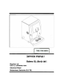
Service manua
Bolero XL (Blr42-001)
Bravilor Ltd.
Unit 15, Cordwallis Park
Clivemont Road
Maidenhead, Berkshire SL6 7BU
All rights reserved.
No part of this document may be copied and/or publiShedby means of printing, photocopying,
microfilming or by any other means whatsoever without the prior written consent of the manufacturer.
This applies equally to the included drawings and/or diagrams.
The Informationcontained in this document is based on general data concerning the construction, materials
characteristics and working methods known to us at the time of publication and therefore we reserve the
right to make changes without notice. For this reason the Instructionscontained in this document should be
treated as a guide to the installation, maintenance and repair, of the machine indicated on the front cover.
This document applies to the standard version of this machine. The manufacturer therefore accepts no
liability for any damage arising from specificationsthat deviate from the standard version of the
machine as delivered to you.
Every possible care has been taken in the production of this document, but the manufacturer accepts
no liabilityfor any errorsin this documentor for anyconseauences
arisinatherefrom.
TAKE THE TIME TO CAREFULLY READ THIS DOCUMENT BEFORE INSTALLING,
4Nn RFP4IRINt'. TWF U4t'.WINF
DURING READING KEEP THE FOLD-OUT OPEN.
ALWAYS KEEP THIS DOCUMENT NEAR THE MACHINE.
MAINTAINING
I
BRAVILOR
1<8>
Illj'hBONAMAT
PREFACE
Using this document
This document is intended to provide instructions for to safely install, maintain the machine.
The words "left". "right". "front" and "back" are used In this document to Indicate a particular part of the
machine. The point of departure here Is the position of the user standing at the operating side.
The position numbers 1.-23. used in this document refer to the figures in the fold-out. On this same
sheet the compositions 17. and 22. are specified In more detail. The further elaborated compositions4.
and 18. are dealt with in fig.2 and 3 respectively.
Icons and symbols
To the machine the following safety icons and symbols are applied.
t::. Procedures that can result In serious damage to the machine or in physical injury if they are not
carried out with due care.
In this document the following icons and symbols can be found:
I
[]],
.
~
IlE
-
Hint, suggestion or advice to carry out certain tasks more easily or neatly.
CAJJIK2N1
- Procedures that
can result in damage
to the machine,
the surrounding
area or the environment
if
theyarenotcarriedoutwithduecare.
WARNING
l1 Procedures that can result In serious damage to the machine or In physical Injury If they are not
carried out with due care.
Related documents
The following related documents are available:
- Supplementary sheet with factory settings
: 700.403.311
Documentcode
Document codes consist of two fields:
- Field 1: document number
- Field 2: revision date (if required followed by the revision number)
CCopyright Bravilor Bonamat B.V.
BravilorLtd. version
1.0
I
I
{I I BRAVILOR
'
1(8)
hIj IBONAMAT
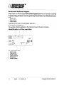
Service and technical support
Please contact our Technical SupportAfter Sales Support department for Information concerning
the specific setting, maintenance or service activities that fall outside the scope of this document. He
will always be happy to help you. When doing this, always ensure that you have the following details at
hand:
Model code
Type number
- Serial number
-
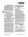
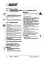
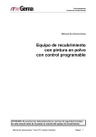
These data can be found on the identification plate (flg.1 ).
Guarantee conditions
The guarantee conditions applicable to this machine form part of the terms of delivery.
Identification
of the machine
Fig. 1 Identificationplate
1. Model code
2. Type number
3. Serial number
4. Output capacity
5. Frequency
6. Supply voltage
II
version
1.0 BravllorLtd.
CCopyright Bravilor Bonamat B.V.
Tableof contents
IIIIBRAVILOR@
III1 BONA MAT
I
I
I
I
I
II
II
II
VIII
VIII
VIII
VIII
VIII
VIII
VIII
IX
IX
IX
X
X
X
X
CCopyright Bravilor Bonamat B. V.
Bravilor Ltd.
V8f8ion
1.0
III
'BRAVILOR@
- - - - - - - --
'Ih
/11
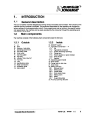
1.
Tableof contents
Introduction. . .. .. . . . .. .. .. . . . . . . . . . . . . . . . . . . . . . . . . . . . . . . . . . . . . . . . . . . . .
'
1.1
General description
1.2
Main components. .
1
1
1
1
1
2
2
2
2
2
2
2
2
2
3.
3
3
3
4
4
4
5
4. Operation.
"9.
I
4.1
VVlIU
VI. . . . . . . . . . . . . . . . . . . . . .
Controls
. . . . . . . . . . .. . . . . . . . . . . . . . . . . . . . . . . . . .
........
4.1.1
Operatingpanelfront
4.1.1
4.1.1.1
............................................................
4.1.1.1 Display
4.1.1.2
4.1.1.2 Buttonsandkeys...................................................
4.1.2
Operating
panel inside.
. . . . . . . . . . . . . .. . . . . . . . . . . . . . . . . . . . . . . . . . . . . . . .
4.1.2
4.1.2.1
control...................................................
4.1.2.1 Electronic
4.1.2.2
4.1.2.2 Keys on the electronic control
4.2
Dally use
........................................
4.2.1
Tapcup............................................................
4.2.3
Indicator 'drip-tray full'
4.2.2
4.2.4
5.
.........................................................
Maintenance
5.1
Dally
5.1.1
Tapping
mug,halfa jug or whole jug
...................................
...............................................
Raisingthemachine.................................................
by
users
with
limited
authority.
....... . .. ............
.............................................................
General...........................................................
Checking
the supply in the ingredients
container.
. . ..... ...... ..........
5.1.3
Cleaning...........................................................
5.1.3.1 Rinsingprogramme.................................................
5.1.3.2 Cleaningthe mixingsystem ..........................................
5.2 Weekly. . . . .
...v
...........................................................
5.2.1
General
Cleaningoutside
,.
5.2.2
Cleanin!
Cleaningthe mixerandthe supportingplate.
.
.
.
.
..
.
.
.
.
......
5.2.3
Cleanin!
plate
Cleaningingredientscontainer. . . . . . . . . . . . . . . . . ... ..
. .....
5.2.4
Cleaninj
5.1.2
IV
version
1.0 Bravllor Ltd.
5
5
5
5
5
5
5
6
6
6
6
6
7
7
7
7
7
7
8
8
8
8
8
9
CCopyrIght Bravilor Bonamat B.V.
I
Table of contents
.
BRAVILOR(ji)
///hBONAMAT
'~,'
..~.--
-cc-
~"-
.
~~.
-'~
.
6. Use of the programming unit
6.1
......
Reading counter positions of tapped drinks .............................
Readingcounterpositionsperdrink
...................................
nelOemngmel,;uununpuIOIUUn51UZerU.................................
Reading
6.1.1
6.1.2
out the counter
contents
or re-settlng
the counter.
...
C.I."
6.1.3
Resettingthe counterpositionsto zero. ................................
6.2 Setting possibilities. . . . . . . . . . . . . . . . . . . . . . . . . . . . . . . . . . . . . . . . . . . . . . .
7.
..................................
6.2.1
Setting the amount of water per drink
6.2.2
6.2.2.1
6.2.2.2
6.2.2.2
Switchingon or off the tappingpossibilities'mug,halfa jug or wholejug' ...
Switchingoff ."""""""""""""""""""""""""""
Switchingon .......................................................
6.2.3
Settingstrongnessofdrink ...........................................
6.2.3
6.2.4
Setting the hot water temperature. . . . . . . . . . . . . . . . . . . . . . . . . . . . . . . . . . . . .
6.2.4
6.2.5
Settingdescalingsignal..............................................
6.2.5
aintenance
ntenanceby authorized users.
users . . . . . . . . . . . . . . . . . . . . . . . . . . . . . . . .
Mai
.........................................................
.............................................
Descaler
Desea
7.1
7.2
Cleaning
Cleanl the exhaust fans.
perating principle.
8.
. . . . . . . . . . . .............................
.............................................
Operating
8.1 Operation
Opera' general.
general . . . . . . . . . . . . . . . . . . . . . . . . . . . . . . . . . . . . . . . . . . . . . . . .
Operating
system.
................................................
8.2 Opera'
system.
.........................................
8.3~~Water
Water
Water
system.
~ ~
.' .. .. .. .. .. .. .. .. .. .. .............
8.3.1
8.3.1.1
8.3.1.2
8.3.1.2
8.3.1.3
8.3.1.3
8.4
8.5
8.6
9.
Protection........................
Boiling
pre
Boilingprotection
.................
Overflow
Overflow
~
protection.
. .............
Boiling dl)
dry protection. . . . . . ........
Boiling
Dosing. . . . . . .
Water selector
Mixing system
system ...................
Mixing
8.6.1
Ingredient
container.
container . . . . . . . . . . .
8.6.1
Ingredient
- - -.. .
8.6.2
Mixingunit....................
aintenance by service technicians
Ma
9.1
9.2
.......................
Hygiene
Preventive
maintenance
general
9.2.2
Interior. . . . .
9.2.3
Watersystem
Six-monthly maintenance. . . . . . . . . . . . . . . . . . . . . . . . . . . . . . . . . . . . . . . . .
9.3
Bolero XL
10. Exploded
10.1
10.2 Electrical parts
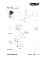
10.3 Mixing system
Water system.. . . . . . . . . . . . . . . . . . . . . . . . . . . . . . . . . . . . . . . . . . . . . . . . . . . . .
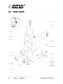
10.4 Water
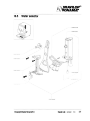
Water selector
10.5 Water
:tric diagrams
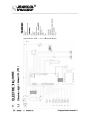
11. Electric
11.1 Electric diagram Bolero XL (STD) ..
11.2 Electric diagram Bolero XL (IRUGB) . . . . . . . . . . . . . . . . . . . . . . . . . . . . . . .
CCopyright Bravilor Bonamat B.V.
Bravilor Ud.
version
1.0
10
10
10
10
10
10
10
11
11
11
12
12
13
14
14
15
16
17
17
17
17
17
17
18
18
18
19
19
19
20
20
20
20
20
20
20
21
21
22
23
24
25
26
26
27
v
I
BRAVILOR,(8)
///hS ONA MAT
12. Repair work.
12.1 Operating
12.1.1
Table of contents
. . . . . . . . . . . . . . . . . . . . . . . . ............................
system. . . . . . . . . . . . . . . . . . . . . . . . . . . . . . . . . . . . . . . . . . . . . . . . .
Exchangingthekeyboardprint........................................
12.2 Water system. . . . . . . . . . . . . . . . . . . . . . . . . . . . . . . . . . . . . . . . . . . . . . . . . . . . . .
12.2.1 Draining
ofthewatersystem.. . . . . .
12.2.1
12.2.2
Exchanging the measuring basin. . . . . . . . . . . . . . . . . . . . . . . . . . . . . . . . . . . . . .
12.2.2
12.2.3 Exchangingthe flow boiler ...........................................
12.2.3
12.2.4 Exchangingthe NTCresistor .........................................
12.2.4
Siphoning basin I water selector. . . . . . . . . . . . . . . . . . ....................
12.2.5
12.2.5.1
Exchanging the siphoning basin I water selector.
. . . . ... .... . ....... .. ..
12.2.5.1
12.2.5.2Descalingofthewaterselector
12.2.5.2
....
..............
.......................................
12.2.6
Exchanging
12.2.7
Exchanging the light sensor
12.2.8
the water selector
motor.
..............
12.3 Mixingsystem
12.3.1
. . . . . . . . . . . . . .. .
::.................
Exchangingthe connectingwireto the lightsensor ......................
Exchanging
t"'
~
~........
the ingredient
container
motors.
........
...................
12.3.1.1 Exchangingmotor1 .................................................
12.3.1.2 Exchangingmotor20r3 .............................................
12.3.1.3Exchanging
motor4 .................................................
12.3.2
12.4
Exchanging
Miscellaneous
12.4.1
the mixing unit motor.
components.
12.4.3
..........
Exchanging the transformer
12.4.2 Exchanging
the solid
Exchanging
. .. ....... .. .. ...... .......
,;
.
..........................................
state relay
the exhaust
....................................
fan motor.
.......
. . . . . . .............................
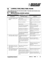
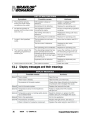
13. Correcting malfunctions. . . . . . . . . . . . . . . . . . . . . . . . . . . . . . . . . . . . . . . . .
13.1
Malfunctioning
analysis
general.
........
...... ........ ... .... ... ..
13.2 Displaymessagesand their meanings.. ............................
............................
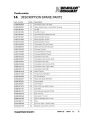
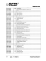
14. Description spare parts. . . . . . . . . . . . . . . . . . . . . . . . . . . . . . . . . . . . . . . . . .
15.Specialcodes...................................................
15.1 Resetting the daycounters to zero. . . . . . . . . . . . . . . . . . . . . . . . . . . . . . . . .
15.2 Resetting the total counters to zero. . . . . . . . . . . . . . . . . . . . . . . . . . . . . . . .
15.3
Interrupt
the
descaling
programm
. . . .. . . . . . . . . . . . . . . . . . . . . . . . . . . . . .
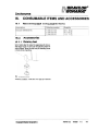
16. Consumable Items and accessories. . . . . ..
. . . . . ..
. . . . . ..
. . . . . ..
. . . . ..
. . . ..
. .. .
16.1
Recommended
consumable
items.
. . . . . . . . .. . . . .. . . . . . . . .. . . . . . .. .
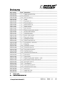
16.2 Accessories......................................................
......................................................
17.
17.1
17.2
VI
............................
outlet. . . . . . . . . . . . . . . . . . . . . . . . . . . . . . . . . . . . . .
version
1.0 Bfavllorltd.
CCopyright
Bravilor
41
41
41
41
42
42
43
Bonamat B.V.
~
Fig.
1 Identification
Fig.
2
Operating
plate.
panel
front.
. . . . .
. . .
.......................
....................
........................ .................
............
....................
. . . . . . . . . . . '.
............. ... .............. ........ .......
. . . . . . . . . . . . . . . . . . . . . . .. .. ...... . . . . . . . . . . . . . . . . . . . . . . . .
~
Fig.3 OperatingpanelInside
Fig.
4 Flushing
programme.
. . .
. ................. .. .................. ...... ........... .
Fig.5 Mountingthe mixer
Fig.6 Counterpositions
Fig. 7 Initial
situation
programming.
Fig.8 Settingtheamountof drink
Fig. 9 Initial situation programming
...........
.................
,
. . . . , . . . . . . . . . '.. . . . . . . . . . . . . . . . . . . ..................
.. . . . . . . . . . .. . . ,
"",
,
,
,.
,
.................
,...
. .
...
... ...
,
.....
.................
Fig. 10 Strongnessdrink
.............
Fig. 11Temperaturesetting
,.........................................
Fig. 12 Descalingsignal"""""""""""""""""""","""""'"..........
Fig. 13 Descalingsignal
,....................................
Fig. 14 Descalingprogramme
',
..............
Fig. 15 Removingthe fan grille
Fig. 16 Removing
the fan blade.
. . . . . . . . . . . . . . .. . . . . . . . . . . . . . . . . . . . . . . . . . . . . . . . . . . . . . . .
II
5
5
7
8
10
11
11
12
12
12
13
14
14
15
15
18
18
41
.........................................................
.................
Fig. 17 Operating principle water system. . . . . . . . . . . . . . . , . . . . . . . . . . . . . .. . . . . . . . . . . . . . . . . .
......................
Flg.18Waterselector.................................................................
Fig.19Raisingfoot
........................
:....................................
....................
CCopyright Bravilor Bonamat B.V.
Bravilor Ltd.
version
1.0
VII
(ii)
I BRAVILOR
//1BONAMAT
Safety instructions
instructions and
and danger
danger warnings
warnings
General
The manufacturer accepts no liability whatsoever for damage or Injury resulting from a failure to
(strictly) observe the safety instructions contained In this document or resulting from negligence during
the installation, maintenance or repair of the machine specified on the front cover of this document or
of any related accessories.
Additional safety instructions may be required, depending on the specific working conditions required
for the accessories used. Please contact the After Sales Support department if you think there may be
any potential danger during installation, maintenance or repair of the machine.
Service Manual
.
Each person working with the machine should know the contents of this document and carefully
follow the Instructions contained. The management must Instruct the personnel on the basis of this
document and take all the instructions and recommendations into account.
. Never alter the order in which the actions are to be done, and strictly follow the instructions set out
in these manuals.
.
Always keep this document In a safe place.
Icons and instructions on the machine (if present)
.
Icons, warnings and instructions attached to the machine form part of the safety provisions. They
must not be covered or removed and they must be present and remain legible throughout the life of
the machine. Any icon, warning or instruction that becomes illegible must be repaired or replaced
immediately.
Maintenancetechnicians
. Repairs to the machine, as well as installation and maintenanceactivities denoted as such, may
only be carried out by properly trained and qualified maintenancetechnicians. They are at all times
fully responsible for observing the local safety instructions and regulations when carrying out their
maintenance duties.
Technical specifications
The specifications given in this document may not be modified.
Modifications
Modification of (parts of) the machine is not allowed.
VIII
version
1.0 Bravilor Ltd.
CCopyright Bravilor Bonamat B.V.
/BRAVILOR@
~j BONA MAT
Installation
. The maximumacceptableambienttemperaturewith which a goodoperationcan be guaranteedIs 4O"C.
. Considerdamagecausedby freezing.Neverplacethe machinein roomsIn whichthe temperature
can drop belowO°C.Afterall, with normalusetherewill alwaysbe waterin the machine.
. Do not tum overthe machine,moveit upright.
. Neverinstallthe machinein placeswherewateris sprayedor sprinkled.
. Neverinstallthe machinein frontof entrances,exitsor passagewaysintendedfor emergency
services.
. Place the machine on a sufficiently solid, flat surface close to a water connection, water discharge
and an earthed electrical power outlet.
. Connect the machine to the electrical supply In such a way that the power can easily be
disconnected.
. Leave sufficient space at the back and front of the machine for maintenance and repair purposes.
Leave a space of at least 5 cm at the left and right sides of the machine for ventilation.
Connect the machine to a readily accessible, manually operated water tap, so that the water supply
can easily be turned off.
. Always observe local rules and standards when installing this machine.
.
.
Use
.
Inspect the machine before use and check for damages.
. Protect the machine against water and moisture. Do not wet the machine by spraying and never
submerge the machine in water.
Keep the operating controls free from dirt and grease.
Note that during use some parts of the machine become very hot.
. Disconnect the electricity grid and the water supply when the machine will not be used for a longer
period. Clean the machine following the instructions in chapter 5. Make sure that no ingredients are left
in the ingredient containers. Discharge the water (chapter 7.).
. Components that need lubrication and come into contact with the drink may only be lubricated with
silicone grease suitable for food products.
.
.
Service, maintenanceand repairs
,Ill!
I
-Repair activities may only be carried out by qualified maintenance technicians. Also, a distinction
is made in this document between the following maintenance actlvltle..
A. maintenance activities that may be carried out by the dally user;
B. maintenance activities that may only be carried out by specially trained users with extended
qualifications;
C. maintenance activities that may only be carried out by authorised service technicians.
If the mains lead is visibly damaged, it has to be replaced by a qualified service technician.
Observe the given maintenance Intervals. Overdue maintenancecan lead to high repair costs and
may cause guarantee claims to become invalid.
Do not carry out any maintenance or repair activities concerning the machine before having it
protected against unintentional coming into operation. In such cases disconnect the electricity grid.
Avoid contact with moving parts.
Never leave the machine during maintenance activities.
. Only use tools, parts, materials, lubricants and service techniques that are approved by the
manufacturer. Never use worn tools and do not leave tools in or around the machine.
For cleaning the machine only use descaler recommendedby the manufacturer.
. Always wear suitable facial protection and gloves while working with descaling materials. Wash your
hands after using these materials.
.
.
.
.
.
.
CCopyright BtavlIor Bonamat B.V.
Bravilor Ud.
version
1.0
IX
1111BRAVILOR
1<8>
IIIIBONAMAT
. Prevent damage of the machine caused by spilled descaler solution. Remove spilled solution as
quickly as possible and follow the previously mentioned safety instructions.
. Safety provisions that were removed for the purpose of service. maintenance or repair, have to be
reinstalled and checked for correct functioning immediately after these activities have been carried out.
Safety devices present
The machine is defauh provided with the following safety devices:
- Using the ON/OFF-swltch the machine Is switched on or off. After switching off there is still some
residual vohage in the electrical system. Remove the plug from the wall outlet In order to take away
this residual vohage.
- Electricalfuse of electronic components that is activated as soon as the power drop exceeds the
allowed maximum value due to a power failure.
- Thermal safety device that interrupts the power when the water temperature in the boiler becomes
too high.
- Boiling protection that interrupts the power when the boiler temperature becomes too high.
- Overflow Drotectionthat Dreventsthe machine from takina in more water than allowed.
Emergency stop to interrupt a selection of the amount of fluid (cup, half a can or whole can). The
-
.
t'vt'IA
-
CttArtAli IACtt let finiCthAli
Drlp-tray with float indication and discharge possibilitiesto prevent trouble caused by spilled drink.
Machines and the environment
Packagingmaterial
The main components of the packaging material for transport and protection of the machine are the
following:
- Corrugated board
- Polystyrene elements
Generally,the packaging material can be returned through your dealer after installation of the machine.
If this Is not be possible, ask your local authority refuse department how you can dispose of the
materials.
Disposal of the machi ne
Machines that you wish to dispose of can usually after consultation be returned to your dealer. If this is
not possible. inquire with your local authority about the possibilities for re-use or
environmentally-friendly processing of the materials. All plastic parts have been clearly coded for this
purpose. The printed-circuit board in the machine and the components connected to this should be
consigned to electrical or electronic refuse.
x
V8fSion
1.0 Bnivllor Ltd.
CCopyright Bravilor Bonamat B.V.
I
111I
1.
INTRODUCTION
1.1
General description
BRAVILOR
I@
BONAMAT
This is a hot drinks machine designed for serving various hot drinks and hot water. The functions of the
machine are fully computer--controlled.The personnel responsiblefor the operation can change the
factory settings in the programmable control. Once programmed and set conform the specific wishes
and requirements,the machine can be easily operated by the consumer through the operating panel
(with display) at the front.
1.2
Main components
The machine consists of the following main components (see the fold out):
1.2.1
Outside
1. Ud
2. Door
3. Window + text plate
4. Operating panel front
5. Hot water outlet
6. Drink outlet
7. Drip-tray plate
8. Drip-tray
9. Indicator 'drip-tray full'
10., Foot(4x)
11. Lock
12. Identification plate
13., Water connection
14., Ventilation grille
15. Mains cable
,
,
CCopyright Bravilor Bonamat B.V.
1.2.2
Inside
16. ON/OFF switch
17. Ingredient containers 1 - 4
17.1 Ud
17.2 Ingredients container
17.3 Outlet (discharge opening)
17.4 Fixing earn
17.5 Worm (plastic) or spiral (metal)
17.6 Drive clutch
17.7 Agitator
18. Operating panel inside
19. Drink outlet
20. Fixing hole for drip tray
21. Drain hose
22. Mixing unit (2x)
22.1 Exhaust hood
22.2 Mixing basin
22.3 Outlet piece
22.4 Drink outlet hose
22.5 Mixing room
22.6 Mixer
22.7 Supporting plate
23. Pouring opening descaler
Bravilor Ltd.
version
1.0
1
IIII BRAVILOR@
IIIIBONAMAT
2.
TECHNICAL DATA
2.1
Gen«
General
Model
: Blr42-OO1
Weight (empty)
(empty)
: 14 kg
2.2
.
See the fold out.
2.3
.
DimE
Dimensions
Electrical system
Elec1
See the Identificationplate for the correct values.
2.4
Water system
Water hardness
Min. water pressure (supply)
Max. water pressure (supply)
Flow-rate
Conductivity
Boller capacity
Hour capacity (hot water)
2.5
: min. 5 °dH
: 100 kPa (1 bar)
: 1000 kPa (10 bar)
: 2 Vmin
: ~ 35 ~ Siemens/em
: 1 liter
: 20 liters per hour
Capacity
Start-uptime
Deliverytime per cup (120ml)
2.6
Environmental
: 2 minutes
: 6 seconds
conditions
In view of danger of freezing the machine may never be placed in rooms where the temperature can
fall below COCo
2.7
Recommended descaling materials
Descaler
: RENEGITE
CAlJIK2N.l
- Before use first read
the
[]]~first
read
the instructions
inBtruclior on the packing.
See chapter 16. for ordering descaler.
2.8
2
Type subjects
version 1.0 BtavllorLtd.
CCopyrIght Bravilor Bonamat B.V.
BRAVILOR@
IIIIBONAMAT
.
I
-"-
I
.
.
I
INSTAllATION
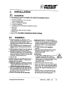
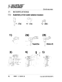
3.1
Unpacking
. Check whether the machine is complete. The contents of the packaging consist of:
---
-
.
1 hot drinks machine
1 driJ:Hray (complete with drip-tray plate)
1 water connection hose
1 sachet of RENEGITE descaler
1 funnel (for descaling)
1 scrubbing brush for cleaning the ingredients container
2 door keys
1 glass jug
supplementary sheet with factory settings
This manual
Please contact your dealer if components are missing or damaged.
3.2
Installation
. Place the machine on a flat (max. 5° off
plumb), sufficiently solid surface near a water
connection point (and if possible a water
discharge) and an electricity connection point
that Is earthed.
Leave sufficient space for maintenance and
repair purposes at the back and front of the
machine.
.
. Leave a space of at least 5 em at the left and
right sides of the machine for ventilation.
. Connect the machine to a readily accessible
.
.
manually operated water tap, so that the water
supply can easily be turned off. Use the water
connection hose provided for this.
Open the tap.
. Removethe cover(17.1)
. Put back the cover on the ingredients
container.
. Also fill the other containers with the correct
ingredient, according to table 3 on the
supplementary sheet.
WABNJN.G.
.
.
Remove the window and the name plate.
. Place the multilingual, double-sided leaf with
.
drink names behind the name plate. Now you
can read the drink names in the required
language through the openings.
Remount the window with the name plate.
@CopyrlghtBravllor Bonamat B.V.
of the 1 sl ingredients
container. Fill the ingredients container with the
ingredient especially meant for this machine,
according to table 3 on the supplementary
sheet.
Open the door (2.) on the left side with the key.
Follow the instructions below to Install another
language with drink names:
. Remove the window (3.) with the name plate.
- Press the plastic lips of the window from the
inside of the machine to the outside.
-
. Swing up the cover (1.) of the machine.
.
D. Power supply voltages vary from one country
to another. Ensure that the machine is
suitable for connecting to the local power
supply. Details on the required supply voltage
and frequency can be found on the
identification plate.
Connect the plug to the power socket.
Switch the machine on by turning the ON/OFF
switch (16.) to ON. A little red square appears
on the switch. The machine starts filling up with
water. On the display all fields light up for a
moment).
Close the cover (1.) and close the door (2.)
with the key. When the water is hot enough,
the flashing thermometer disappears.
Bravllor Ltd.
version
1.0
3
~
1111BRAVILOR@
IIIIBONAMAT
~
IJE
- It is possible to mount a discharge hose on
.
the drip-tray. At the back of the drip-tray
there is a spout. Bore a hole in this and slide
the hose on.
Hook the fixing cam of the drip tray into the
fixing hole (20.).
3.3
~~
L!.J
Initial use
3.3.1
Drink system
.
Place an empty cup under the drink outlet (6.).
. Press the Selection button of the drink to be
tested.
- The selection is confirmed by a beep. Only
the dot on the display at the selected drink
remains after which the drinks flows into the
cup. During the filling the cup on the display
flashes.
Throwaway the content of the first two cups.
. Check for the 3rdcup whether the taste and
the amount are right. If not, correct the taste
and/or amount (§6.2).
Repeatthe abovesteps for the other drinks.
.
machinebeforeuseand checkfor
damages.
- Protect the machine against water and moist.
Do not wet the machine by spraying and
never submerge it in water.
- Keep the operating controls free from dirt and
grease.
- Note that during use some parts of the
machine become very hot.
At coming into operation the machine has the
default factory settings. If required, these settings
can be adjusted (chapter 6.).
.
3.3.2
.
.
Hot water system
Place an empty cup under the hot water outlet
(5.).
Press the Selection button (4.10) 'hot water'.
- The selection made is confirmed by a beep.
Only the dot on the display at the selected
drink remains after which the water flows
into the cup. During the filling the cup on the
display flashes.
The system is now ready for use.
4
version
1.0 BravlIor Ltd.
CCopyright Bravilor Bonamat a.v.
IIII BRAVILOR
(jj)
IIIIBONAMAT
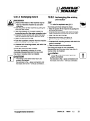
4.
OPERATION
4.1
Controls
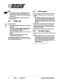
4.1.2
Operating panel inside
The machine is provided with two operating
panels, one at the front (flg.2 ) and one at the
Inside (fig.3 ). During normal daily use of the
machine by the consumer, only the operating
panel at the front is used. For programming and
specific activities the operating panel at the Inside
is important as well.
4.1.1
Operating panel front
4.4~
. 8.-4.8
. 1... . e..J:J . e.- 4.8
.
. .-- 4.8
4.~
.gJJo... .,---4.10
4.1
.
4.2---8
4.3--.8
4
4.7
ill
4.13
4.12 4.11
Fig. 2 Operating panel front
4.1.1.1 Display
. The display (4.) shows during normal use while
programming, rinsing or descaling the machine
and in the case of failuresvarioussymbols,
values and messages that will be explained in
this manual. Rg.2 displays the basic position
(operational position).
4.1.1.2 Buttons and keys
4.1- 4.9
Selection buttons for various hot
drinks
4.10
Selection button 'hot water'
4.11
Setting key [>]
4.12
Enter key (blocked during normal
use of the machine)
4.13
Setting key [<]
The setting keys (4.11 and 4.13) have more than
one function. During normal use of the machine
these keys are only used to choose between cup,
mug, half a jug and whole jug respectively).
The [Enter] key (4.12) Is blocked during normal
use of the machine.
CCopyright Bravllor Bonamat B.V.
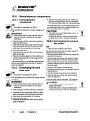
Fig. 3 Operating panel inside
4.1.2.1
Electronic
control
The housing of the electronic control with
operating panel (18.) of the machine is found at
the inside of the door (2.). The two keys are for
service and maintenance activities.
4.1.2.2 Keys on the electronic
control
18.1 Key 'rinse'
18.2 Programming key
While the machineis in use,the factorydefault
settings may appear to be incorrect or insufficient
for the situation in which the machine is used.
These settings can be adjusted following the
instructions In §6.2.
The present chapter (4.) therefore only describes
the normal daily use of the machine.
Periodic maintenance by users with limited
authority is described in Section 5.
Bravilor Ud.
version
1.0
5
BRAVILOR@
if) B ONA MAT
I
4.2
Daily u
. Switch the machine on with the ON/OFF
switch (16.) under the cover (1.). When the
machine is on there is a little red square visible
on the switch. During waRning up a flashing
thennometer appears in the upper right comer
of the display. Tapping is only possible after the
thermometer has disappeared from the display.
4.2.1
4.2.1
Tap cup
You can only select those drinks that are
indicated on the display by a black dot.
. Place an empty cup under the drink outlet (6.).
. Select a drink with one of the selection buttons
(4.1- 4.9).
- The selection made is confinned with a
beep. On the display only the dot with the
selected drink remains after which the drink
flows
into the cup. During the filling the cup
, flasheson the display.
4.2.2
Tapping mug, half a jug
or whole jug
IIE!
- By pressing any selection button after having
selected a mug, half a jug or a whole jug you
prevent the machine from really executing
this task. The machine is now limited to
tapping just one cup.
4.2.3
Indicator 'drip-tray full'
The float indication (9.) will come up at reaching
the maximum level of spilled drink. In this case,
empty the driJHray as soon as possible!
4.2.4
Raising the machine
When you use a mug or jug that doe. not fit
under the drink outlet you can temporarily
remove the drip-tray.
If necessary,the machine can be raised 2 em
with a set of raising feet to increase the distance
between the drink outlets and the dri(:Hray. Such
a set can be ordered as accessory with your
specialist (§ 16.2.1 ).
DE
.
- After5 secondsthe settingautomatically
returnsto tappinga cup.
- Tappinga half or wholejug is not possible
for ell drinks (thisdependson the typeof
the machine)
Select with the setting key (4.11 or 4.13) mug,
halfa jug or wholejug.
~
IlE!
- If a thermometer appears on the display the
temperature is (temporarily) too low caused
by tapping too much water. The machine is
blocked until the temperature Is right again.
. Place an empty mug or jug under the drink
.
6
outlet (6.).
Select a drink with one of the selection buttons
(4.1 - 4.9).
- The selection made is confirmed with a
beep. On the display only the dot with the
selected drink remains after which the drink
flows into the mug or jug. During the filling
the cup flashes on the display.
version
1.0 Bravilor Ltd.
CCopyright Bravilor Bonamat B.V.
IIII BRAVILOR@
IIIIBONAMAT
5.1.3.2 Cleaning the mixing system
.
Weekly
Remove the drip tray (8.).
.
5.2.1 General
Open the door (2.).
.
Tilt the ingredient containers a bit slantingly
backwards and lift them out of the machine.
.
Pull the mixing basin (22.2) towards you, so
that the exhaust opening of the exhaust hood
(22.1) is released and subsequently move it
back and forth to remove the exhaust hood.
. Pull the mixing basin (22.2) carefully loose
from the water connection and remove it by
moving it back and forth.
. Pull the outlet hose (22.4) carefully loosefrom
the mixing room (22.5).
. Turn the outlet piece (with hose) (22.3) a
quarter of a turn into the direction of the
machine and then move it upwards. so that it is
loosened from the drink outlet.
.
Remove
the mixing room (22.5) by turning
it to
the right and after that pulling it towards you.
Repeat this procedure for the other mixing unit.
.
.
Wash all components in hot water with a
normal washing-up liquid.
. Remount all parts in reversed order.
~
5.2
WAf1fll1m
WABNlfm
-
Turn the outlets apart; they should almost
(j:1 mm) touch the side of the mixing basin.
The following activities must be carried out
weekly:
5.2.2
Cleaningoutside
. Remove the drij:Hray (8.).
. Wash all part of the drip-tray in hot water.
. Clean the outside of the machine with a moist
cloth. If necessary use a non-scratching or
no~orrosive cleaning product.
After this dry the machine with a soft cloth.
. Place the drip-tray (8.) in front of the machine
again.
.
5.2.3 Cleaning the mixer and
5.2.3
the supporting plate
. Carry out the first 8 steps of §5.1.3.2.
. Remove the mixer (22.6) from the mixer motor
shaft by pulling it perpendicularly from the
shaft.
Remove the supporting plate (22.7) by turning
it to the right and after that pulling it towards
you.
. Repeat this procedure for the other mixing unit.
. Wash all components in hot water with a
normal washin<HJDliQuid.
.
. Remountall partsin reversedorder.
IlE
- At mounting the mixer in the mixer motor
shaft the dot (fig.5 ) must be in line with the
flattened part of the mixer motor shaft.
"
Fig. 5 Mounting the mixer
8
version
1.0 Bravllor Ltd.
CCopyright Bravilor Bonamat B. V.
1111BRAVILOR@
IIIIBONAMAT
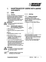
MAINTENANCE BY USERS WITH LIMITED
AUTHORITY
5.1
5.1.1
Daily
General
Obviously, the machine and the accessories must
be carefully kept clean. Besides, it should be
checked dally whether there are still sufficient
ingredients In the ingredient containers.
. Remove the drip tray (8.) complete and wash
all components in hot water with a normal
washing-up liquid.
[Ii\.
. ~
)
5.1.3
Cleaning
5.1.3.1 Rinsing programme
The machine is uitgerust met een
spoelprogrammavoor hat reinigen van de
mix-units. Aanbevolen wordt om dit programma
dagelijks te gebruiken.
. Place a jug under the drink outlet (6.).
Press key (18.1) at the inside of the door.
.
" the descalorsignalappoorsin
the display (fi9.13 ).
5.1.2
Checking the supply in
the ingredients container
. Openthe door(2.) with the suppliedkey.
. Liftup the cover (1.).
. Check the contents of the ingredient containers
(17.).
up:
.FIlling
Lift the ingredients container (17.) a bit
slantinglybackwardsout of the machine.
. Removethe cover(17.1).
. Check whether the ingredients have not
congealed. If this is the case, clean the
ingredients container (§5.2.4).
. Fill up the corresponding ingredient, see
supplementary sheet table 3 .
.
~
A flashing cup appears on the display to indicate
that the rinsing programme is active.
. Repeat the rinsing by pressing the key (18.1)
again until the water coming out of the drink
outlet piece is clean.
Close the door with the key and place the
driJHray in front of the machine again.
.
Press the cover on the container and place this
back into the machine. Make sure that the
drive clutch (17.6) at the back side of the
container Is slid over the drive shaft in the back
wall and that the fixing eam (17.4) at the
bottom falls into the notch of the sheeHTletal
work.
WARNING
~ The ingredient containers and their places in
the machine are numbered. Always stick to
the order of the numbers.
he ingredients container can also be filled
'ithout taking it out of the machine.
CCopyright Bravilor Bonamat B. V.
Bravilor Ud.
version
1.0
7
fIll BRAVILOR@
////BONAMAT
5.2.4
Cleaning ingredients
IIE
container
- Check before using the machine again
whether all parts have been mounted
correctly:
- Are the ingredient containers (17.) at the
right place and is the fixing cam (17.4) at
the bottom side of the notch of the
sheet-metal work?
.
.
Lift the ingredients container slantingly
backwards out of the machine.
Remove the cover (17.1).
. Shake the ingredients out of the container into
a clean dry bowl.
. Takethe outlet(17.3)away.
. Remove with the supplied scrubbing brush the
remnants from the ingredients container, from
the worm (or spiral) (17.5) and from the outlet.
~
- If necessary,the large nuts at the front and at
the back can be loosened. The loose
components can be cleaned with hot water.
VNWABNING
,
A If you clean
water,
.
.
.
- Havethe outletpieces(17.3)of the
.
ingredient containe~sbee~ ~Iace~ correctly
above the left and right mixing units?
Reflush the mixing units (§5.1.3.1) because
ingredients may have fallen into the mixing
TIP
.
~
make
.
units during placing the ingredient containers.
Close the door (2.) with the key and place the
drip-tray (8.) in front of the machine again.
the ingredients
container
with
sure that all parts are very dry
before you fill the ingredients container again.
This prevents encrusting.
Fill up the corresponding ingredient, see
supplementary sheet table3 .
Press the cover (17.1) and the outlet (17.2) on
the ingredients container (17.) and on the
correct place back into the machine. Make
sure that the drive clutch (17.6) at the back
side slides over the drive cam in the back wall.
Make sure that the fixing earn (17.4) at the
bottom falls into the notch of the sheet-metal
work.
Repeat this procedure for the other ingredient
containers.
@Copyrlght Bravilor Bonamat B.V.
Bravilor Ltd.
version
1.0
9
,BRAVILOR(iJ)
//1
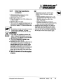
6.
USE OF THE PROGRAMMING UNIT
The machine is provided with a programme with
which you as user can read data and set the
machine in accordance with your personal
6.1.2
requirements.
. Select the desired drink with one of the
6.1
Reading out the
counter contents or
re-setting
ng the count
counter
. Press the programming button (18.2) to start
the programming.
Readingcounter
positions per drink
selection buttons.
. Select with the setting key (4.11 or 4.13) cup.
mug, half a jug or whole jug.
. Read the counter positions; a black dot on the
display indicates the selected drink.
6.1.3 Resetting the counter
positions to zero
. Select any drink with one of the selection
buttons.
. Keep the button pressed down during 5
seconds.
operation
The counter for all drinks IS reset to zero for
cups. mugs, half jugs and whole jugs.
Ill!
- It is not possible to reset the total counter
of the machine to zero!
. Press the programming button (18.2) to return
to the base position of the display.
6.2
Setting possibilities
DE
- All changes can be entered consecutivelyat
Iter positions
6.1.1
once, because they succeed each other.
- The following parag!aphs d~~~be the
procedures per setting possibility, i.e. not
Reading counter
consecutively.
positions of tapped drinks 6.2.1
th the
. Select with
the setting
setting key
key (4.11
(4.11 or
or 4.13)
4.13) cup.
cup.
.
mug. half a jug or whole jug.
Read the counter positions.
Setting the amount of
water
water per
per drink
At setting the amount of water per drink it should
be taken into account that the actual amount of
drink Is more than the amount of water that is
set. This is because ingredients are added to the
hot water. This particularly happens when tapping
a chocolate drink.
WM1fJJ/Kl
Keep this in mind in order to prevent trouble
with cups, mugs and jugs running over.
. Press the programming button (18.2) to start
the programming.
Press one time on the [Enter] key (4.12).
l:1
.
10
V8fSion
1.0 Bfavllor Ltd.
CCopyright Btavilor Bonamat B. V.
~
"
I ' BRAVILOR@
"j 'BONAMAT
6.2.2
Switching on or off the
tapping possibilities 'mug,
half a jug or whole jug'
If the machine has been set to paid delivery,
tapping a mug, half a jug or a whole jug is lH21
possible.
6.2.2.1
Switching off
. Decrease the value set for 'mug' to the
programming
.
minimum (§6.2.1). The display shows 'OFP.
Now the tapping possibilities for a mug is
switched off. When in use selecting 'mug' for
the drink Involved gives no dot on the display;
this choice is not possible then.
This tapping possibility can be switched off in the
same way for all drinks.
. Press the programming key (18.2) to finish the
programming.
6.2.2.2
Switching on
. Increase the set value for 'mug' (§6.2.1). The
display again shows the value that you are to
set in ml. Now the tapping possibility for a mug
is switched 00.
This tapping possibility can be switched on in the
same way for all drinks.
. Press the programming key (18.2) to finish the
programming.
.
DE
-
By pressing the setting key (4.11 or 4.13)
longer you quickly to through the range.
- See table 4 on the supplementary sheet for
the factory settings and the (im)possibillties.
- Write your own settings with a pencil in the
table.
. Press the [Enter) key (4.12) for setting the
values for a mug.
. Press the [Enter) key (4.12) for setting the
values for half
8 jug.
. Press the [Enter) key (4.12) for setting the
values for a whole jug.
. Press the programming button (18.2) to finish
the programming.
CCopyright Bravilor Bonamat B.V.
Bravilor Ltd.
version
1.0
11
I BRAVILOR (jj)
BONAMAT
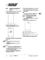
6.2.3
Setting strongness of
drink
. Press the programming key (18.2) to start the
programming.
. Press one time the [Enter] key (4.12).
.
Now set with the setting key (4.11 or 4.13) the
strongness of the next ingredient container.
. Press the programming key (18.2) to finish the
programming.
DE
-
The machine automatically relates
relates the set
percentage to the set amount of water.
6.2.4 Setting the hot water
temperature
. Press the programming key (18.2) to start the
programming.
. Pressthreetimesthe [Enter]key (4.12).
. Pressfive times the [Enter] key (4.12).
.
.
The factory setting of the machine is 85°C.
The ingredient containers of the machine appear
on the screen.
DE
- The Ingredientcontainerthat can be set
flashes.
. Set with the setting key (4.11 or 4.13) the
strongness.
'rite down your own settings with a pencil in
Ie table on the supplementary sheet.
Press several times the Enter key (4.12) to set
the other ingredient containers.
The number of ingredient containers to be set
depends on the selected drink, see table 4 on
the supplementary sheet.
12
version
1.0 Bravllor Ltd.
CCopyrIght Bravilor
Bonamat B. V.
IIII BRAVILOR@
IIIIBONAMAT
~
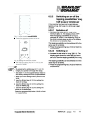
6.2.5
~
t
e
J,
I ,I
,("
.
Setting descaling signal
.
Press the programming key (18.2) to start the
.
programming.
Press four times the [Enter] key (4.12).
IlE
- Inquire with your localwaterworks about the ~
.
hardness of the water supplied and always
choose the correct setting. The default setting
of the machine is position 3.
Press the programming key (18.2) to finish the
programming.
@Copyrlght Bravilor Bonamat B. V.
The machine automatically records the number of
liters of water after each descaling cycle. When
the settings are incorrect and/or the descaling
sign on the display is ignored, the guarantee is no
longer valid!
Bravllor Ltd.
version
1.0
13
IBRAVILOR@
ifl BONAMAT
7.
MAINTENANCE BY AUTHORIZED USERS
During use calcification takes place in the
machine. The machine is provided with a wamlng
system that indicates when the machine must be
descaled.
r\
Fig. 13 Descaling signal
When this signal appears on the display the
~
machine needs descaling.
,
WABHJ/:KJ
!::!. Do not ignore
.
this message,
otherwise
the
guarantee
will be no longer valid!
Fig. 14 Descaling programme
The descaling symbol appears on the display.
The figure in the upper right corner indicates the
number of liters of water that has been used
since the last descaling process.
~
WAI1NlIm.
7.1
Descaler
[;1\J~~llng
.
. Place a receiving bin with a capacity of at least
7 litres under the drain hose.
wearglove. end feciel
protection and do not leave the machine
during the process.
DE
- Slide the machine to the rim of the blade it
TIE
.
.
. Openthe door(2.).
.
- Make sure there is a large receiving bin (min.
capacity 7 I) for the liquid that is drained.
Remove
Remove the
the drip-tray
drip-tray (8.).
(8.).
. Lift the cover(1.).
. Removeall ingredientcontainers
containers(17.)
(17.) fror
from the
machine.
Pressthe programmingkey (18.2).
. Presstwo timesthe [Enter]key (4.12).
.
I
~ The watercomingout of the drainhosecan
be very hot.
. Pullthe drainhose(21.)about5 cm out of the
machine.
DE
- If you do not want to descale, within
stands on, so that a receiving bin can be
placed under the drain hose.
Remove the plug from the drain hose and let
the water flow into the receiving bin.
Place the plug on the drain hose again.
. Placethereceiving
binunderboth outlets(5.
and6.).
DE
- If the descaling has started in the meantime,
then push longer than 10 second. on the
setting key (4.13) to stop the descaling
programme.
10 seconds press the key (4.13) to stop
the descaling programme.
. Press the setting key (4.11).
14
version
1.0 Bravilor Ltd.
CCopyright Bravilor Bonamet B.V.
I
IIII BRAVILOR '@
IIII BONAMAT
7.2
~~ng
~
. Pour the descaling solution in the opening with
~
,
Cleaning the exhaust
solutionwill flow out of the hot
fans
wateroutletas well as out of bothdrink
outlets.
The machine Is provided with two exhaust fans to
. Solve100gr. Renegltein 1/2literof hot water. exhaust the water vapour above the mixing units.
. Removethe plugfromthe pouringopening(23.). This prevents the Inside of the machine and the
ingredients in the containers from getting moist.
the help of the delivered funnel.
WMlNlNfJ.
~ Stop the descaling
.
programme never when
~st
ON/OFF switch (16.).
you have already poured descaler into the
machine!
Close the pouring opening again with the plug.
.
.
The machine is now flushed with a mixture of
water and descaler. This takes about 15
minutes.
At the end of the descaling programme the
hammer disappears from the display.
. Remove the plug from the drain hose (21.) and
let the water flow into the litter bin.
. Place the plug back on the drain hose.
.
Push the drain hose back again.
. Place the ingredient containers (17.) back Into
their places.
. Close the cover (1.).
. Press the programming key (18.2).
. Close the door (2.).
. Put the drll>-tray (8.) back.
rtl
L..!J
twice. ye.r the blades of the exhaust ~
fan to be sure of a good exhaustion.
~
~lean
Press the setting key (4.11) to start the
descaling.
fan workscontinuallywhenthe
machine has been switched on with the
. Switchthe machineoff with the ON/OFF
switch (16.). The switch no longer shows a little
red square.
. Remove the fan grille (flg.15 ) by pressing the
two lips towards each other and pulling the
grille out of the machine.
. Carefully pull the blade wheel from the shaft
.
(flg.16).
Clean the grille and the blade wheat in hot
water with a normal washing-up liquid.
. Thoroughlycleanthe fan housingwith a brush.
.
Carefully
push the blade wheel back onto the
fan shaft.
. Replace the grille.
. In the same way clean the grille and the blade
wheel at the other side of the machine.
Now the machine will be filled with water again
and the heating is started.
The descaling signal has been automatically
reset to zero.
l:)
Fig. 15 Removing the fan grille
CCopyright Bravilor Bonamat B.V.
Fig. 16 Removing the fan blade
Bravilor Ltd.
version
1.0
15
(BRAVILOR ,(8)
hz BONAMAT
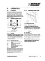
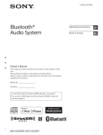
8.
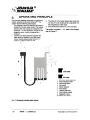
OPERATING PRINCIPLE
The machine operates according to a siphoning
system, patented by Bravilor Bonamat~. This
system has the following advantages:
1. The magnetic valve for dosing of the water is
located in the cold-water circuit. This largely
prevents the main cause for breakdowns in
machines - i.e. the formation of scale on the
magnetic valve - which is reduced to a
minimum.
2. Likewise, the electrodes that regulate the
water level are located in the cold-water
circuit, thereby reducing the formation of
scale to a minimum here as well.
11
3. The an
amount of hot water tapped per cycle does
not val
vary. It is not influenced by a standstill or by
the
the ten
temperature of the water.
4. The co
construction allows for a very compact
form.
form.
The
The posit!c
position numbers1.-10., used in this chapter,
refer to Fig
refer to Figure 17 .
12
~
9
8
7
.
.
Cold water
Hot water
1. Minimum level electrode
2. lime indicator level
3. Siphoningbasin
4. Hot water
5. Water selector
6. Flow boiler
7. Heating element
8. Cold-water supply
9. Magnetic valve
10. Measuring basin
Fig. 17 Operating principle water system
16
version
1.0 Bravllor Ltd.
CCopyright Bravilor Bonamat B. V.
I
BRAVILOR@
///hSONAMAT
8.1
The period the heating element is switched on
runs proportionally and will be at maximum
Afterconnectingand switchingon of the machine, (100"10)
(100%)value
value~f
if the
the temperature
temperature measured
measuredis
the operatingsystemwill first Initialiseitself.This
more
C below
more than
than 10
10°C
below the
the set temperature.
temperature.
~
Operation general
will takeapproximately
2 seconds.If necessary,
8.3.1
the water system will be filled with water.
Subsequently,the water will be heated to the
preset temperature. As soon as a beverage is
chosen by pressing a key, the water system is
activated first. Then the mixing system is activated,
Protection
The machine has the following protection levels:
1. Boiling protection
2. Overflow protection
3. Boiling dry protection
whereby
aningredient
is mixedwiththewater.
It ~ 4 4
8.3.1.1
IlE
- Depending on the beverage selected,
Ingredients from different ingredient
containers may flow out.
8.2
Operating system
The operating system, consisting of a print, both
control panels. and a number of electrodes,
operate the water system and the mixing system.
8.3
Water system
The water system, which consistsof a magnetic
valve (9.), a measuring basin (10.), a flow boiler
(6.) containing a heating element (7.), a siphoning
basin (3.) and a number of hoses. ensures a
correctdosing of hot water.
In the flow boiler (6.), a heating element (7.) Is
located. Two clicksons and an NTC resistor are
Installed on the flow boiler. This assembly
ensures that the water will remain at the preset
temperature.
If the flow boiler has been empty, for example
after installation or after a repair, the heating
element will remain switched on until the water
has reached a temperature of 10°C below the set
temperature. The residual heat of the heating
element will make sure that the temperature of
the water will rise some more. After a few
seconds, the heating element will alternatively be
switched on and off until the set temperature is
reached.
The temperature of the water is measured by an
temperature sensor, which is mounted on the
outside of the flow boiler. The NTC resistor,
together with the solid state relay, ensures correct
switchina- on and off of the heatina element.
Depending on the difference between the
temperature measured and the set temperature,
the thermostat will make sure that the heating
element Is switched on for a certain length of time.
cCopyright Bravilor Bonamat B.V.
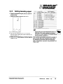
D_III_- -__&__&1_Boiling protection
The boiling protection, which consists of a
mechanical relay and the temperature sensor,
protects the machine from boiling.
The solid state relay is connected in series with a
mechanical relay. This mechanical relay is
switched on when the machine is switched on
and contains water, and off when the machine is
switchedoff. The solidstate relay is switched on
and off frequently to keep the water hot, while the
mechanical relay is switched on infrequently.
If the solid state relay breaks down, a direct
connection will be made, as a result of which the
heating element will be switched on constantly.
The temperature sensor constantly measures the
temperature of the water.
At the moment the water reaches a certain
temperature, the operating system will switch off
the mechanical relay, thereby switching off the
heating element as well. This prevents the water
from boiling.
In table 2 you can see when the mechanical
relay will be switched off.
Settemperat",.
of the water
90 °C
89OC
88 OC
Temperatureat which
the mechanicalrelay
will be switchedoff
97 °C
geoC
95 °C
~
emperare
relay
8.3.1.2
Overflow protection
If the magnetic valve should open up, whereas no
beverage selection key has been pressed, a timer
will start running for a maximum of 15 minutes. If
the magnetic valve should open up again within
this period. the machine will be blocked.
Bravilor
Ltd.
version
1.0
17
IIII BRAVILOR
(jj)
IIIIBONAMAT
8.5
Boiling
8.4
~
dry
The boiling dry protection is mounted on the
outside of the flow boiler using two clicksons.
These will switch off the heating element if it is
heated, by a malfunction, while there is no any
water in it.
ftI'
Dosing
The dosing of the hot water is achieved according
to the principle of communicating vessels. The
measuring basin (10.) forms a communicating
vessel with the siphoning basin (3.), via the hose
and the flow boiler (6.).
At the moment a beverage is selected, the
magnetic valve (9.) opens up. This causes the
measuring basin to be filled with tap water. At the
moment the water reaches the time indicator
level electrode (2.), the magnetic valve is closed
delayed. At that moment, the siphoning system in
the siphoning basin starts operating and the hot
water will be poured from the siphoning basin.
This pouring out of hot water will stop as soon as
the water level becomes lower than the siphon.
This way, a set amount of hot water is dosed.
The amount of water to be dosed may be
adjusted by leaving the magnetic valve open for a
certain, adjustable length of time after the water
has reached the time indicator electrode.
The expansion of the water, as a result of the
heating process, within the flow boiler does not
influence the amount of water dosed in any way.
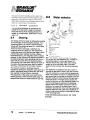
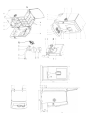
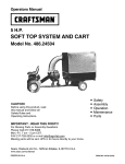
Water selector
,,1.
2.
3.
4.
5.
6.
7.
~
Fig.
The water selector, which consists of the base
(6.), an arm (2.), the distributor (4.), a motor with
positioning wheel (1.) and a light sensor (7.),
ensures that the hot water flows to the mixing
system or to the hot water outlet. The water
selector forms an entity with the siphoning basin
(3.).
The distributor is installed on the arm, which is
mounted on the base in such a way that it swivels.
The arm is driven by a motor with the positioning
wheel. The position of the arm is determined by the
light sensor that is mounted on the base.. The arm
features notches (5.) that interrupt the light beam
of the light sensor. The light sensor passes the
position of the arm on to the operating system. As
soon as a beverage is selected, the operating
system checks the position of the arm with the
distributor, by means of the light sensor, and if
necessary actuates the motor with the positioning
wheel to make sure the outlet of the distributor is
moved to the correct position underneath the outlet
of the siphoning basin.
There are three possible positions: left, middle
and right.
18
version
1.0 Bravilor Ltd.
@CopyrightBraviiorBonamatB.V.
'SRAVILOR@
- - - - - - - --
///h
8.6
Mixing system
The mixing system, consisting of the ingredient
container, the mixing units, and a number of
motors driving the ingredient containers and the
mixing units, ensures a correct dosing of the
ingredients and the mixing of the ingredients with
the hot water.
The moment the water reaches the time-indication
level electrode. the operating system will start
operating the motors of the ingredient containers
and the mixing units. Depending on the beverage
selected, one or more of the motors will be started
up. in consecutive order. The driving of the motor
for the ingredient container occurs by way of the
so-called 'Pulse Width Modulation'. This means
that the speed with which the motor is turning is
regulated in such a way that the powder flows into
the mixer at the exact same moment as the water.
This ensures the flowing of powder into the mixer
during the flowing of water, ensuring the emittance
of a smoothly mixed beverage.
8.6.1
Ingredient container
Inside the ingredientcontainerthereis a spiralto
transport the powder to the outlet. An antklogging
mechanism ensures that the powder inside the
ingredient container does not aet lumpy.
8.6.2 Mixing unit
The mixing unit consists of a mixing basin, the
mixing chamber, the mixer, the base plate, a hose,
the outlet piece, and a small exhaust fan, which
ensure the mixing of the hot water with the
Ingredient.
The moment the water reaches the time-indication
level electrode, the operating system will start
operating the motors of the Ingredient containers
and the mixing unit. At the same time, the hot
water is being siphoned. The powder from the
ingredient container reaches the mixing basin at
the same time as the hot water. This mix will flow
into the mixing chamber. Here. the mixture Is
mixed thoroughly and flows from the outlet piece.
Depending on the selectedbeverage,the operating
system will operate either of the two mixers.
(During the pouring of a halflwhole jug, the mixer
will tum during its first cycle or the whOOtprocess,
depending on the selected beverage. This prevents
a large head of foam from forming on top of the
beverage.)
The small exhaust fan removes the water vapour
that collects over each mixing chamber. This
prevents the ingredients in their containers from
getting damp. The water extraction is
accomplishedby two fans.
At the moment the water reaches the time
indicator level electrode, the operating system will
operate the anti-clogging mechanism.
CCopyright Bravilor Bonamat B.V.
Bravilor Ud.
version
1.0
19
IIII
~
,
'SRAVILOR@
- - - - - - - --
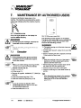
9.
MAINTENANCE BY SERVICE TECHNICIANS
9.1
Hygiene
Personal hygiene must be observed during all
cleaning and maintenance activities. Make sure
your hands are clean during these activities. Do
not smoke. Only use tools that are clean.
9.2.2
WAI1fJlIm
A Improper
. Inspectthe machinefor loosecomponents,
hosesand cables.
. Take the ingredient containers from the
.
maintenance
of the machine
cause health risks. Safeguard
may
the hygienic
condition of the machine while performing
maintenance activities on the machine.
9.2
Preventive
maintenance general
Before startingany maintenancedutieson the
machine, first contact the manager in charge of
the machine. The manager may be able to pass
on to you any complaints by the users (e.g. taste,
temperature or technical operation).
To be able to ensure a long life and correct
functioning of the machine. it will have to be
Inspected on a regular basis. Any defect
established during one of these inspections
should be remedied immediately.
9.2.1
.
.
Inspect whether the interior is clean.
Inspect the electronic operating unit on the
inside of the door.
machine and check the operation of the worm
(plastic) and spiral (metal).
. Inspect whether the ingredient containers are
.
clean.
Inspect the mixing units for leaks.
. Disconnect the mixing units (§5.2.3).
. Rinse all parts in wann water to which some
Cleaner is added.
. Lubricate the spindles of the mixers with a
silicone grease, suitable for foodstuffs.
. Mount the mixing units.
9.2.3
on the display. If so, descale the machine
accordingto the usermanual.
Inspect whether the machine is clean.
. Check the connections for the water supply
and the electricity supply.
9.3
. Inspectthe machinefor damages.
. Checkthe functioningof all selectionkeys.
. Inspectthe displayand makesure it Is legible.
Checkthe lockon the door.
Checkthe functioninaof the fans.
.
.
.
sure the fan has enouah room to rotate.
Inspect whether the fans are clean. Clean, If
V8fSion
Take the power off the machine by pulling the
plug from the socket.
. Remove the back plate from the machine after
unscrewingthe two plate screws.
. Clean the interior of the machine. using a
brush and vacuum cleaner.
. Inspectthe machinefor loosecomponents.
hosesand cables.
.
.
Inspect the interior for leaks.
Inspect the machine for damages.
. Put the back plate back on and fix it with the
two plate screws.
necessary
(§7.2).
20
Six-monthly
maintenance
. Inspect the ventilation grilles for dirt and make
.
Water system
. Check whether the descaling indicator appears
Outside
.
Interior
1.0 BravlIor Ltd.
CCopyrlght Bravilor Bonamat B. V.
III
'BRAVILOR@
- - - - - - - --
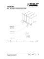
10.
10.1 Door and body
~
8.014.004.048
8.014.012.017
~
I
~I
~
I
~
I
$
CCopyright Bravllor Bonamat B.V.
I
~
I
~
I
~
Bravilor Ltd.
version
1.0
21
I
BRAVILOR
(jj)
~ BONAMAT
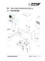
10.2 Electrical parts
8.QO8.OO1.1 01
22
version
1.0 BravllorLtd.
CCopyright Bravilor Bonamat B.V.
~
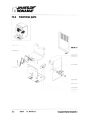
10.3
IBRAVILOR@
BONA MAT
Mixing system
* See §NO TAG
CCopyright Bravilor Bonamat B.V.
Bravilor Ltd.
version
1.0
23
BRAVILOR
IIIBONA MAT
,<8)
I
10.4
24
Water system
version 1.0 BravllorLtd.
CCopyright
Bravilor
Bonamat B.V.
(BRAVILOR@
h'll'hBONAMAT
10.5
Water selector
/~
,
rJ1I'
~
OCopyright Bravilor Bonamat B.V.
Bravilor Ltd.
version
1.0
25
BRAVILOR,@
BONA MAT
I
~
~
cO
i
.g
Q
~
c::)
~
i
1
~
Q)
iii
~
.!
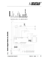
<mddw~ci~~~~~~zo~d~0
en
C
ten
-
~
«
a:
~
0
~
e"
d
(5
m
~
-c«
0
-
a::
tO
W
...J
W
m
~
C)
m
.-
'C
CJ
.-w
...
...
CJ
C1)
.
,...
,...
,...
26
version
1.0
Bravllor Ltd.
CCopyright Bravilor Bonamat B.V.
I BRAVILOR ,@
///1IBONA MAT
r
i
"I
~
"-
CD
as
~
Q
co
cO
j
Q
~
c::)
~
~
u"C
C»C»C»
i~
~~~
~~~ijjj
::=E~a..LLWWW
is
1
"i)
(1)
e
!
.1:0
~~ LL
cmddw~ci~~~~~2Z0~d~0
m
~
-~
a:
...J
><
..
0
~
-0
Q)
m
E
CO
~
C')
.'C
.-CJ
CO
~
....
CJ
- Q)
w
CCopyright Bravilor Bonamat B.V.
Bravilor Ltd. V8fSIon
1.0
27
BRAVILOR@
111'1
Ilj IBONAMAT
12.
REPAIR WORK
[£.)~rling
~
~
anyoftheactlvitias
below,
make sure that the voltage has been taken off
the machine, by pulling out the plug.
A Be careful of static electricity. Wear a wrist
band during the installation of the new
keyboard print.
WAl1NlIlG
A ~
starting
any of the activities below,
make sure that the machine has cooled down
sufficiently.
12.1
Operating
0
ing system
system
12.1.1 Exchanging the keyboard
print
of the user manual.
Water system
12.2.1 Draining of the water
A
&\
[
J~
system
DIalflowsout of the drainhose
maybeveryhot.
. Switch off the machine using the ON/OFF
.
Ill!
- See also the exploded view §10.4.
- See
The measuring basin is used to measure the
amount of water to be dosed.
switch.
Remove the drip-tray and open the door.
. Pullthe drain hose out of the machine for
some 5 ern.
. Place a receiving bin with a capacity of at least
7 litres under the drain hose.
II Parts of the interior of the machine may be
very hot. Allow the machine to cooldown
.
.
.
plate is fastened and remove the back plate.
Open the door and the flap.
Remove the plug from the pouring opening.
Disconnect both hoses that connect to the
measuring basin.
. Unscrew the screw with which the measuring
basin is fastened (next to the pouring opening
for descaler) and take the measuring basin
from the machine.
. Disconnect the wiring.
The measuring basin is now completely
disassembled and the new measuring basin may
now, in reverse order, be installed.
IlE
- The connection pins of the measuring basin
are coded.
. Connect the red wire to the H. Connect the
black wire to the L. Connect the green!yellow
wire to the earth connection.
the water flow into the receiving bin.
. Place the plug back on the drain hose.
version
1.0 Bntvllor Ltd.
[
sufficiently.
. Take the power off the machine by pulling the
plug from the socket.
. Take the pressure off the water system by
turning the tap off at the water connection point.
. Drain the water system (§ 12.2.1).
. Remove the plug from the drain hose and let
28
(
WAllNlIm
. Unscrew the two screws with which the back
Programme the keyboard print according to
the instructions given in the table on the insert
12.2
12.2.2 Exchangingthe
measuring basin
CCopyright Bravilor Bonamat B. V.
,
IIII BRAVILOR@
IIIIBONAMAT
~
ing the
the NTC
NTC
Exchanging the flow boiler 12.2.4 Exchanging
resistor
IJE
- Seealsothe explodedview§10.4.
12.2.3
DE
J
The flow boilerservesas a reservoirfor hotwater. - See also the exploded view §10.4.
It containsthe heatingelementthat heatsthe
The NTC resistor (temperature sensor) constant
water.
monitors the temperature of the flow boiler.
[
A
~
]~
interior of the mechine may be
WAl1fJlN1l
~
!::!.Parts of the interior of the machine may be ~
very hot. Allow the machine to cool down
sufficiently.
sufficiently.
. Take the power off the machine by pulling the
. Take the power off the machine by pulling the
plug from the socket.
plug from the socket.
. Take the pressure off the water system by
. Remove the back plate from the machine after
tuming the tap off at the water connection point.
unscrewing the two plate screws.
. Drain the water system (§12.2.1).
. Disconnect both plugs that connect the wiring
. Unscrew the two screws with which the back
of the NTC resistor to the operating point.
plate is fastened and remove the back plate.
. Unscrew the nut of the NTC resistor and
Disconnect the NTC resistor.
remove the NTC resistor.
. Disconnect the earth wiring.
The NTC resistor Is completely disassembled now,
. Disconnect the wires to both of the clicksons.
and may be replaced. The new NTC resistor has to
be installed in the exact reversed order.
. Disconnect both hoses.
. Push the lip in the base plate down (at the
12.2.5 Siphoning
Siphoning basin
basin I water
water
backmost support block) and slide the flow
selector
boiler, together with the backmost support
block, in the direction of the door, until the
support block is released from the base plate.
12.2.5.1 Exchanging the siphoning
basin I water selector
. Take out the flow boiler, together with the
support block, from the machine.
The siphoning basin provides the water selector
Disconnect both wires to the heating element.
with hot water.
The flow boiler is completely disassembled now,
The water selector provides the brewer with hot
and may be replaced. The new element has to be water, or lets the hot water flow out of the hot
installed in the exact reversed order.
water outlet.
Possible defects:
1. The light sensor is defective.
2. The connecting wire connecting the light
sensor is loose or defective.
3. The water-selector drive has broken down.
very hot. Allowthe machineto cool down
.
.
~
~
t1 Parts of the interior of the machine may be [
very hot. Allow the machine to cool down
.
sufficiently.
. Take the power off the machine by pulling the
plug from the socket.
. Take the pressure off the water system by
turning the tap off at the water connection point.
Drain the water system (§12.2.1).
Remove the back plate from the machine after
.
.
unscrewingthe two platescrews.
CCopyright Bravilor Bonamat B. V.
Bravilor Ltd.
version
1.0
29
I
BRAVILOR@
Illj'hBONAMAT
.
Remove the drip-tray.
Open the door and the flap.
. Take the ingredient container from the machine.
. Disconnectthe hose to the flow boiler.
.
.
rn
,
Disconnect the three hoses that are connected
to the water selector.
. Unscrew the siphoning basin / water selector
by unscrewing the three screws.
~-
lightsensoris alsodisconnected.
Theyare
fixed simultaneously, with the screw at the
bottom.
. Take the water selector from the machine and
remove the hosing.
The water selector is completely disassembled
now, and may be descaled or replaced. The new
water selector has to be Installed in the exact
reversed order.
12.2.5.2 Descaling of the water
selector
[Jt]
,
WARNING
f::J.Always wear
gloves and protective facial gear
duringthe descalingprocedure.
. Disconnectthe waterselector(§12.2.5.1).
. Dissolve 100 9 Renegite in half a litre of hot
.
selector motor
DE
- See also the exploded view §10.4.
-See
The water selector motor positions the arm of the (
water selector.
WAl1NlI!m
A Parts of the interior of the machine may be
Once the water selector is disconnected,the
.
.
12.2.6 Exchanging the water
water.
Pour the descaling solution into a bucket.
veryhot.Allowthe machineto cooldown
sufficiently.
. Take the power off the machine by pulling the
. Take the water selector from the descaling
solution.
. Thoroughlyrinsethe waterselectorwith clean
water.
.
plug from the socket.
tuming the tap off at the water connection point.
Drain the water system (§12.2.1).
. Unscrew the two screws with which the back
plate Is fastened and remove the back plate.
Remove the drijrtray.
. Open the door and the flap.
. Take the ingredient container from the machine.
. Disconnectthe hose to the flow boiler.
. Disconnectthe three hoses that are connected
to the water selector.
Unscrew the siphoning basin I water selector
by unscrewing the three screws.
. Unscrew the motor by unscrewing the two
screws at the front, with which it is fastened.
Disconnectthe wiring.
.
.
.
.
CAlJIKHJl
CAlJIK»Jl
..
-
The wiring to the drive motor has to be
properly connected:
the red wire to the + (plus) connection and
the black wire to the - (minus) connection.
Dry the water selector.
. Reassemble the water selector.
The water selector may now be reinstalled into
the machine. The water selector has to be installed
in the exact reversed order of disassembly.
30
V8fSion 1.0 BfavlIorltd.
,
. Take the pressure off the water system by
. Placethe waterselectorin the bucketwith
The motor is completely disassembled now, and
descalingsolutionand makesureit Is
may be replaced. The new motor has to be
completelyimmersed.
installed in the exact reversed order.
. Leave the water selector to soak in the descaling
solution for aDDroximatelv 15 minutes.
~
[
OCopyright Bravilor Bonamat B. V.
rn
[
fSRAVILOR@
S ONA MAT
Illh
12.2.7 Exchangingthe light
sensor
12.2.8 Exchangingthe
connecting wire to the
light sensor
~~ee
~
alsotheexploded
view§10.5.
The light sensor checks the position of the water
selector. When the water selector is in the correct
position, the light sensor will pass on a signal to
the operating print, so that the selected process
may be performed.
The light sensor is connected to the operating
print with a connecting wire.
WARNING
WAl1Nll«1
very hot.Allowthe machineto cooldown
.
[ ~
~
]~
Interior of the mechlno may be
very hot. Allow the machine to cool down
sufficiently.
. Take the power off the machine by pulling the
plug fromthe socket.
. Take the pressure off the water system by
.
turning the tap off at the water connection point.
Drain the water system (§12.2.1).
. Unscrew the two screws with which the back
.
plate is fastened and remove the back plate.
.
.
.
.
.
.
.
Remove the drip-tray.
. Open the door and the flap.
.
Take the ingredient container from the machine.
.
.
.
Unscrew the water selector by unscrewing the
three screws.
11lt the water selector to the back slightly. This
allows the light sensor to be taken out, because
it has become disconnected by unscrewing the
screw at the bottom.
. Disconnect the light sensor and take the light
sensor from the machine.
The light sensor is completely disassembled now,
and may be replaced. The new light sensor has
to be installed in the exact reversed order.
l
t:J.Parts of the interior of the machine may be
.
.
.
.
sufficiently.
Take the power off the machine by pulling the
plug from the socket.
Take the pressure off the water system by
turning the tap off at the water connection point.
Drain the water system (§12.2.1).
Unscrew the two screws with which the back
plate is fastened and remove the back plate.
Remove the drij:Hray.
Open the door and the flap.
Take the ingredient container from the machine.
Unscrew the water selector by unscrewingthe
three screws.
Tilt the water selector to the back slightly. This
allows the light sensor to be taken out, because
it has become disconnected by unscrewingthe
screw at the bottom.
Disconnectthe light sensor and take the
connecting wire from the machine.
At the other end, disconnect the connecting
wire from the print.
Take the connecting wire from the cable clamp.
The connecting wire is completely disassembled
now, and may be replaced. The new connecting
wire has to be installed in the exact reversed order.
The light sensor contains a notch that should
drop in a hole in the plate.The light sensor
contains a notch that should drop in a hole in
the plate.
plate.
CCopyright Bravilor Bonamat B.V.
Bravllor Ltd.
version
1.0
31
BRAVILOR@
BONAMAT
r
12.3 Mixing system
12.3.1 Exchanging the ingredient 12.3.1.2Exchangingmotor2 or 3
container motors
WARNING
IJE
-
!:t. Parts of the interior of the machine may be
See also the exploded view § 10.3.
The ingredient container motor drives the worm
or spiral and the antl-caking mechanism within
the ingredient container.
very hot. Allow the machine to cool down
sufficiently.
Take the power off the machine by pulling the
plug from the socket.
Take the pressure off the water system by
tuming the tap off at the water connection point.
.
.
.
~
l.
Drain the water system (§12.2.1).
. Unscrew the two screws with which the back
12.3.1.1 Exchanging motor 1
[
A
~
]~
ioteri<><
of the machinemaybe
veryhot.Allowthemachine
to cooldown
sufficiently.
. Take the power off the machine by pulling the
.
.
plug from the socket.
Take the pressure off the water system by
turning the tap off at the water connectionpoint.
Drain the water system (§12.2.1).
. Unscrew the two screws with which the back
plate Is fastened and remove the back plate.
. Open the door and the flap.
.
.
Take the ingredient container from the machine.
Remove the plug from the pouring opening.
. Unscrew the screw with which the measuring
basin is fastened.
. Tilt the measuring basin to the back slightly.
. Disconnect both wires to the motor.
. Unscrew both mounting screws, with which the
motor is mounted.
Take the motor from the machine.
plate is fastened and remove the back plate.
.
.
Open the door and the flap.
Take the ingredient container from the machine.
. Unscrew the siphoning basin I water selector
by unscrewing the three screws.
. Tilt the siphoning basin I water selector to the
back slightly.
Disconnect both wires to the motor.
.
.
Unscrew both mounting screws, with which the
motor is mounted.
. Take the motor from the machine.
The motor (ingredient container 2 or 3) is now
completely disassembled and the new motor
may now, in reverse order, be installed.
-
CAJJIKJNl
-
The wiring to the drive motor has to be
properly connected:
the red wire to the + (plus) connection and
the black wire to the - (minus) connection.
.
[I],
The motor (ingredient container 1) is now
completely disassembled and the new motor
may now, In reverse order, be installed.
CAlJIK2W.
- The wiring to the drive
.
motor has to be
property
connected:
the red wire to the + (plus) connection and
the black wire to the - (minus) connection.
32
version
1.0 Bravllor Ltd.
CCopyright Bravilor Bonamat B. V.
rn
[
I BRAVILOR
///hBONA
12.3.1.3 Exchanging motor 4
£\A.
[
]~
interior of the machine may be
sufficiently.
. Take the power off the machine by pulling the
plug from the socket.
Take the pressure off the water system by
turning the tap off at the water connectionpoint.
. Unscrew the two screws with which the back
.
MAT
12.3.2 Exchangingthe mixing
unit motor
veryhot.Allowthemachine
to cooldown
.
'@
plate is fastened and remove the back plate.
ne
IJE!
- See also the exploded view §10.3.
~
- Seealso the exploded view §10.3.
The mixing unit motor drives the mixer.
Take the power off the machine by pulling the
plug from the socket.
.
. Unscrew the two screws with which the back
.
plate Is fastened and remove the back plate.
Open the door and the flap.
. Disconnectthe mixing unit (§5.2.3).
. Disconnect both wires to the motor.
. Unscrew both mounting screws, with which the
motor is mounted.
Open the door and the flap.
. Take the ingredient container from the machine.
. Disconnect both wires to the motor.
. Unscrew both mounting screws, with which the
Take the motor from the machine.
motor Is mounted.
The mixing unit motor is now completely
Take the motor from the machine.
.
.
The motor (ingredient container 4) is now
completely disassembled and the new motor
may now, in reverse order, be installed.
rn
,
~-
.
The wiringto the drivemotorhasto be
property
connected:
disassembled and the new motor may now, in
reverse order, be installed.
CAUTION!
OJ
The wiring to the drive motor has to be
properly connected:
the red wire to the + (plus) connection and
the black wire to the - (minus) connection.
the red wireto the + (plus) connection and
the black wire to the - (minus) connection.
CCopyright Bravilor Bonamat B.V.
Bravilor ltd.
version
1.0
33
//1
~
'SRAVILOR@
12.4 Miscellaneous components
. Take the mounting plate from the machine, so
12.4.1 Exchanging the
trans
f
ne
- See also the explodedview §10.2.
10the exploded view §10.2.
,"""or rMII
In.. unl+an.a.
The transformer
reducestho
the mains
voltage tnto ?A
24
Volts.
A
~
[
]~
CAJJIK»Jl
-
properly connected:
the red wire to the + (plus) connection and
the black wire to the - (minus) connection.
veryhot.Allowthemachine
to cooldown
plug from the socket.
. Unscrew the two screws with which the back
plate is fastened and remove the back plate.
.
.
Note down the connections of the wiring.
Disconnect the plugs.
. Unscrew the screw with which the mounting
plate is fastened.
.
Take the mounting plate from the machine, so
that the mounting nuts can be loosened from
the transformer.
The transformeris now completely disassembled
and the new transformer may now, in reverse
order, be installed.
12.4.2 Exchangingthe solid
state relay
IlE
- See also the exploded
view §10.2.
The solid state relay switches the heating element
on and off.
A
~
The solid state relay is now disassembled and the
new solid state relay (inel. conductive plate) may
now, in reverse order, be installed.
interiorof the machinemaybe
sufficiently.
[
fromthe solidstaterelay(incl.conductiveplate).
- The wiring to the solid state relay has to be
. Take the power off the machine by pulling the
~
that the mounting screws can be unscrewed
ormer
]~
interiorof the machinemaybe
veryhot.Allowthemachine
to cooldown
sufficiently.
. Takethe poweroff the machineby pullingthe
Dluafromthe socket.
12.4.3
12.4.3 Exchanging the exhaust
fan motor
DE
-
See also the exploded view §10.2.
The exhaust fans removes the water vapour that
collects over the mixing unit.
. Take the power off the machine by pulling the
plug from the socket.
. Unscrew the two screws with which the back
plate is fastened and remove the back plate.
. Unscrew the two screws with which the side
planel is fastened (at the bottom) and remove
the back plate.
Unscrew the blower housing screws.
. Disconnectthe wiring of the ventilator from the
operating print.
. Take the blower housing from the machine.
. Unscrew the two screws with which blower
motor is fastened.
.
A new fan may now be mounted. The new fan
must be installed in the exact reversed order.
CA1JIK}}Jl
.. .
The wiring to the drive motor has to be
properly connected:
the red wire to the + (plus) connection and
the black wire to the - (minus) connection.
. Unscrew the two screws with which the back
plate is fastened and remove the back plate.
.
Note down the connections of the wiring.
. Disconnectthe Dluas.
.
Unscrew, the screw with which the mounting
plate is fastened.
34
Yef8ion
1.0 Bravllor Lid.
[I]
CCopyright Bravilor Bonamat B. V.
ITJ
IIIIBRAVILOR@
III1 BONA MAT
13.
CORRECTING MALFUNCTIONS
In case of malfunctions first consult the malfunctions tables. If the problem cannot be solved, consult
your Bravilor Bonamat dealer.
13.1
CCopyright
Malfunctioning analysis general
Bravilor
Bonamat B.V.
Bravilor Ltd.
version
1.0
35
IIII BRAVILOR@
IIIIBONAMAT
13.2
36
Display messages and their meanings
V8fSion
1.0 Bravilor Ltd.
CCopyright Brayllor Bonamat B. V.
Enclosures
////BRAVILOR@
////BONAMAT
14.
CCopyright Bravilor Bonamat B.V.
Bravilor Ltd. version
1.0
37
(BRAVILOR @
//1 BONAMAT
38
version
1.0 Bravilor ltd.
Enclosures
CCopyright Bravilor Bonamat B.V.
/BRAVILOR@
///1
- - --SONAMAT
--~
---Enclosures
S
AS
. ,
.-
= Spare parts
= Recommendedspare parts
CCopyright
Bravllor
Bonamat B. V.
Bravilor ltd.
version
1.0
39
(BRAVILOR@
MAT
//1BONA
15.
Enclosures
SPECIAL CODES
15.1 Resetting the daycounters to zero
.
.
Select any drink with one of the selection buttons.
Keep the button pressed down during 5 seconds.
The counter for 811drinks is reset to zero for cups, mugs, half jugs and whole jugs.
15.2
Resetting the total counters to zero
. Press the programming button (18.2) to startthe programming.
Press any key and keep the button pressed down during 5 seconds.
.
The total counter for all drinks is reset to zero for cups, mugs, half jugs and whole jugs.
15.3 Interrupt the descaling programm
- If the descallnghasstartedin the meantime,thenpushlonger than 10 seconds on the setting
key (4.13)to stopthe descalingprogramme.
[Ji\.)~escaling
40
programme
neverwhenyouhovealreedypoureddescaJer
Intothemeehlnel
version
1.0 Bravilor Ltd.
CCopyrlght Bravilor Bonamat B.V.
"
I ' BRAVILOR@
"j 'BONAMAT
Enclosures
16.
CONSUMABLE ITEMS AND ACCESSORIES
16.1 Recommendedconsumable items
16.2 Accessories
16.2.1 Raising feet
Set of extra feet to raise the apparatus 2 em so
that larger cups or cans can be placed under the
drink outflow. Now the drip tray is standing loose
in front of the machine.
Fig. 19 Raising foot
Ordering number. 7.270.201.101 (set of 4 pieces)
CCopyright Bravilor Bonamat B.V.
Bravilor Ltd.
version
1.0
41
IIII
17.1 Assembly of the water selector bracket
~
(1x)
1)
c
B (1x)
2b)
2a)
~
3)
4)
(3x)
~
,
.
c
5)
!
42
version
1.0 BravlIor Ltd.
CCopyrIghx Bravilor Bonamat B.V.
/ / / / BRAVILOR
/ / / / BONA MAT
Enclosures
~"'
l'
17.2
(jj)
-.
,
Condens reservoir and outlet
~
6.030.072.011
6.030'072,OI°'Y
.
Please note:
- If you order the 6.030.071.006
instead of the 6.030.007.001,
you have to replace the outletsas
well.
CCopyright Bravilor Bonamat B.V.
Bravilor Ltd.
version
1.0
43
cCopyright
Bravilor
Bonamat B. V.
700.403.311
u
GO
~
e~