1
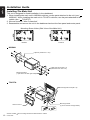
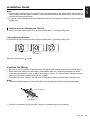
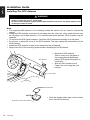
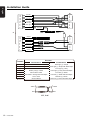
Installation Guide
English
Before Starting
Car battery
1.This set is exclusively for use in cars with a
negative ground, 12 V power supply.
2. Read these instructions carefully.
3.Be sure to disconnect the battery “ ” terminal
before starting. This is to prevent short circuits
during installation.
Package Contents
Source unit.................................................1
Wire connector...........................................1
GPS antenna..............................................1
CLAMP for GPS antenna’s cable...............3
DOUBLE FACE TAPE for GPS Antenna...1
Cleaning cloth.............................................1
Warranty Card............................................1
Quick Start Guide.......................................1
Owner’s manual (CD-R).............................1
Electro tap..................................................2
Flush mount bolts(M5x6)............................8
Hexagon Head Screw(M5x6).....................8
Rear Stud Bolt............................................1
Rubber Parts..............................................1
AV cable.....................................................1
Cautions On Installation
1.Prepare all articles necessary for installing
the main unit before starting.
Max. 30°
2.Install the unit within 30° of the horizontal
plane.
Chassis
3.If you have to do any modification on the
car body, such as drilling holes, consult
your car dealer beforehand.
Damage
4.Use the included screws for installation.
Using other screws can cause damage.
Max. 6 mm (M5 screw)
NX302E
11
Installation Guide
English
Installing The Main Unit
This unit is designed for fixed installation in the dashboard.
1.When installing the main unit in NISSAN vehicles, use the parts attached to the unit (see “
NISSAN”). When installing the main unit in TOYOTA vehicles, use the parts attached to the
vehicle (see “ TOYOTA”).
2.Wire as shown in “Wire Connection”.
3.Reassemble and secure the unit in the dashboard and set the face panel and center panel.
Mounting Screw Holes (Side View of the Main Unit)
NISSAN
TOYOTA
NISSAN
6-Spacer (thickness: 1 mm)
6-Flat head screw (M5 × 6)
(attached to the main unit)
Mounting bracket
(1 pair for the left and right sides)
TOYOTA
8-Hexagonal screw (M5 × 6)
Mounting bracket
(1 pair for the left and right sides)
Center Panel *1
*2
Screws marked
12
NX302E
and mounting bracket are attached to the vehicle.
Installation Guide
*1Some panel openings are too small for the unit depending on the vehicle type and model. In
such a case, trim the upper and lower sides of the panel frame by about 0.5 to 1.5 mm so the
unit can be inserted smoothly.
*2If a hook on the installation bracket interferes with the unit, bend and flatten it with a nipper or
similar tool.
English
Note:
Vehicles other than NISSAN and TOYOTA
In some cases the center panel may require modification. (Trimming, filling, etc.)
Typical Mounting Brackets
In some cases the center panel may require modification. (Trimming, filling, etc.)
Example 1-3
Affix the screws to the
marks.
Cautions On Wiring
•Be sure to turn the power off before wiring. Be particularly careful where you route the wires.
•Keep them well away from the engine, and exhaust pipe, etc. Heat may damage the wires.
•If the fuse should blow, check to see if the wiring is correct. If a fuse is blown, replace it with a
new one of the same specification as the original.
• To replace the fuse, remove the old fuse of the power supply cord and insert the new one.
Note:
• There are various types of fuse holder. Do not let the battery side touch other metal parts.
Fuse (15A FUSE)
Fuse holder
• After the connection, fix the cord by a clamp or insulation tape for protection.
NX302E
13
Installation Guide
English
Installing The GPS Antenna
WARNING
•Do not install the GPS antenna in a place where it may interfere with the operation of the
airbag or hinder the driver’s visual range.
•Do not use the navigation system with the GPS antenna cord cut off. The power cables in the
cord may be short-circuited.
Note:
• T
he supplied GPS antenna is for installing inside the vehicle. Do not install it outside the
vehicle.
• Install the GPS antenna more than 50 cm away from the main unit, other audio devices such
as CD player, and a radar detector. If it is installed near these devices, GPS reception may be
impaired.
• To improve the GPS signal reception, install the GPS antenna horizontally on a flat plane.
• Do not wax or paint the cover of the GPS antenna. This may reduce the performance of the
GPS antenna.
• Install the GPS antenna at least 10 cm away from the windshield.
• Wipe off the dirt of the mounting surface before installing the GPS antenna.
GPS antenna
• Mount the GPS antenna.
Stick it surely on a flat plane of
the passengerside dashboard
where GPS signal interruption is
minimized.
• Wire the GPS antenna cord.
Fasten the cord using the cord
holders.
Cord holder
Double-sided tape
•Stick the double-sided tape to the bottom
face of the GPS antenna.
Bottom face of the GPS antenna
14
NX302E
NX302E
Installation Guide
English
Wire Connection
GPS
GPS Antenna
Antenna
(Black)
(Black)
(Black)
(Black)
Radio
RadioAntenna
Antenna
C
B
1
2
3
4
5
6
7
8
Referto
to next
next page.
Refer
page.
Black
Black
Black
Black
Black
Black
A
1
2
3
4
5
6
7
8
ExternalMicrophone
MicrophoneConnection
Connection
External
White
White
Red
Red
Black
Black
VISUAL
VISUAL IN
IN
Line
Line Out
OutRear
RearLeft
Left
Subwoofer
Subwoofer11
Line Out
OutRear
RearRight
Right
Line
Subwoofer22
Subwoofer
2-Channel Amplifier
Amplifier
2-Channel
Video
Video Out
Out
Yellow
Yellow
®
iPod/iPhone
iPod/iPhone
CCA-750
CCA-750
(sold separately)
separately)
(sold
Black
Black
CAMERA
CAMERA
Gray
Gray
Yellow
Yellow
Video
VideoOut
Out
Rear
Camera
RearVision
Vision Camera
Gray
Gray
Steering
Terminal
SteeringWheel
WheelRemote
RemoteControl
Control
Terminal
Black
Black
USB
USB connector
connector
or
or
USB Memory
Memory
USB
NX302E
15
Installation Guide
English
B
18
16
14
12
10
8
6
4
2
Rear left -
1
3
5
7
Rear left +
Front left Front left +
Front right +
2
4
6
8
Front right Rear right +
Rear right Fuse 15A
Battery +
C
A
17
15
13
11
9
7
5
3
1
Location
Reverse
1
3
5
7
Parking
ACC +
AUTO ANT
AMP Remote
2
4
6
8
Illumination
Phone Mute
Groundd
Function
Connector A
Connector B
Rear right (+) / Purple
Rear right (-) / Purple with black stripe
Front right (+) / Gray
Battery 12V(+) / Yellow
Auto Antenna / Blue
Front left (+) / White
Illumination / Orange with white stripe
Front left (-) / White with black stripe
ACC+ / Red
Rear left (+) / Green
Ground / Black
Rear left (-) / Green with black stripe
Yellow
Yellow
Red
Red
VW, Audi
16
NX302E
Front right (-) / Gray with black stripe
Installation Guide
*1Connect to the AUX audio input terminal and the iPod video input terminal. (Audio connection
is required only when [Analog] is selected for the iPod output signal. See Owner’s Manual.)
*2In certain vehicles - Volkswagen/Opel/Vauxhall - it is necessary to exchange the accessory
<<Red>> and the main power <<Yellow>> connection, to avoid overload and loss of memory.
*3When the unit is installed in a 1998 or later Volkswagen model, make sure to interrupt the
<<Remote>> output.
Disconnect the <<blue/white>> wire and insulate the front ends of this cord. A breakdown may
occur if the cord is not disconnected, or front ends are not insulated.
English
Note:
Connecting the parking brake cord
Connect the cord to parking brake lamp ground in the meter panel.
Note:
• C
onnecting the parking brake cord to lamp ground allows you to watch video images when
the parking brake is engaged.
• When the parking brake cord is not connected, the monitor will not display video images.
Parking brake lamp
cord to battery
Parking brake
Electro-tap
Parking brake signal cord
Parking brake cord (Grass-green)
Parking brake signal cord
Stopper
Parking brake cord (Grass-green)
NX302E
17