1
Thermo Scientific Dionex
Charged Aerosol Detectors
Corona Veo and Corona Veo RS
Operating Instructions
(Original Operating Instructions)
Revision: 1.0
Date: July 2013
© 2013 Thermo Fisher Scientific Inc.
Doc. No. 4820.8101
Charged Aerosol Detectors
Corona Veo and Corona Veo RS
Operating Instructions
Charged Aerosol Detectors
Corona Veo and Corona Veo RS
Declaration of Conformity
(Original Declaration of Conformity)
Product:
Thermo Scientific Dionex - Detector
Types:
Corona Veo and Corona Veo RS
Dionex Softron GmbH herewith declares conformity of the above products with
the respective requirements of the following regulations:
• Low-Voltage Directive 2006/95/EC
• EMC Directive 2004/108/EC
The electrical safety of the products was evaluated based on the following
standard:
• DIN EN 61010-1:2010
Safety requirements for electrical equipment for measurement, control and
laboratory use, Part 1: General Requirements
The Electromagnetic Compatibility (EMC) of the products was evaluated based
on the following standard:
• DIN EN 61326:2006
Electrical equipment for measurement, control and laboratory use
EMC Requirements
Responsible for the technical CE documentation is the manufacturer (see further
down).
This declaration is issued for the manufacturer
Dionex Softron GmbH
Part of Thermo Fisher Scientific Inc.
Dornierstraße 4
D-82110 Germering
by Managing Director, Rüdiger Obst, and
Vice President HPLC, Fraser McLeod.
June 17, 2013
Operating Instructions
Page I
Charged Aerosol Detectors
Corona Veo and Corona Veo RS
Page II
Operating Instructions
Charged Aerosol Detectors
Corona Veo and Corona Veo RS
Table of Contents
1
Introduction................................................................................................................... 1
1.1 How to Use This Manual ........................................................................................... 1
1.2 Safety ......................................................................................................................... 3
1.2.1 Symbols on the Detector and in the Manual ...................................................... 3
1.2.2 Safety Precautions.............................................................................................. 4
1.2.3 Consignes de Sécurité ........................................................................................ 7
1.3 Intended Use ............................................................................................................ 11
1.4 Federal Communications Commission (FCC) Note ................................................ 13
2
Overview ...................................................................................................................... 15
2.1
2.2
2.3
2.4
2.5
2.6
2.7
2.8
2.9
2.10
2.11
2.12
3
Unit Description ....................................................................................................... 15
Detector Configurations ........................................................................................... 16
Operating Principle .................................................................................................. 17
Interior Front Panel .................................................................................................. 19
Rear Panel ................................................................................................................ 20
Flow Connections .................................................................................................... 21
Nebulizer .................................................................................................................. 21
Manual Gas Regulator Knob (Corona Veo only) .................................................... 21
Stream-Switching Valve (Corona Veo RS only) ..................................................... 21
Leak Sensor.......................................................................................................... 22
Detector Display .................................................................................................. 22
Self-Test Diagnostics and Preventive Maintenance ............................................ 22
Installation ................................................................................................................... 23
3.1 Facility Requirements .............................................................................................. 23
3.2 Unpacking the Detector ........................................................................................... 26
3.3 Positioning the Detector in an UltiMate 3000 System ............................................ 27
3.4 Connecting the Detector Rear Panel ........................................................................ 29
3.4.1 Overview of Connections ................................................................................ 29
3.4.2 Connecting the Power Cord ............................................................................. 29
3.4.3 Connecting the USB Cable .............................................................................. 30
3.4.4 Connecting the Digital I/O ............................................................................... 31
3.4.5 Connecting the Analog Signal Output ............................................................. 32
4
Preparation for Operation (Startup) ........................................................................ 33
4.1 Overview of Actions ................................................................................................ 33
4.2 Connecting the Drainage ......................................................................................... 34
4.3 Connecting the Gas Supply and Exhaust Tubing .................................................... 35
4.4 Making Flow Connections ....................................................................................... 36
4.4.1 General Guidelines .......................................................................................... 36
4.4.2 Capillary Connections in an UltiMate 3000 System ....................................... 37
4.4.3 Installing the In-Line Filter (optional) ............................................................. 38
4.4.4 Connecting Capillaries to the Detector ............................................................ 39
Operating Instructions
Page i
Charged Aerosol Detectors
Corona Veo and Corona Veo RS
4.4.5 Connecting the Stream-Switching Valve (Corona Veo RS only) .................... 40
4.5 General Guidelines for Detector Operation ............................................................. 41
4.5.1 Mobile Phase .................................................................................................... 41
4.5.2 Mobile Phase Delivery System ........................................................................ 42
4.5.3 Gas Supply ....................................................................................................... 42
4.5.4 Ventilation........................................................................................................ 43
5
Operation ..................................................................................................................... 45
5.1 Safety Guidelines for Operation .............................................................................. 45
5.2 Turning on the Power to the Detector ...................................................................... 47
5.3 Operating the Detector from the Touch Screen ....................................................... 48
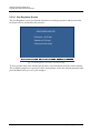
5.3.1 Overview .......................................................................................................... 48
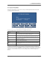
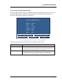
5.3.2 Main Menu ....................................................................................................... 49
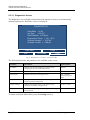
5.3.3 Run Mode Menu .............................................................................................. 50
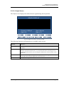
5.3.4 System Setup Menu ......................................................................................... 55
5.4 Before Operating the Detector ................................................................................. 59
5.4.1 Setting the Gas Pressure ................................................................................... 59
5.4.2 Preparing the System ....................................................................................... 61
5.4.3 Equilibrating the Detector ................................................................................ 62
5.5 Performing Sample Analysis ................................................................................... 64
5.5.1 Starting and Stopping Data Acquisition........................................................... 64
5.5.2 Operating the Stream-Switching Valve (Corona Veo RS only) ...................... 64
5.6 Optimizing the Detector Performance ..................................................................... 65
5.6.1 General Guidelines ........................................................................................... 65
5.6.2 Setting a Filter Constant ................................................................................... 66
5.6.3 Selecting the Evaporation Temperature ........................................................... 66
5.6.4 Using Gas Flow Modes (Corona Veo RS only) ............................................... 67
5.6.5 Applying a Power Function Value ................................................................... 68
5.6.6 Minimizing Baseline Noise.............................................................................. 68
5.6.7 Digital Data Collection Rate Guidelines .......................................................... 69
5.7 Internal Safety Features ........................................................................................... 70
5.7.1 Leak Detection ................................................................................................. 70
5.7.2 Internal Liquid Detection ................................................................................. 70
5.7.3 Gas Supply Pressure Relief Valve ................................................................... 71
5.7.4 Flow Ratio Alarm............................................................................................. 72
5.7.5 Detector Flooding Alarm ................................................................................. 72
5.8 Shutting Down the Detector..................................................................................... 74
5.8.1 Short-term Shutdown ....................................................................................... 74
5.8.2 Long-term Shutdown ....................................................................................... 74
6
Chromeleon Software ................................................................................................. 77
6.1 Setting Up the Detector in Chromeleon ................................................................... 78
6.1.1 Loading the USB Driver for the Detector ........................................................ 78
6.1.2 Installing the Detector ...................................................................................... 80
6.1.3 Configuring the Detector ................................................................................. 81
6.2 Setting Up the Detector in DCMSLink .................................................................... 84
Page ii
Operating Instructions
Charged Aerosol Detectors
Corona Veo and Corona Veo RS
6.3 Operating the Detector from Chromeleon ............................................................... 85
6.3.1 Connecting to Chromeleon .............................................................................. 85
6.3.2 Direct Control .................................................................................................. 86
6.3.3 Automated Control .......................................................................................... 88
7
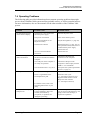
Troubleshooting .......................................................................................................... 91
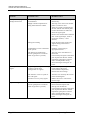
7.1
7.2
7.3
7.4
8
Overview .................................................................................................................. 91
Self-Test Error Codes .............................................................................................. 93
Warning and Error Codes ........................................................................................ 95
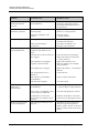
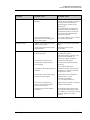
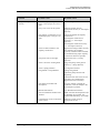
Operating Problems ................................................................................................. 99
Maintenance .............................................................................................................. 107
8.1 Safety Guidelines for Maintenance........................................................................ 107
8.2 Returning the Detector for Repair ......................................................................... 108
8.3 Routine and Preventive Maintenance .................................................................... 109
8.3.1 Inspection and Service Plan ........................................................................... 109
8.3.2 Maintaining the Detector between Analyses ................................................. 111
8.3.3 Cleaning the Surface of the Detector ............................................................. 111
8.3.4 Operational Qualification and Performance Qualification ............................ 111
8.4 Eliminating Leakage .............................................................................................. 112
8.5 Replacing the Gas Filters ....................................................................................... 113
8.6 Removing the Nebulizer ........................................................................................ 115
8.7 Stream-Switching Valve (Corona Veo RS only) ................................................... 116
8.7.1 Disassembling the Valve ............................................................................... 116
8.7.2 Assembling the Valve .................................................................................... 117
8.8 Replacing the Main Power Fuses........................................................................... 118
8.9 Updating the Detector Firmware ........................................................................... 119
9
Technical Information .............................................................................................. 121
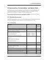
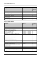
10 Accessories, Consumables, and Spare Parts .......................................................... 123
10.1 Standard Accessories ......................................................................................... 123
10.1.1
Corona Veo ................................................................................................ 123
10.1.2
Corona Veo RS .......................................................................................... 124
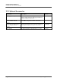
10.2 Optional Accessories ......................................................................................... 126
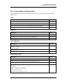
10.3 Consumables and Spare Parts ............................................................................ 127
11 Appendix .................................................................................................................... 129
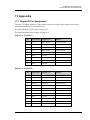
11.1
11.2
Digital I/O Pin Assignment................................................................................ 129
Internal Gas and Aerosol Flow Path Diagram ................................................... 132
12 Index........................................................................................................................... 133
Operating Instructions
Page iii
Charged Aerosol Detectors
Corona Veo and Corona Veo RS
Page iv
Operating Instructions
Charged Aerosol Detectors
Corona Veo and Corona Veo RS
1 Introduction
1.1 How to Use This Manual
The layout of this manual is designed to provide quick reference to the sections of interest
to the reader when operating the Thermo Scientific™ Dionex™ Corona™ Veo™ charged
aerosol detector. However, in order to obtain a full understanding of your detector, review
the manual thoroughly before beginning operation.
The descriptions in this manual apply to the following charged aerosol detectors:
•
Corona Veo
•
Corona Veo RS
The following conventions apply to the descriptions throughout this manual:
•
The term "the detector" or "the device" is used throughout the manual. If some detail
applies to only one detector version, the version is identified by name.
•
If not otherwise stated, the descriptions for the Viper™ capillary connections apply also
to the nanoViper™ and possible other Viper capillary connections.
•
The detector configuration may vary. Therefore, not all descriptions necessarily apply to
your particular detector.
•
The representation of a component in this manual may be different from the real
component. However, this does not influence the descriptions.
•
The descriptions in this manual refer to firmware version 1.01.
This manual is provided "as is". Every effort has been made to supply complete and
accurate information and all technical specifications have been developed with the utmost
care. The information contained in this manual should not be construed as a commitment
by Thermo Fisher Scientific. Thermo Fisher Scientific assumes no responsibility for any
errors that may appear in this document that is believed to be complete and accurate at the
time of publication and, in no event, shall Thermo Fisher Scientific be liable for incidental
or consequential damages in connection with or arising from the use of this document. We
appreciate your help in eliminating any errors that may appear in this document.
The information contained in this document is subject to change without notice.
All rights reserved, including those for photomechanical reproduction and storage on
electronic media. No part of this publication may be copied or distributed, transmitted,
transcribed, stored in a retrieval system, or transmitted into any human or computer language,
in any form or by any means, electronic, mechanical, magnetic, manual, or otherwise, or
disclosed to third parties without the express written permission of Thermo Fisher Scientific
Inc.
Operating Instructions
Page 1
Charged Aerosol Detectors
Corona Veo and Corona Veo RS
Trademarks
Empower is a registered trademark of Waters Corp.
PEEK is a trademark of Victrex PLC.
Windows and Windows Vista are registered trademarks of Microsoft Corp.
Torx is a registered trademark of Textron Industries Inc.
Nitronic is a registered trademark of AK Steel Corporation.
Simriz is a registered trademark of Carl Freudenberg KG.
All other trademarks are property of Thermo Fisher Scientific Inc. and its subsidiaries.
Page 2
Operating Instructions
Charged Aerosol Detectors
Corona Veo and Corona Veo RS
1.2 Safety
The CE Mark label and cTUVus Mark safety label on the rear panel indicate that the
detector is compliant with the related standards.
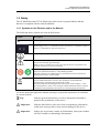
1.2.1 Symbols on the Detector and in the Manual
The following safety symbols are used on the detector:
Symbol
Description
˜
Alternating current—Courant alternatif
Power supply is on (-)—L'instrument est mis sous tension (-) and Power supply is
off (O)—L'instrument est mis hors tension (O)
Protective grounding—Mise à la terre de protection
Refer to the Operating Instructions to prevent risk of harm to the operator and to
protect the instrument against damage.
Référez-vous à ce manuel pour éviter tout risque de blessure à l'opérateur et/ou
protéger l'instrument contre tout dommage.
Label according to the "Measures for Administration of the Pollution Control of
Electronic Information Products" (China RoHS) guideline
Étiquette "Measures for Administration of the Pollution Control of Electronic
Information Products" (China RoHS)
WEEE (Waste Electrical and Electronic Equipment) label—For more information,
see the WEEE Information section in the "Installation and Qualification
Documents for Chromatography Instruments" binder.
Étiquette DEEE (Déchets d'Equipements Electriques et Electroniques) —Pour
plus d'informations, référez-vous au chapitre WEEE Information dans le classeur
"Installation and Qualification Documents for Chromatography Instruments".
At various points throughout the manual, messages of particular importance are indicated
by certain symbols:
Tip:
Indicates general information, as well as information intended to
optimize the performance of the device.
Important:
Indicates that failure to take note of the accompanying information
could cause wrong results or may result in damage to the device.
Important:
Indique que ne pas tenir compte de l'information jointe peut conduire
à de faux résultat ou endommager l'instrument.
Operating Instructions
Page 3
Charged Aerosol Detectors
Corona Veo and Corona Veo RS
Warning:
Indicates that failure to take note of the accompanying information
may result in personal injury.
Avertissement: Indique que ne pas tenir compte de l'information jointe peut entraîner
des blessures corporelles.
1.2.2 Safety Precautions
Tip:
Before initial operation of the detector, make yourself familiar with
the contents of this manual.
For the safety precautions in French, see page 7.
Warning:
All users of the device must observe the following safety precautions
and all additional safety precautions in this manual to avoid the
possibility of personal injury or damage to the device when
operating the device or carrying out any maintenance or service
procedures.
Observe any warning labels on the device and see the related
sections in these Operating Instructions.
•
Protective equipment
When performing any work on or near the HPLC system, wear personal protective
equipment (protective clothing, safety gloves, safety glasses) as required by the hazard of
the mobile phase and sample. For information about the proper handling of a particular
substance and for advice on specific hazards, refer to the material safety data sheet for the
substance you are using. Observe the guidelines of Good Laboratory Practice (GLP).
An eyewash facility and a sink should be close to the device. If any substance splashes on
the eyes or skin, wash the affected area and seek medical attention.
•
Hazardous substances
Many organic solvents, mobile phases, and samples are harmful to health. Be sure that
you know the toxic and infectious properties of all substances that you are using. You
may not know the toxic or infectious properties of many substances that you are using. If
you have any doubt about a substance, treat it as if it contains a potentially harmful
substance. For advice on the proper handling of a particular substance, refer to the Safety
Data Sheet (SDS) of the manufacturer. Observe the guidelines of Good Laboratory
Practice (GLP).
Dispose of waste substance in an environmentally safe manner that is consistent with all
local regulations. Do not allow flammable, toxic, and/or infectious substances to
accumulate. Follow a regulated, approved waste disposal program. Never dispose of
flammable, toxic, and/or infectious substances through the municipal sewage system.
Page 4
Operating Instructions
Charged Aerosol Detectors
Corona Veo and Corona Veo RS
•
Hazardous gases
Install the HPLC system in a well-ventilated laboratory. If the mobile phase or sample
includes volatile or flammable solvents, do not allow them to enter the workspace. If the
mobile phase or sample includes volatile or flammable solvents, avoid open flames and
sparks.
The exhaust gas may contain hazardous fumes. To avoid an accumulation of the exhaust
gasses, make certain that the exhaust gas is absorbed by a fume hood or other ventilating
device. Maintain a well-ventilated laboratory. Do not vent directly into the laboratory.
•
Electrostatic discharge
Discharge of electrostatic energy may lead to sparking and can constitute a fire hazard.
This effect is particularly pronounced in insulating capillaries und with non-conductive
solvents (for example, pure acetonitrile).
Take appropriate measures to prevent the generation of static electricity near the HPLC
system. For example, make sure that the air humidity level in the laboratory is
sufficiently high and provide proper ventilation, wear anti-static clothing or shoes,
prevent accumulation of air bubbles in waste lines, and use grounded waste containers.
Use only non-conductive capillaries to direct solvents into the waste container. With
electrically conductive capillaries, make sure that they are properly grounded.
•
Self-ignition of solvents
Do not use solvents for which the self-ignition temperature is below 150 °C. In case of
leakage, these solvents may self-ignite on a hot surface.
•
Capillaries, capillary connections, open connections
♦ Capillaries, especially non-metallic capillaries may burst, slip out of their fittings or
may not be screwed in. This may result in substances spraying out of the open
connections.
♦ In an UltiMate 3000 system, some components are made of PEEK™. This polymer
has superb chemical resistance to most organic solvents. However, it tends to swell
when in contact with trichlormethane (CHCl3), dimethyl sulfoxide (DMSO), or
tetrahydrofuran (THF). In addition, it is attacked by concentrated acids, such as,
sulfuric acid and nitric acid or a mixture of hexane, ethyl acetate, and methanol. In
both cases, capillaries may start leaking or they can burst. Swelling or attack by
concentrated acids is not a problem with brief flushing procedures.
♦ Do not use tubing that is stressed, bent, kinked, or damaged.
♦ Capillary connections can be contaminated by harmful substances or harmful
substances can escape from open connections.
♦ Always wear safety glasses when handling fused silica tubing, for example, during
installation or when cutting capillaries to the length.
•
Disconnect the detector from all power sources before removing the panels. When the
panels are removed, dangerous electrical connections will be exposed.
Operating Instructions
Page 5
Charged Aerosol Detectors
Corona Veo and Corona Veo RS
•
Always replace blown fuses with original spare part fuses authorized by Thermo Fisher
Scientific.
•
Replace faulty communication cables.
•
Replace faulty power cords. Never use a power cord other than the power cords provided
for the device.
•
Use only the original spare parts and accessories authorized for the device by Thermo
Fisher Scientific.
•
When operating the HPLC system, always set a lower pressure limit for the pump. This
prevents damage resulting from leakage or from running the pump dry.
•
To prevent damage to the detector when lifting or moving, always lift the unit by the
bottom sides or sides. Do not lift the detector by the bottom front or front panel door.
This may damage the door.
•
After operation, rinse out buffers and solutions that form peroxides.
•
Before switching from buffer to organic solution, rinse the analytical system thoroughly
with deionized or HPLC grade water.
•
When switching to another solvent, ensure that the new solvent is miscible with the one
contained in the HPLC system. If the solvents are not miscible, the system can be
damaged, for example, by flocculation.
•
If a leak occurs, turn off the detector immediately, stop the pump flow, and remedy the
situation.
•
Use only standard solvents (HPLC grade) and buffers that are compatible with all parts
that may be exposed to solvents.
•
Before interrupting operation for several days or more or when preparing the detector for
transport, observe the precautions for shutting down the detector (→ page 74).
•
Do not use the detector in ways other than those described in these Operating
Instructions.
•
Keep the operating instructions near the device to be available for quick reference.
Page 6
Operating Instructions
Charged Aerosol Detectors
Corona Veo and Corona Veo RS
1.2.3 Consignes de Sécurité
Si vous utilisez d'instrumentation analytique, vous devez connaître les risques d'utilisation
de produit chimiques.
Veuillez noter: Avant de commencer à utiliser l'instrument, assurez-vous que vous
vous êtes familiarisés avec le contenu de ce manuel.
Avertissement: Toutes les personnes utilisant l’instrument doivent observer les
consignes de sécurité suivantes pour éviter une mise en danger de sa
personne ou de dommage à l’instrument pendant l’utilisation et des
opérations de maintenance de l’instrument.
Observez les étiquettes d'avertissement sur l'instrument et référezvous aux sections correspondantes dans ce mode d'emploi.
•
Equipment de protection
Pour tous les travaux sur le système HPLC ou à proximité, portez l'équipement de
protection personnel (vêtements de protection, gant de sécurité, lunettes de protection)
qui correspond aux risque découlant de la phase mobile et/ou de l'échantillon. Pour les
informations sur la manipulation correcte des composés et des recommandations pour les
situations de risque spécifiques, veuillez consulter la fiche de données de sécurité des
substances que vous utilisez. Veuillez respecter des directives des Bonnes Pratiques de
Laboratoire (BPL).
Une installation permettant de se laver les yeux ainsi qu'un lavabo doivent se trouver à
proximité du système. Si une substance, quelle qu'elle soit, entre en contact avec vos
yeux ou votre peau, rincez abondamment la zone affectée à l’eau, puis.
•
Substances dangereuses
De nombreux solvants organiques, phases mobiles et échantillons sont nuisibles à la
santé. Informez-vous de propriétés toxicologiques et infectieuses de toutes les substances
que vous utilisez. Les propriétés toxicologiques et infectieuses de nombreuses substances
peuvent être mal connues. Au moindre doute concernant une substance, traitez-la comme
s'il contenait une substance potentiellement dangereuse. Pour des instructions comment
utiliser correctement des composés particuliers, veuillez consulter à la fiche de données
des sécurités du fabricant respectif. Veuillez respecter des directives des Bonnes
Pratiques de Laboratoire (BPL).
Débarrassez-vous de tous les déchets de substances de manière écologique,
conformément à la règlementation en vigueur au niveau local. Empêchez impérativement
l'accumulation de solvants inflammables, toxiques et/ou infectieux. Suivez un
programme d'élimination des déchets règlementé et approuvé. Ne jetez jamais de
solvants inflammables, toxiques et/ou infectieux dans le système municipal d'évacuation
des eaux usées.
Operating Instructions
Page 7
Charged Aerosol Detectors
Corona Veo and Corona Veo RS
•
Gaz dangereux
Installez le système HPLC dans un laboratoire bien ventilé. Si la phase mobile ou
l’échantillon contient des solvants volatils ou inflammables, vous devez assurer qu'ils ne
pénètrent dans l'espace de travail. Si la phase mobile ou l’échantillon contient des
solvants volatils ou inflammables, évitez les flammes nues et les sources d’étincelles à
proximité.
Le gaz d'échappement peut contenir des émanations dangereuses. Pour éviter une
accumulation des gaz d'échappement, assurez-vous que les gaz d'échappement sont
absorbés par une hotte ou autre dispositif d'aération.
•
Décharge électrostatique
Décharge électrostatique peut provoquer la formation d'étincelles et peut présenter un
risque d’incendie. Veuillez noter que des solvants fluides dans les capillaires peuvent se
charger automatiquement. Cet effet se peut produire particulièrement forte dans les
capillaires isolants et avec des solvants non-conducteurs (par exemple, l'acetonitrile pur).
Prenez des mesures appropriées pour éviter les charges électrostatiques à proximité du
système HPLC. Par exemple, s'assurez qu'il y a une humidité de l'air suffisante et une
ventilation adéquate dans le laboratoire, portez des vêtements ou équipement de
protection antistatique, évitez l'accumulation de bulles d'air dans les lignes de déchets et
utilisez des réservoirs à déchets mis à la terre.
Utilisez uniquement des capillaires non-conducteurs pour diriger solvants au réservoir de
déchets. Capillaires électriquement conducteur devrait être mis à la terre.
•
Inflammation spontanée des solvants
N’utilisez aucun solvants avec une température d‘auto-inflammabilité inférieure à
150° C. Si une fuite se produit, ces solvants peuvent s’auto-enflammer au contact d’une
surface chaude.
•
Capillaires, connecteur capillaires, connexions ouvertes
♦ Des capillaires, en particulier les capillaires non-métalliques, pourraient fendre ou
glisser des connecteurs ou ne peuvent pas être vissés. Ceci peut en résulter aussi que
des substances pourraient jaillir des connexions ouvertes.
♦ Dans un système UltiMate 3000, certaines composantes sont en PEEK. Bien que ce
polymère présente une excellente résistance chimique à la plupart des solvants
organiques, il a tendance à gonfler lorsqu'il est en contact prolongé avec du
chloroforme (CHCl3), du diméthyle sulfoxide (DMSO) ou du tetrahydrofuran (THF).
De plus, il est attaqué par des acides concentrés tels que l'acide sulfurique et l'acide
nitrique ou d'un composé du hexane, éthyle acétate et méthanol. Ceci peut causer des
capillaires de fuite ou risquer des capillaires d’éclater. Ces acides peuvent cependant
être utilisés dans le cadre de procédures de nettoyage, à condition que l’exposition soit
brève.
♦ N'utilisez pas de capillaires écrasés, pliés, abimés ou endommagés.
♦ Les connecteurs capillaires pour pourrait être contaminé par des substances
dangereuses ou des substances dangereuses pourrait sortir des connexions ouvertes.
♦ Portez des lunettes de protection lorsque vous manipulez des capillaires en silice
fondue (pendant l'installation, découpe, etc.).
Page 8
Operating Instructions
Charged Aerosol Detectors
Corona Veo and Corona Veo RS
•
Quand les capots de protection de l’appareil sont démontés, vous êtes exposés à des
connexions électriques sous haute tension deviennent accessibles. Débranchez
l'instrument de toute source d'alimentation électrique avant de retirer les capots. Ne
démontez les capots de protection que si cela est explicitement demandé au cours de ces
instructions.
•
Remplacez toujours les fusibles grillés par des fusibles de rechange autorisés par Thermo
Fisher Scientific.
•
Remplacez les câbles de communication défectueux.
•
Remplacez les cordons d'alimentation électrique défectueux. Utilisez uniquement les
cordons d’alimentation électrique spécifique à l’instrument.
•
Utilisez seulement des pièces de rechange originales et des accessoires autorisés par
Thermo Fisher Scientific.
•
Réglez toujours une limite de pression minimum pour la pompe HPLC. Ceci prévient les
dommages résultant de fuites ou de long-terme fonctionnement à sec de la pompe.
•
Lorsque vous soulevez ou l’instrument, tenez-le toujours par le dessous ou par les côtés de
l'unité. Soulever l’instrument par la partie avant inférieure ou par le panneau avant peut
endommager la porte.
•
Après utilisation, purgez le système des tampons et des susceptibles de former des
peroxydes.
•
Lorsque vous passez d’une solution saline à un solvant organique, effectuez un rinçage
intermédiaire du système HPLC à l'eau dé-ionisée ou qualité HPLC.
•
Lorsque vous passez à un autre solvant, assurez-vous que le nouveau solvant soit miscible
avec celui qui se trouve dans la pompe. Dans le cas contraire, la pompe peut être
endommagée; par exemple, par des floculations!
•
Si une fuite se produit, arrêtez immédiatement l’instrument, stoppez le débit de la pompe
et remédiez au problème.
•
Utilisez uniquement des solvants (qualité HPLC) et des solutions salines compatibles avec
les matériaux exposés phase mobiles.
•
De nombreux solvants organiques et solutions salines sont toxiques. Informez-vous des
propriétés toxicologiques de toutes les phases mobiles que vous utilisez.
•
Avant d'interrompre le fonctionnement pendant plusieurs jours ou plus, observez les
précautions figurant en page 74.
•
N'utilisez pas l'instrument de manière autre que celles décrites dans ce manuel.
•
Conservez ce manuel á proximité de l’instrument pour pouvoir le consulter facilement.
Operating Instructions
Page 9
Charged Aerosol Detectors
Corona Veo and Corona Veo RS
Page 10
Operating Instructions
Charged Aerosol Detectors
Corona Veo and Corona Veo RS
1.3 Intended Use
The device is designed to be operated only be qualified and authorized personnel. All users
must know the hazards presented by the device and the used substances.
The detector is designed for laboratory research use only in high-performance liquid
chromatography (HPLC) or ultra-high performance liquid chromatography (UHPLC)
applications. It is designed as part of the UltiMate 3000 system, but can also be used with
other HPLC systems if adequate control inputs and outputs are available. A PC with USB
port is required.
The detector can be controlled by the Chromeleon™ Chromatography Management System,
but it can also be operated with other data systems, such as
•
Xcalibur™.
To do so, installation of the DCMSLink (Thermo Scientific Dionex Chromatography Mass
Spectrometry Link) software is required in addition to the installation of the data system.
•
Empower™.
To do so, installation of the Thermo Scientific Dionex Instrument Integration Software is
required in addition to the installation of the data system.
For information about the availability of these and other data systems, contact the Thermo
Fisher Scientific sales organization for Dionex HPLC products.
Observe the following when using the detector:
•
The detector must be operated only with original accessories and spare parts as
recommended by Thermo Fisher Scientific and within the technical specifications
(→ page 121).
•
Use only standard solvents of at least HPLC grade or better solvent quality that are
compatible with all parts of the system that may be exposed to solvents. For information
about the wetted parts in the detector, see the 'Technical Information' section
(→ section 9, page 121). For information about the wetted parts in the other
UltiMate 3000 system modules, refer to the 'Technical Information' section in the
Operating Instructions for the UltiMate 3000 modules.
•
Use only volatile organic buffers. Avoid using inorganic buffer salts as mobile phase
modifiers, because they form non-volatile particles upon drying. This may result in loss
of performance and damage to the detector.
•
Note the special properties of the solvents, such as the viscosity, boiling point, UV
absorption (UV/Vis detector), refractive index (refractive index detector), dissolved gas
(degasser), as well as pH value.
•
In addition, observe the information about the solvent compatibility, buffer
concentrations and mobile phase requirements of the other system modules. For more
information, refer to the Operating Instructions for the respective modules.
Operating Instructions
Page 11
Charged Aerosol Detectors
Corona Veo and Corona Veo RS
If there is a question regarding appropriate usage, contact Thermo Fisher Scientific before
proceeding.
Warning:
If the device is used in a manner not specified by Thermo Fisher
Scientific, the protection provided by the device could be impaired.
Thermo Fisher Scientific assumes no responsibility and will not be
liable for operator injury and/or instrument damage. Whenever it is
likely that the protection is impaired, the instrument must be
disconnected from all power sources and be secured against any
intended operation.
Avertissement: Si l'instrument est utilisé de façon non spécifiée par Thermo Fisher
Scientific, la protection prévue par l'instrument pourrait être altérée.
Thermo Fisher Scientific n'assume aucune responsabilité et ne sera
pas responsable des blessures de l'operateur et/ou des dommages de
l'instrument. Si la protection de l'instrument n'est pas garanti à tout
moment, débranchez l'instrument de toutes les sources d'alimentation
électrique et assurez-vous que l'instrument n'est pas utilisé
involontairement.
Reference Documentation
In addition to this manual, it may be necessary to obtain information from other documents
for modules that you use in conjunction with the detector. These documents include (but are
not limited to):
•
Operating Instructions for the other modules of your system
•
Chromeleon 6.80 Chromatography Management System Help documents
•
If applicable
Operating Instructions for the gas supply (for example, nitrogen generator)
Page 12
Operating Instructions
Charged Aerosol Detectors
Corona Veo and Corona Veo RS
1.4 Federal Communications Commission (FCC) Note
This equipment has been tested and found to comply with the limits for a Class A digital
device, pursuant to part 15 of the U.S. FCC Rules. These limits are designed to provide
reasonable protection against harmful interference when the equipment is operated in a
commercial environment. This equipment generates, uses, and can radiate radio frequency
energy and, if not installed and used in accordance with the instruction manual, may cause
harmful interference to radio communications. Operation of this equipment in a residential
area is likely to cause harmful interference, in which case the user will be required to
correct the interference at his expense.
Operating Instructions
Page 13
Charged Aerosol Detectors
Corona Veo and Corona Veo RS
Page 14
Operating Instructions
Charged Aerosol Detectors
Corona Veo and Corona Veo RS
2 Overview
2.1 Unit Description
The detector is a modern high-quality instrument designed for HPLC, UHPLC and
microLC analyses, especially as part of the UltiMate 3000 system.
•
The detector uses charged aerosol detection (CAD) technology for liquid
chromatography. This technique enables detection of all non-volatile and many semivolatile analytes in the eluent.
•
The compound that is analyzed does not need to possess a chromophore as is the case
with UV detection. Also, the compound does not need to be ionized as is the case with
mass spectrometry.
•
The detector provides great sensitivity and a wide dynamic range. Under isocratic
conditions, non-volatile analytes produce similar response, independent of chemical
structure.
•
Fast data sampling ensures full compatibility with HPLC and UHPLC applications.
•
The concentric design of the FocusJet™ nebulizer provides an extended flow rate range.
In addition, the adjustable evaporation temperature optimizes analyte response.
•
Controlling the detector by the Chromeleon Chromatography Management System
provides a high degree of system integration, as well as maximum analysis efficiency due
to comprehensive data analysis and evaluation features in Chromeleon.
•
All parts that may be exposed to solvents are made of materials that provide optimum
resistance to the most commonly used solvents and buffer solutions in HPLC.
Operating Instructions
Page 15
Charged Aerosol Detectors
Corona Veo and Corona Veo RS
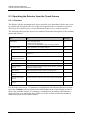
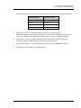
2.2 Detector Configurations
The detector is available in the following configurations:
Description
Part no.
Corona Veo
5081.0010
Corona Veo RS
5081.0020
Page 16
Operating Instructions
Charged Aerosol Detectors
Corona Veo and Corona Veo RS
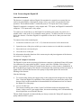
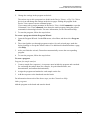
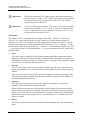
2.3 Operating Principle
The operating principle of the detector is based on charged aerosol detection. In charged
aerosol detection, the detector measures charge that is imparted to dried particles that are
formed from an ultra-fine aerosol of the analyte. The measured charged is proportional to
the amount of analyte in the sample.
1
2
4
3
6
9
10
5
8
7
Fig. 1: Schematic drawing of the operating principle
No.
Description
No.
Description
1
Mobile phase and analyte from column
6
Evaporation tube
2
Nebulizer
7
Mixing chamber
3
Gas inlet
8
Ion jet inlet
4
Spray chamber
9
Ion trap
5
Through drain pump to waste
10
Electrometer
The mobile phase with the analyte elutes from the column (no. 1) and is introduced into the
nebulizer (no. 2). Pressurized gas (no. 3) is introduced that has been passed through the
integrated gas filter. In the spray chamber (no. 4), the mobile phase with the analyte is
nebulized into an aerosol with the help of the pressurized gas. Large aerosol droplets are
removed from the detector by the drain pump (no. 5).
The resulting fine aerosol droplets pass through the evaporation tube (no. 6) that removes the
solvent and more volatile components. The remaining dried particles enter into the mixing
chamber (no. 7). The dried particles collide with a stream of ionized gas (no. 8) formed when
nitrogen passes over a corona wire. This leads to a diffusional charging of the aerosol
particles. The larger the particle, the higher is the level of charge that can be carried. The
particles that carry the charged nitrogen pass through an ion trap (no. 9).
Operating Instructions
Page 17
Charged Aerosol Detectors
Corona Veo and Corona Veo RS
In the ion trap excess charge is removed. The charge of the remaining aerosol particles is then
measured by the electrometer (no. 10). The greater the amount of analyte that enters the
detector and the larger the size of the particles formed, the greater is the charge that they can
carry and the larger the response the detector measures.
For a diagram of the gas and aerosol flow paths inside the detector, see section 11.2
(→ page 132).
Page 18
Operating Instructions
Charged Aerosol Detectors
Corona Veo and Corona Veo RS
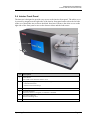
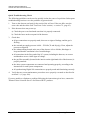
2.4 Interior Front Panel
The detector is designed to provide easy access to the interior front panel. The white cover
is secured by magnets on the right side of the interior front panel and a tab on the left side
of the cover that slides into a slot on the black front bezel. Remove the white cover on the
right side of the front panel to access the detector inlets and the leak sensor.
3
4
2
5
3
1
6
Fig. 2: Front view of the detector (here: Corona Veo RS)
No.
Description
1
LED 'Power'
The LED is blue when the detector is on.
2
Display with integrated touch screen, showing:
- General information
- Detector menu and settings
3
Capillary slots
4
FocusJet nebulizer
When the detector is shipped, no nebulizer is installed.
5
Corona Veo RS only
Stream-switching valve
6
Leak sensor
Operating Instructions
Page 19
Charged Aerosol Detectors
Corona Veo and Corona Veo RS
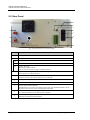
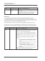
2.5 Rear Panel
9
1
8
7
2a
6
5
4
2b
2c
3
Fig. 3: Rear Panel (here: Corona Veo RS)
No.
Description
1
Cooling fan
2
Gas connections
2a
Gas exhaust
2b
Gas inlet
2c
Corona Veo only
Manual gas regulator knob
(For the Corona Veo RS, a plug is installed instead.)
3
Digital I/O consisting of 2 terminals with TTL inputs and relay outputs
For connection to external devices.
4
Fuse cartridge
Contains two slow-blow fuses rated at 1 A (5 x 20 mm).
5
Main power receptacle
6
Power switch
7
Analog signal output (optional)
Installable option to connect a suitable coaxial cable. For installation details, see the
Installation Instructions in the Analog Signal Output Kit.
8
USB port (USB 1.1 and 2.0 compatible)
To connect the detector to the data system computer.
9
Protective grounding
Indicates the functional earth terminal.
Page 20
Operating Instructions
Charged Aerosol Detectors
Corona Veo and Corona Veo RS
2.6 Flow Connections
The detector is designed to provide easy access to the capillary and tubing connections.
Open the cover on the right front side of the detector to access the liquid inlet. Slots at the
top and on the right side of the white front panel cover provide paths for capillary
connections to the system.
Tip:
The flow path between the column and the detector should be as small a
volume as possible (shortest capillary connection possible) to avoid peak
broadening effects and the accompanying loss of chromatographic efficiency.
2.7 Nebulizer
The detector is shipped without a nebulizer being installed. Install a nebulizer before
operation as described in the Installation Instructions for the nebulizer.
The FocusJet concentric nebulizer is the liquid inlet of the detector. Gas supplied by an
external gas source is directed to the nebulizer and merged with the incoming liquid from
the column to create an aerosol.
2.8 Manual Gas Regulator Knob (Corona Veo only)
The Corona Veo detector is equipped with a manual gas regulator. An adjustment knob on
the rear panel of the detector is used to regulate the internal gas pressure.
2.9 Stream-Switching Valve (Corona Veo RS only)
The Corona Veo RS is equipped with a 6-port 2-position stream-switching valve (SSV).
The SSV can be used to direct flow to the nebulizer or divert to external devices or waste.
To connect the stream-switching valve, see section 4.4.5 (→ page 40).
For further information about the operation of the stream-switching valve, see section 5.5.2
(→ page 64).
Operating Instructions
Page 21
Charged Aerosol Detectors
Corona Veo and Corona Veo RS
2.10 Leak Sensor
A leak sensor is located within the drip tray on the bottom right side of the front panel of
the detector for the automatic sensing of liquid leaks. If liquid collects in the drip tray
under the flow connections, the leak sensor reports a leak. A warning code appears on the
display.
Tip:
If you operate the detector from a chromatography data system, a warning code
will also be documented in the audit trail of the software.
When the leak sensor reports a leak, eliminate the cause for the leakage and dry the leak
sensor (→ page 112). If the sensor is not dry, the display continues to report the leakage with
a warning code on the display.
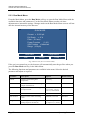
2.11 Detector Display
The detector is equipped with a liquid-crystal color display with integrated touch screen
designed for easy menu navigation. To operate the detector using the display, select the
soft-keys on the display for menu navigation.
For further information about the display and detector menu, see section 5.3 (→ page 48).
2.12 Self-Test Diagnostics and Preventive Maintenance
The detector supports several performance and reliability features:
•
Self-test diagnostics upon power-up (→ page 47)
•
Preventive maintenance (→ page 109)
•
Leak sensor (→ page 70)
•
Internal liquid sensor (→ page 70)
Page 22
Operating Instructions
Charged Aerosol Detectors
Corona Veo and Corona Veo RS
3 Installation
3.1 Facility Requirements
In addition to the facility requirements and safety information below, observe the
precautionary statements in section 1.2.2 (→ page 4).
Site Requirements
The installation site must meet the following requirements:
•
The main power switch and the main power receptacle are on the rear panel. Make sure
that
♦ Free and unrestricted access to the main power switch is ensured at all times.
♦ The power cord of the device can be easily reached and disconnected from the power
line at all times. Provide sufficient space behind the device to unplug the cable.
•
The installation site must meet the power and environmental specifications listed in the
'Technical Information' section (→ section 9, page 121).
•
Install the detector in the laboratory on a stable, flat surface that is free of vibrations.
•
The detector should have approximately 65 cm of linear bench space. The bench top
should be at least 65 cm deep.
•
Make sure that the surface is resistant to solvents.
•
Avoid locations with extreme changes in temperature, such as near air conditioning vents
or locations with air drafts.
•
Avoid locations with direct sunlight and high humidity.
•
Allow sufficient clearance behind and to the sides of the detector for easy access to
power connections, the main power switch, gas connections and ventilation. Maintain at
least a 15 cm clearance behind the detector from any vertical surface.
•
Install the detector in a location that provides access to a power outlet, nearby gas supply
and ventilation sources. Place the detector in a position such that all appropriate rear
panel connections to the system are possible.
•
An uninterruptible power supply (UPS) may be necessary for electrical lines that are
susceptible to large power fluctuations.
Operating Instructions
Page 23
Charged Aerosol Detectors
Corona Veo and Corona Veo RS
•
Connect the detector to an electrical line that shares a common ground with other system
modules. If necessary, use a properly functioning multiple socket. A common ground for
all system modules will avoid ground loops which can create erratic results (for example,
high baseline noise).
Warning:
Do not use defective multiple sockets or extension cords, as
they may cause personal injury or damage to the device.
Avertissement:
N'utilisez pas des défectueux blocs multiprise ou des câbles
prolongateurs. Cela pourrait entraîner des blessures
corporelles ou endommager l'instrument.
Ventilation Requirements
•
•
Ventilation must be at atmospheric pressure with no vacuum or negative pressure
applied.
Important:
A vacuum in the ventilation may cause depressurization
inside the detector. This may impair detector operation and
lead to decreased performance.
Important:
Un vide dans la ventilation peut conduire à la
dépressurisation à l'intérieur du détecteur. Ceci peut nuire au
bon fonctionnement du détecteur et contribuer à une
diminution des performances.
Install the HPLC system in a well-ventilated laboratory. Exhaust gases (including carrier
gas, vaporized eluents and solute micro particles) exit on the rear panel of the detector
through an external vent. The exhaust gas may contain volatile organic compounds in
low concentration. Connect the gas exhaust to a fume hood or other ventilation device
and the detector is properly vented. Observe the safety precautions on hazardous gases in
section 1.2.2 (→ page 4).
Page 24
Operating Instructions
Charged Aerosol Detectors
Corona Veo and Corona Veo RS
Gas Supply Requirements
Important:
To prevent damage to the detector, do not exceed the maximum gas
pressure of 550 kPa (80 psig) for the gas supply.
Important:
Ne pas dépasser une pression de gaz maximaux de 550 kPa (80 psig)
pour l'approvisionnement en gaz.
•
If you work with combustible solvents, use nitrogen gas. Higher purity nitrogen is not
required but recommended and should be dry (not containing water vapor). Medicalgrade nitrogen from an in-house liquid nitrogen source is sufficient. However, filter the
supplied gases through a submicron particle filter before they enter the detector. Not
using a well-filtered operating gas supply may increase the baseline noise.
•
Observe the following notes:
♦ The inlet gas must be clean and free from micro particles (size ≤ 0,1 µm).
♦ The inlet gas supply pressure must be between 480 – 550 kPa (70 – 80 psig).
♦ The gas consumption of the detector is approximately 4 L/min.
•
Pressure variations in which the gas supply drops below 480 kPa (70 psig) may result in
loss of performance. Monitor the gas supply pressure during the installation.
Operating Instructions
Page 25
Charged Aerosol Detectors
Corona Veo and Corona Veo RS
3.2 Unpacking the Detector
All electrical components of the detector are carefully tested before the module is shipped
from the factory. After unpacking the detector, inspect the module for any signs of
mechanical damage, which might have occurred during transit.
Tips: Immediately report any shipping damage to both, the incoming carrier and
Thermo Fisher Scientific. Shipping insurance will compensate for the damage
only if reported immediately.
Keep the original shipping container and packing material. They provide
excellent protection for the module in case of future transit. Shipping the
module in any other packaging automatically voids the product warranty.
1.
Open the packaging box of the detector and remove the accessories kit and power
cord. Some accessories may be shipped in a separate box.
The scope of delivery comprises:
♦ Detector
♦ Accessories kit
♦ Nebulizer
♦ Power connection cable
♦ Operating Instructions
2.
Grasp the detector by the sides. Slowly and carefully, pull the detector out of the
shipping container and place it on a stable surface.
Important:
To prevent the detector from falling, grasp the detector by the
sides, and then lift the detector together with the foam spacers
out of the shipping container. Do not lift the module by the
foam spacers and not by the front panel doors.
Important:
Afin d'empêcher l'instrument de tomber, saisissez-la par les
côtés. Ne soulevez l'instrument e à l’aide du matériau
d'emballage ou par les portes des panneaux avants.
3.
Remove the foam spacers, and then remove the polythene packaging.
4.
Before connecting the detector to the power source, allow the module to come to room
temperature and to allow any condensation that might have occurred during shipping
to evaporate.
Page 26
Operating Instructions
Charged Aerosol Detectors
Corona Veo and Corona Veo RS
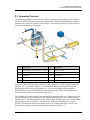
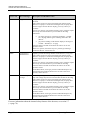
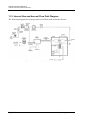
3.3 Positioning the Detector in an UltiMate 3000 System
If the detector is part of an UltiMate 3000 system, for example for analytical HPLC
applications, stack the individual modules and interconnect them on the rear panel as
shown in the example in Fig. 4.
Solvent
rack
(optional)
Pump
Autosampler
Column
compartment
Detector
Fig. 4: Example for stack arrangement and rear panel connections
in an UltiMate 3000 system with the Corona Veo RS detector
Observe the following when positioning the detector:
•
The arrangement of the system modules depends on the application and may vary if an
optical detector is used additionally.
•
Place the detector in a position so that the connections between the output of the column
and the inlet of the detector are minimized. This will reduce post-column band
broadening effects and optimize chromatographic resolution.
•
In an UltiMate 30000 system, apart from the Solvent Rack, all system modules can be
connected separately to the computer via the USB port on the rear panel of the module,
respectively. However, Thermo Fisher Scientific recommends interconnecting all
modules, and then connecting the system to the computer with only one connection.
Operating Instructions
Page 27
Charged Aerosol Detectors
Corona Veo and Corona Veo RS
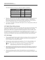
Systems with Series and Parallel Detector Configuration
The detector can be used in series or parallel configuration with other detectors (for example,
a UV detector or mass spectrometer).
Series Configuration
In series configuration, one flow path from the pump is used for each type of detector
installed on the system. Consider the following:
•
In general, charged-aerosol detectors such as the Corona Veo detector must be placed last
in the flow path within the system.
•
The addition of other detectors may contribute to band broadening, and have an adverse
effect on peak shape measured by the detector.
Parallel Configuration
In parallel configuration with another detector or a mass spectrometer, consider the following:
•
Use a flow splitter to ensure balanced distribution of liquid flows to each detector in the
system.
Tip:
•
Thermo Fisher Scientific recommends using an adjustable analytical flow
splitter (part no. 70-6377, adjustable from 1:1 to 20:1) for flexible,
accurate and precise liquid flow.
When you use a passive flow-splitting device and thus adjust (balance) the liquid flows,
consider the backpressure from the detector. Observe the flow rate specifications in the
'Technical Information' section (→ section 9, page 121).
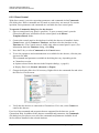
Page 28
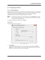
Operating Instructions
Charged Aerosol Detectors
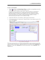
Corona Veo and Corona Veo RS
3.4 Connecting the Detector Rear Panel
3.4.1 Overview of Connections
The rear panel connections depend on the system configuration. The following overview is
to assist you with the required connections:
•
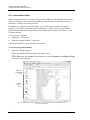
USB connection
Connect the USB port to
♦ Use the detector with other system modules, such as UltiMate 3000 modules.
– and/or –
♦ Connect the detector to a data system computer via USB port and operate it from
chromatography software, such as Chromeleon.
•
Digital I/O connection
Connect the Digital I/O port to
♦ Connect a pump to the detector within an HPLC system, such as the UltiMate 3000
system, and establish the 'Pump Off' connection.
– and/or –
♦ Connect the detector to other external devices.
•
Analog signal output connection
Use and install the analog signal output to use the detector with a data system computer if
no USB port is available on the computer.
3.4.2 Connecting the Power Cord
Use the power cord shipped with the device to connect the detector to the main power
source. Connect the power cord from the main power receptacle on the rear panel. No
manual adjustment is required to adapt the line voltage to local voltage requirements.
Warning:
Never use a power cord other than the power cords provided for the
device.
Do not use defective multiple sockets or extension cords, as they
may cause personal injury or damage to the device.
Avertissement: Utilisez uniquement les cordons d’alimentation électrique spécifique
à l’instrument.
N'utilisez pas des défectueux blocs multiprise ou des câbles
prolongateurs. Cela pourrait entraîner des blessures corporelles ou
endommager l'instrument.
Operating Instructions
Page 29
Charged Aerosol Detectors
Corona Veo and Corona Veo RS
3.4.3 Connecting the USB Cable
Connect the detector to the data system computer via the USB port on the rear panel. To
ensure trouble-free operation, use only the cables shipped with the detector. The PC must
be equipped with a USB 1.1 or USB 2.0 port.
The following cable is available (provided in the accessories kit for the detector):
USB Cable
Part no.
USB cable, type A to type B, high speed, USB 2.0 compatible (cable length: 3 m)
70-5713
Tip:
The USB standard limits the USB cable length to 3 meters. Each USB device
can be separated from the PC or next USB hub by no more than 3 meters
The following connection options are available:
•
Connect the detector directly to the USB port on the computer.
•
If you use the detector in an UltiMate 3000 system
Connect the detector to an internal USB hub on the pump of the UltiMate 3000 series
(except LPG-3400XRS pump*). Thermo Fisher Scientific recommends connecting all
modules to the pump, and then connecting the system to the computer via only one
connection. If the system includes a UV detector in addition to the detector, connect the
UV detector directly to the computer.
* The LPG-3400XRS pump is not equipped with a USB hub.
Tips: It is not possible to use the USB hub on the UltiMate 3000 autosampler for
connection of the detector to the computer.
The detector has no USB hub on its rear panel. Thus, it can only be
connected to USB hubs of other modules in the UltiMate 3000 system or
directly to the computer.
•
If you want to operate the detector from Chromeleon chromatography software
Verify that Chromeleon is installed on the computer and that the license code is entered
before you connect the detector to the USB port on the Chromeleon computer and turn on
the detector power. Only if you install Chromeleon first, the USB driver for the detector
is automatically loaded and the Windows® operating system can detect the detector upon
power-up.
For further information about operation from Chromeleon, see section 6 (→ page 77).
Page 30
Operating Instructions
Charged Aerosol Detectors
Corona Veo and Corona Veo RS
3.4.4 Connecting the Digital I/O
General Information
The detector is equipped with two Digital I/O terminals for connection to external devices
(such as an autosampler, a data station, pumps, valves, etc.) which can synchronize their
operation. The terminals include 7 connection ports (4 TTL inputs and 3 relay outputs).
Digital I/O terminal A comprises 2 relay outputs and 1 TTL input, and Digital I/O terminal B
comprises 3 TTL inputs and 1 relay output.
To connect an external device to the Digital I/O terminal ports on the rear panel, use a
suitable cable, such as the I/O 2-conductor cable (part no. 70-4850) from the accessories
kit for the detector. Check the Digital I/O capabilities of the device that you want to the
detector.
To connect wires to the terminal ports:
1.
Locate the screwdriver (size 3/32" x 2") from the accessories kit for the detector.
2.
Open the screw of the pin to which you want to connect a wire with the screwdriver.
3.
Insert the loose wire into the pin.
4.
Close the screw of the pin.
For information about the functions of the connector pins and pin assignment of the detector,
see section 11 on page 129.
'Pump Off' Output Connection
The Digital I/O port on the rear panel of the detector comprises a dedicated 'Pump Off' output
for connection to a pump within an HPLC system, such as the UltiMate 3000 system. If a
pump is connected to the 'Pump Off' output on the detector, a safety feature is established. In
the event that the gas supply to the detector is interrupted, this connection will be activated. A
signal will be sent from the detector to the pump to stop mobile phase flow and avoid
flooding of the detector.
Note the following:
•
To use this safety feature, the support relay on the pump must be designed to stop liquid
flow. Check the Digital I/O capabilities of the pump before you connect the pump to the
detector. Refer to the manufacturer's documentation for information on how to connect
the Digital I/O of the pump.
•
Corona Veo RS only
The stream-switching valve of the Corona Veo RS detector has an integrated safety
feature. In the event of a gas supply failure, the stream-switching valve will automatically
divert liquid flow away from the detector.
Thermo Fisher Scientific recommends that you always connect the 'Pump Off' output to the
pump within an HPLC system.
Operating Instructions
Page 31
Charged Aerosol Detectors
Corona Veo and Corona Veo RS
For further information about connecting an UltiMate 3000 pump (except for the
LPG-3400XRS pump) to the 'Pump Off' output, refer to Chromeleon Help. For information
about connecting an LPG-3400XRS pump to the 'Pump Off' output, refer to the Operating
Instructions for the LPG-3400XRS pump.
3.4.5 Connecting the Analog Signal Output
The analog signal output carries a signal from 0-1 V that is proportional to the current that
is being measured. The analog signal output is available as an installation option when
digitalized data output over the USB port to a compatible chromatography software is not
available. The analog signal output uses a BNC connector (Bayonet Neill-Concelman).
For information about installation and connection of the analog signal output, see the
Installation Instructions in the Analog Signal Output Kit.
Page 32
Operating Instructions
Charged Aerosol Detectors
Corona Veo and Corona Veo RS
4 Preparation for Operation (Startup)
4.1 Overview of Actions
After you have unpacked, positioned and connected the detector as described in
sections 3.1 through 3.4 (→ page 23 and following), prepare the detector for operation.
Follow the sequence of steps below:
1.
Connect the drain tubing as described in section 4.2 (→ page 34).
2.
Connect the gas tubings to the gas inlet and the gas exhaust as described in section 4.3
(→ page 35).
3.
Install the nebulizer as described in the Installation Instructions for the nebulizer.
4.
Make the flow connections from the detector to the other modules of your system, as
required by your application. For information about the flow connections, see
section 4.4 (→ page 36).
5.
Turn on the detector. Observe the notes and precautions in section 5.2 (→ page 47).
Allow the detector to perform the self test before proceeding.
6.
Chromeleon installation (optional)
When the display shows the Main Menu after the self test, set up the detector in
Chromeleon as described in section 6.1 (→ page 78).
7.
If required
Adjust the brightness of the detector display (→ section 5.3.2, page 49).
8.
If required
Set date and time on the detector display (→ section 5.3.4.2, page 57).
9.
Set the gas pressure for the nebulizer as described in section 5.4.1 (→ page 59).
10. Before using the detector for sample analysis, prepare the LC system and the detector
as described in sections 5.4.2 and 5.4.3 (→ starting from page 62).
Operating Instructions
Page 33
Charged Aerosol Detectors
Corona Veo and Corona Veo RS
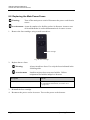
4.2 Connecting the Drainage
The detector has two drain ports at the bottom right of the enclosure to collect liquid leaks
or waste from the detector. Use the drain tubing shipped with the detector to direct liquid
from the two drain ports to waste.
2
1
Fig. 5: Drain ports
No.
Description
1
Leak port
For liquid leaks from the drip tray.
2
Waste port
For liquid from the drain pump during operation.
When connecting the drain ports of the detector, observe the following:
•
Connect the ports separately with a drain line for each port. Do not use a connection tube
to connect both ports with each other.
•
Both drain ports may be directed to the same waste.
•
Use the elbow and tee pieces from the accessories kit for the detector to connect the drain
ports.
•
Make sure that the tubing and waste bottle are below the height of the detector.
Drainage in an UltiMate 3000 system
In an UltiMate 3000 system, you can use the components from the drain kit for
UltiMate 3000 systems to direct liquid leaks to waste via the drain system. The kit is
shipped with the UltiMate 3000 pumps and can be ordered separately (part no. 6040.0005).
The kit includes all required components and detailed installation instructions.
If there is more than one UltiMate 3000 detector in your system and you need an additional
tee piece, you can find one in the accessories kit of the UltiMate 3000 fluorescence,
multiple wavelength, or diode array detector.
Page 34
Operating Instructions
Charged Aerosol Detectors
Corona Veo and Corona Veo RS
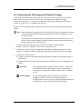
4.3 Connecting the Gas Supply and Exhaust Tubing
Connect the gas and exhaust tubing from the accessories kit to the gas inlet and exhaust
outlet at the rear of the detector. Observe the gas requirements and precautionary
statements in section 3.1 (→ page 23) and the gas supply and ventilation guidelines in
section 4.5.3 and 4.5.4 (→ starting from page 42).
If required, use the tubing cutter from the accessories kit to cut the tubing to appropriate
length.
Tips: Make straight cuts perpendicular to the length of the gas inlet tubing for a good
connection to the push-in fitting on the gas inlet. Slanted or angular cuts can
lead to gas leaks.
If you wish to use a different gas inlet tubing with metric dimensions, you can
use the inch-to-metric adapter from the detector accessories kit to connect the
tubing to the gas inlet of the detector.
1.
Locate the gas inlet tubing (part no. 6081.1070) and the exhaust tubing
(part no. 70-6261) from the accessories kit for the detector.
2.
Connect one end of the gas inlet tubing to the push-in fitting on the gas inlet of the
detector. Connect the other end of the gas inlet tubing to the outlet of the gas supply.
3.
Connect the exhaust outlet:
a) Connect one end of the exhaust tubing to the push-in fitting of the exhaust output of
the detector.
b) Connect the other end of the exhaust tubing to a fume hood or other ventilating device
source.
Warning:
The exhaust gas may contain hazardous fumes. To avoid an
accumulation of the exhaust gasses, make certain that the
exhaust gas is absorbed by a fume hood or other ventilating
device.
Avertissement:
Le gaz d'échappement peut contenir des émanations
dangereuses. Pour éviter une accumulation des gaz
d'échappement, assurez-vous que les gaz d'échappement sont
absorbés par une hotte ou autre dispositif d'aération.
Operating Instructions
Page 35
Charged Aerosol Detectors
Corona Veo and Corona Veo RS
4.4 Making Flow Connections
The following section provides information about how to connect capillaries to your
detector.
4.4.1 General Guidelines
When connecting capillaries to the detector, observe the following general precautions:
•
Observe the precautionary statements for capillaries and capillary connections in
section 1.2.2 (→ page 4).
•
When you connect capillaries, make sure that the connectors are free from contaminants.
Even minute particles may cause damage to the system.
•
Use only the capillaries shipped with the detector or original spare capillaries.
•
Always make sure that the ID of the replacement capillary corresponds to the ID of the
capillary shipped with the system.
•
Make sure that the connectors and capillary ends are free from contaminants and not
damaged. Even minute particles may cause damage to the system, for example, to the
nebulizer and, with the Corona Veo RS, the stream-switching valve.
•
The connection between the column and the detector should be as short as possible to
prevent band-broadening.
For more information about the available capillaries, see section 10.2 (→ page 126).
Page 36
Operating Instructions
Charged Aerosol Detectors
Corona Veo and Corona Veo RS
4.4.2 Capillary Connections in an UltiMate 3000 System
Note the following:
•
Different fitting systems are used in an UltiMate 3000 system. Therefore, install the
capillaries and fittings only at the positions for which they are intended.
•
Viper and nanoViper fitting connections
Loosen or tighten the Viper connection only using the black knurled screw and only with
your hand (do not use tools). The knurled screw can be easily removed and reattached to
the capillary at any time. If you observe leakage on the connection, tighten the screw a
little further. If leakage continues, remove the capillary, clean the capillary ends carefully
by using a cloth or tissue wetted with isopropanol, and reinstall the capillary. If the
connection continues to leak, replace the Viper capillary.
When connecting the Viper capillary to the detector inlet, observe the guidelines in the
Installation Instructions shipped with the capillary.
Capillaries with Viper fitting connections can be reused also for a different connection.
•
Conventional fitting connections (non-Viper)
Do not over-tighten these fitting connections. If you observe leakage on the connection,
tighten a little further.
If leakage still exists, first consider cleaning the connection port with a cleaning swab
(part no. 6040.0006). Replace the capillary and/or fitting if this does not eliminate the
problem.
Reuse used fittings and ferrules only for the same capillary connection. This is to avoid
increased dead volume or damage to the system and leakage.
Operating Instructions
Page 37
Charged Aerosol Detectors
Corona Veo and Corona Veo RS
4.4.3 Installing the In-Line Filter (optional)
An in-line filter is included in the accessories kit for the detector. The in-line filter can be
used in the flow path before the detector to prevent particulate matter from entering into
the nebulizer.
To install the in-line filter:
1.
Locate and unpack the in-line filter. The in-line filter is shipped with a filter frit.
2.
Open the two end nuts of the filter assembly.
3.
Rinse the filter housing with deionized water.
4.
Install and close one end nut.
5.
Insert the filter frit into the filter housing. Ensure that the filter frit is properly centered
and seated against the surface of the end nut. Be careful not to scratch the filter.
6.
Install the second end nut and tighten it carefully until contact between the cap and
filter is felt. The filter is properly installed if both end nuts are approximately an equal
distance from the center of the filter housing. The connection should be fingertight. Do
not use a wrench or pliers to close the end nuts. Do not overtighten the end nuts, as
this can crush the filter.
7.
Connect the in-line filter to the system flow path as described in section 4.4.4
(→ page 39). Ensure that the in-line filter is installed in the direction of flow as
indicated on the filter.
Page 38
Operating Instructions
Charged Aerosol Detectors
Corona Veo and Corona Veo RS
4.4.4 Connecting Capillaries to the Detector
To connect the detector to the system flow path:
1.
Locate the red capillary and the RheFlex fittings from the accessories kit for the
detector.
2.
Connect one end of the red capillary to the column outlet using a fitting.
3.
If you use the in-line filter
a) Connect the capillary from the column outlet to the upstream end of the in-line filter.
Ensure that the direction of flow is as indicated on the filter housing.
b) Flush the in-line filter with mobile phase at a flow rate of about 5 mL to waste.
c) Connect a capillary to the downstream end of the in-line filter.
4.
Remove the white cover on the right front side of the detector.
5.
Connect the other end of the red capillary to the fluid inlet of the detector using a
fitting. This step depends on the detector model:
♦ Corona Veo:
Connect the capillary to the nebulizer.
♦ Corona Veo RS:
If you use the stream-switching valve: Connect the capillary to the Inlet port (Port 3)
of the stream-switching valve. Connect the other capillaries to the ports on the streamswitching valve as described in section 4.4.5.
If you do not use the stream-switching valve: Connect the capillary to the nebulizer.
After you have made the capillary connections to the detector, you can re-install the white
cover on the front panel.
Operating Instructions
Page 39
Charged Aerosol Detectors
Corona Veo and Corona Veo RS
4.4.5 Connecting the Stream-Switching Valve (Corona Veo RS only)
To connect the stream-switching valve, connect ports 2, 3 and 4 of the valve. The ports of
the stream-switching valve are assigned as follows:
5
4
6
No.
3
1
Ports
2
Divert/Waste (away from the
detector)
3
Inlet (capillary from column)
4
Nebulizer (to nebulizer inlet)
2
Fig. 6: Ports on the stream-switching valve
1.
Make sure that you have connected the detector to the flow path as described in
section 4.4.4 before you proceed.
2.
Locate the Viper capillary, the gray capillary and the RheFlex fittings from the
accessories kit for the detector.
3.
Connect the Viper capillary from the Nebulizer port (Port 4) on the stream-switching
valve to the nebulizer inlet using the RheFlex fittings.
4.
Connect the gray capillary to the Divert/Waste port (Port 2) using a RheFlex fitting
and direct it to the waste.
Page 40
Operating Instructions
Charged Aerosol Detectors
Corona Veo and Corona Veo RS
4.5 General Guidelines for Detector Operation
The following sections offer general guidelines for detector operation.
4.5.1 Mobile Phase
Mobile phase quality significantly affects detection limits and detector performance. A careful
consideration in the selection of the components of the mobile phase will be extremely useful
in minimizing baseline noise and optimizing the performance during analysis. This section
describes general guidelines for the use of the mobile phase with the detector.
To ensure optimal performance of the detector, observe the following guidelines:
•
Prepare all mobile phases with HPLC-grade (or better) solvents- and reagent-grade
chemicals.
Tip:
It is recommended to use water from an ultra-pure deionized source, which
typically has low conductivity and high resistivity.
•
Use only mobile phases that contain water, solvents and modifying reagents of the
highest purity available.
•
The stability of the mobile phase may decrease over a period of time. Use freshly
prepared mobile phase on a daily basis.
Tip:
It is recommended to use online degassers for HPLC systems with the
detector. In some cases, it may be necessary to use helium sparging and/or
sonication during mobile phase preparation in order to achieve optimum
results.
•
Take care to minimize non-volatile particulates and/or additives from the mobile phase.
The detector will produce a response to non-volatile particulate matter contained in the
mobile phase.
•
Use solvents with minimal residue after evaporation. If a particular solvent causes
problems due to particulates, try a different grade or a different vendor. Be aware that
some solvents contain stabilizing agents that may cause elevated baseline noise.
•
When you change from a buffer to a different operating mobile phase, be sure the
solvents are miscible and will not induce precipitation of the buffers.
•
Only use volatile mobile phase additives (buffers, solvents, etc.). Buffers such as acetic
or formic acid and their ammonium salts are typical. Use additives (e.g. trifluoroacetic
acid (TFA, HFBA)) at concentrations below 0.3 %. Avoid using carbonates,
bicarbonates, sulfates, phosphates or other non-volatile buffers.
Operating Instructions
Page 41
Charged Aerosol Detectors
Corona Veo and Corona Veo RS
The following table is to assist you with typical additives and buffers.
Additive/Buffer
pKa
Buffer Range
Trifluoroacetic Acid (TFA)
0.3
Formic Acid
3.75
2.8 – 4.8
Ammonium Formate
3.75
2.8 – 4.8
Acetic Acid
4.76
3.8 – 5.8
Ammonium Acetate
4.76
3.8 – 5.8
•
Exposure of the detector to non-volatile salts will lead to increased background currents
and noise. It may also adversely affect the nebulizer performance. If the detector is
inadvertently exposed to non-volatile salts, use HPLC-grade water as mobile phase to
remove the salts from the detector. Avoid using inorganic buffer salts.
•
Use nitrogen with highly combustible mobile phases such as tetrahydrofuran (THF) and
other ethers or ketones.
4.5.2 Mobile Phase Delivery System
The pump should deliver continuous flow and at the same time ensure the intermixing of the
mobile phase (if gradient elution is used). Fluctuations in pump backpressure can cause
baseline noise. If the noise is synchronized with the pump stroke, check your HPLC pump.
The mobile phase reservoir should be glass. In some applications, however, it may be
necessary to use plastic solvent reservoirs. In carbohydrate applications, for example, PTFE
solvent reservoirs should be used to prevent carbon dioxide build up in the mobile phase.
4.5.3 Gas Supply
•
The gas supplied to the detector must be either air or nitrogen. Always use nitrogen with
tetrahydrofuran (THF) or other highly combustible solvents. Do not use helium, as it
does not charge the aerosol particles properly.
•
If nitrogen gas is used, it must be pure (typically ≥ 95 %), free from particulates, and
must not contain volatile hydrocarbons or solvent vapors (e.g. compressor oils).
Tip:
If necessary, use a sub-micron filter in combination with a water
condensation trap located close to the nitrogen gas source.
•
The supplied gas is filtered through a charcoal filter and a high-efficiency particulate air
(HEPA) filter within the detector. Make sure that the filters are maintained properly to
ensure optimal gas quality.
•
If you use a nitrogen generator, observe the manufacturer's user documentation on
recommended service intervals for the generator to provide optimum performance of the
detector.
Page 42
Operating Instructions
Charged Aerosol Detectors
Corona Veo and Corona Veo RS
4.5.4 Ventilation
Important:
Volatile hydrocarbons such as compressor oils in the external gas
supply to the detector may cause permanent damage to the detector.
Important:
Hydrocarbures volatils tels que les huiles pour compresseur dans
d'approvisionnement en gaz extérieurs peuvent causer des dommages
permanents au détecteur.
•
Maintain a well-ventilated laboratory. Exhaust gases must be vented to an appropriate
hood or gas ventilating device. Do not vent directly into the laboratory.
•
Operate the detector only when the exhaust vent is connected properly. Exhaust gas
venting should be at atmospheric pressure. A vacuum or restriction may result in pressure
changes within the detector which may lead to baseline instability and/or other problems.
•
The use of bottled or liquid nitrogen cylinder gas may be a quick and easy source of
nitrogen during the installation. However, for uninterrupted use, a nitrogen generator is
recommended.
Operating Instructions
Page 43
Charged Aerosol Detectors
Corona Veo and Corona Veo RS
Page 44
Operating Instructions
Charged Aerosol Detectors
Corona Veo and Corona Veo RS
5 Operation
5.1 Safety Guidelines for Operation
English Safety Guidelines
For the safety guidelines in French, see page 46.
Important:
When operating the detector, observe the following safety
guidelines:
•
Always turn on the gas supply before starting the flow of mobile phase.
•
When you stop the gas flow, always turn off the mobile phase flow and allow the
detector to remain pressurized for 5 minutes before your turn off the gas flow.
•
Turn on the gas flow only when a nebulizer is installed.
•
Observe the pressure range for the gas supply (→ section 9, page 121) and the internal
gas pressure setting as stated in the Installation Instructions for the nebulizer.
•
Operate the detector only when it is connected to appropriate ventilation. Exhaust gas
ventilation should be at atmospheric pressure.
•
If a leak occurs, turn off the detector immediately, stop the pump flow, and remedy the
situation.
•
If the pressure relief valve is open and leaking gas, immediately shut down the detector.
For details, see section 5.7.3 (→ page 71).
•
After operation of the detector
If you operated the detector with organic solvents in high concentration that may form
peroxides upon evaporation (un-stabilized THF, 2-propanol, etc.), flush the flow paths
completely with HPLC-grade water prior to shut down.
Operating Instructions
Page 45
Charged Aerosol Detectors
Corona Veo and Corona Veo RS
French Safety Guidelines
Important:
Lors de l'exploitation et l'entretien du détecteur, respectez les
consignes de sécurité suivantes:
•
Toujours couper l'alimentation en gaz avant de commencer le débit de la phase mobile.
•
Lorsque vous arrêtez le flux de gaz, toujours désactiver le flux de la phase mobile et
permettre le détecteur de rester sous pression pendant 5 minutes avant votre arrêt le débit
de gaz.
•
Activez le débit de gaz uniquement lorsqu'un nébuliseur est installé.
•
Respecter la gamme de pression de l'alimentation en gaz (→ section 9, page 121) et la
réglage de la pression interne de gaz selon les instructions de montage pour le nébuliseur.
•
Utilisez le détecteur uniquement lorsqu'il est connecté à une ventilation appropriée.
Évacuation des gaz doit être à la pression atmosphérique.
•
Si une fuite se produit, arrêtez immédiatement l’instrument, stoppez le débit de la pompe
et remédiez au problème.
•
Si la soupape de décharge est ouverte et fuit de gaz, immédiatement l'arrêt du détecteur.
Pour les détails voir section 5.7.3 (→ page 71).
•
Après l'utilisation du détecteur
Si vous utiliser le détecteur avec des solvants organiques en haute concentration qui
peuvent former des peroxydes au cours de l'évaporation (THF non stabilisée,
isopropanol), rincez les chemins d'écoulement complètement avec l'eau de qualité CLHP
avant de vous arrêter le détecteur.
Page 46
Operating Instructions
Charged Aerosol Detectors
Corona Veo and Corona Veo RS
5.2 Turning on the Power to the Detector
Before powering up the detector, be sure that all preparations for startup have been carried
out (→ section 4, page 33).
To start the detector for the first time, turn on the main power switch on the rear panel of
the detector.
The following sequence of events occurs when the detector is powered up:
•
Self-test diagnostics
The detector runs a series of internal tests. During these self-diagnostics, all of the main
components are checked. When testing is complete and has been successful, the display
will show the start up screen with the current detector firmware version, followed by the
warm-up screen.
•
Warm-up phase
In the warm-up state, the detector monitors the internal temperature of the components.
The warm-up time may be longer if the ambient temperature is cool or cold. When the
detector has properly warmed up, the display will show the Main Menu.
•
Self-test error
If an error is detected during the self test, the detector is not ready for analysis. The status
of the test and an error code appear on the display. Take appropriate remedial action as
described in the 'Troubleshooting' section (→ section 7, page 91).
If the detector continues to fail the self test, write down the error code and contact the
Thermo Fisher Scientific Service for Dionex HPLC products.
For routine operation, leave the main power switch on. Turn the main power switch off
when instructed to do so, for example, before performing a maintenance procedure or
when interrupting operation for longer periods (one week or more). In this case, also
observe the precautions in section 5.8 (→ page 74).
Operating Instructions
Page 47
Charged Aerosol Detectors
Corona Veo and Corona Veo RS
5.3 Operating the Detector from the Touch Screen
5.3.1 Overview
The display with the integrated touch screen provides keys immediately below the screen
for control and navigation. The role of the keys depends on the screen that is presented.
These keys are termed soft keys, as the definition of these keys is context sensitive.
The following table provides an overview and brief functional description of the available
menus and screens:
See...
To...
On page…
Main Menu
- Turn on/off gas flow
- Adjust display brightness
- Advance to the Run Mode and System Setup Menus
49
Run Mode Menu
Adjust parameters for sample analysis
50
Diagnostics Screen
Monitor internally calibrated parameters
51
Graph Screen
Monitor and adjust the detector signal during data
acquisition
53
Evaporation
Temperature Screen
Set and monitor the temperature of the evaporation tube
54
Edit default parameters
55
Drain Screen
Enable or disable the drain pump
--
Analog Output
Screen
Install the analog output PC board in the detector firmware
and adjust signal settings
--
SSV Screen
Obtain the position of the stream-switching valve
--
Gas Regulator
Screen
Set and monitor internal gas pressure and pressure unit
56
Date & Time Setup
Screen
Set date and time, and reset next filter change and PM date
57
Contacts & Inputs
Screen
Activate outputs and monitor inputs
58
System Setup Menu
For all menus and screens, if a parameter is highlighted, this indicates that the user must
select the Continue soft key located at the bottom right corner of the display in order to
choose the available options. If a parameter is displayed in parenthesis, this indicates a
touch-sensitive, user-selectable entry. When you select an entry within the parenthesis,
additional options will become available.
Page 48
Operating Instructions
Charged Aerosol Detectors
Corona Veo and Corona Veo RS
5.3.2 Main Menu
The Main Menu provides the serial number of the detector, the firmware version.
MAIN MENU
Serial Number= 5081003
Firmware Version = 1.0
Select Desired Operation
Bright+
System Menu
Gas On
Bright-
Run Mode
Fig. 7: Main Menu screen (here: Corona Veo RS)
Parameter
Description
Serial Number
Indicates the serial number of your detector.
Firmware Version
Indicates the installed firmware version.
The following options are available:
Soft key…
Select to…
Bright+
Bright-
Adjust the brightness of the display
Press Bright+ to increase, Bright- to decrease the display brightness.
Gas On
Gas Off
Turn on and off the gas flow to pressurize the detector.
If the internal gas flow is disabled, 'Gas On' appears. If internal gas flow is
enabled, 'Gas Off' is displayed as soft key.
System
Access the screens that are used to select a variety of general operating
parameters, such as defining default values, setting time/date, etc. Some of these
settings can be saved as default settings while the detector is powered on.
For details, see section 5.3.4 (→ page 55).
Run Mode
Start a sample analysis. For details, see section 5.3.3 (→ page 50).
Operating Instructions
Page 49
Charged Aerosol Detectors
Corona Veo and Corona Veo RS
5.3.3 Run Mode Menu
From the Main Menu, press the Run Mode soft key to open the Run Mode Menu with the
available functions and parameters. Use the Run Mode Menu to make real-time
adjustments to instrument settings. Changes made on the Run Mode Menu screens will not
alter the internal memory of the detector.
RUN MODE
Current = 0.000 pA
Full Scale = -0 %
Filter ( 5.0 sec)
Power Function
( 1.00 )
SSV Position = Nebulizer
Range (100 pA)
Auto Zero
Exit
Diagnostics
Evap T
Graph
Fig. 8: Run screen (here: Corona Veo RS)
If the gas is not turned on yet, the detector will automatically start the gas flow when you
press the Run Mode soft key in the Main Menu.
The following functions and parameters are available in the menu. Select the desired
parameter and adjust as required.
Parameter
Description
Options
Default Setting
Current
Detector signal during data
acquisition
read-only
---
Full Scale
Percent offset added to the analog
output of the detector
-50 % to +50 %
0%
Filter
Digital filter constant that is applied
to output current.
Filter time constants:
0.1, 0.2, 0.5, 1.0, 2.0,
3.6, 5.0, 10.0 seconds
5.0 sec.
Power Function
Data linearization function
0.67 – 2.00
1.00
SSV Position
Position of the stream-switching
valve
Nebulizer, Diverted
Nebulizer
Range
Set the signal current range for the
analog output of the detector
1 pA to 500 pA
(in steps of 1, 2, and 5)
100 pA
Page 50
Operating Instructions
Charged Aerosol Detectors
Corona Veo and Corona Veo RS
Corona Veo RS only
If the stream-switching valve is not set to Nebulizer, the detector will automatically actuate
the valve.
The following action keys are available:
Soft key
Select to…
Autozero
Adjust the output signal to zero at the current range in use. This function can be
turned off.
Diagnostics
Open the Diagnostics screen (→ page 51).
Graph
Open the Graph screen (→ page 53).
Evap T
Open the Evaporation Temperature screen (→ page 54).
To stop the run mode, press the Exit soft key and, on the next screen, press the Continue
to Exit soft key.
Operating Instructions
Page 51
Charged Aerosol Detectors
Corona Veo and Corona Veo RS
5.3.3.1 Diagnostics Screen
The Diagnostics screen displays information with regards to factory-set and internally
calibrated parameters. Real-time values are displayed.
DIAGNOSTICS
Flow Ratio = 0.42
Ion Trap
= 20.5 V
Gas Pressure = 62.9 psi
Evaporation Temp = On, 35 C
Charger Voltage = 2.25 kV
Charger Current = 0.99 µA
Auto Zero
Exit
Evap T
Run Mode
Graph
Fig. 9: Diagnostics screen (here: Corona Veo RS)
The following functions and parameters are available on the screen:
Parameter
Description
Typical Values
Flow Ratio
Indicates the ratio of nebulizer gas pressure to the
charging gas pressure calibrated at factory.
Normal
Ion Trap
Removes highly mobile gas ions.
18 V – 20.9 V
Gas Pressure
Indicates inlet pressure from gas source.
276 – 448 kPa
(40-65.0 psig ± 0.1
psig)
Evaporation Temp
Displays if the evaporation tube is operating and the
actual evaporation temperature.
35 C
Charger Voltage
Indicates the applied voltage to the corona wire to
charge the (secondary) ion gas stream.
1.8 kV – 3.0 kV
Charger Current
Indicates the current required to charge the (secondary)
ion gas stream.
0.99 – 1.01 µA
To return to the Run Mode Menu, press the Settings soft key.
Page 52
Operating Instructions
Charged Aerosol Detectors
Corona Veo and Corona Veo RS
5.3.3.2 Graph Screen
The Graph screen displays the online detector signal during data acquisition.
GRAPH DISPLAY
Current = 0.000 pA
Gain = 16
Gain+
Gain-
Exit
Rate+
Run Mode
Stat = Normal
Rate = 3.1
RateDiags
Auto
Evap T
Fig. 10: Graph screen (here: Corona Veo RS)
The following functions and parameters are available on the screen:
Soft key
Select to…
Gain ±
Change the default signal range. This function refers to the online plot range as is
displayed.
Rate ±
Update the display rate. Rate is displayed in seconds per division. A rate of 4.7
indicates each horizontal division is 4.7 seconds and the entire chromatogram is 47
seconds. With this function you can change the default time constant window of the
online plot.
Auto
Adjust the auto-rate/gain setting. The online plot will scale the signal automatically
to the peak with the largest magnitude on the online plot.
Exit
Exit out of the Graph screen.
Operating Instructions
Page 53
Charged Aerosol Detectors
Corona Veo and Corona Veo RS
5.3.3.3 Evaporation Temperature Screen
The Evaporation Temperature screen provides the means to set and monitor the
temperature of the evaporation tube.
EVAPORATION TEMPERATURE
Temperature: 35 C
Setpoint:
Power:
(35) C
( On )
Auto Zero
Exit
Diagnostics
Run Mode
Graph
Fig. 11: Evaporation Temperature screen (here: Corona Veo RS)
The following functions and parameters are available on the screen:
Parameter
Description
Temperature
Displays the actual evaporation temperature.
Power
Turns on and off temperature control of the evaporation tube.
Setpoint
Sets the target temperature for the evaporation tube; default temperature is 35 °C.
Corona Veo: Two temperature settings are available: 35 °C and 50 °C.
Corona Veo RS: The temperature can be set from ambient +5°C to +100°C in 0.1°C
increments.
Tips: The actual temperature reached depends on several factors, including mobile
phase composition, liquid flow rate, mobile phase temperature, gas
temperature, and ambient temperature.
To ensure that the evaporation tube comes to equilibrium for the set
temperature, wait approximately 30 minutes after the temperature is changed
before you start sample analysis.
Page 54
Operating Instructions
Charged Aerosol Detectors
Corona Veo and Corona Veo RS
5.3.4 System Setup Menu
The System Setup Menu is used to edit a variety of default parameters that relate to the
overall operation of the detector.
SYSTEM SETUP MENU
Select:
To make changes, press Continue.
Gas Pressure
= 0.00 psi
Date
Drain
Evap T
Contact
Analog
SSV
Main Menu
Gas
Continue
Fig. 12: System setup menu (here: Corona Veo RS)
The following parameters and functions are available in the menu:
Soft key
Select to…
Date
Set the system date and time and also provides the ability to reset the filter
change and next preventive maintenance (PM) date.
Contact
Manually set the states of the digital output contact as well as activate the
system response when a signal change to the digital input contact occurs.
Evap T
Open the Evaporation Temperature screen and set the evaporation
temperature (→ page 54).
Drain
Enable or disable the drain pump.
Analog
Install the analog output PC board in the detector firmware.
SSV
(Corona Veo RS only)
Use the SSV Position Status screen to obtain the position of the streamswitching valve.
Gas
Set and monitor the internal gas pressure for the nebulizer (→ page 56).
To change one of the detector system parameters, select the desired soft key to display its
function on the screen. Select Continue to enter the parameters setup display. If you changed
a parameter, select the Save soft key to save the setting as the new default setting for the
detector.
Operating Instructions
Page 55
Charged Aerosol Detectors
Corona Veo and Corona Veo RS
5.3.4.1 Gas Regulator Screen
The Gas Regulator screen provides the functions to set the gas pressure and pressure unit
on the gas screen, and monitor the pressure.
GAS REGULATOR
Pressure = 0.05 bar
Setpoint (4.14 bar)
Pressure Units (bar)
System Menu
Main Menu
Save
Fig. 13: Gas Regulator screen (here: Corona Veo RS)
To set a pressure unit or the internal gas pressure, select the desired soft key on the display.
The available parameters or pressure values are displayed. Select the desired parameter and
press the Save soft key to save your changes.
Page 56
Operating Instructions
Charged Aerosol Detectors
Corona Veo and Corona Veo RS
5.3.4.2 Date & Time Setup Screen
Access the Date & Time setup screen from the System Setup Menu. The screen is used to set
the current date and time. It also provides the option to reset the filter change and next
preventive maintenance (PM) date, respectively.
DATE & TIME SETUP
Month
Day
Year
(June)
(6)
(2013)
AM/PM (AM)
Hour
(9)
Min.
(42)
Reset Filter Chg Date
System Menu
Reset next PM Date
Main Menu
Save
Fig. 14: Date & Time Setup screen (here: Corona Veo RS)
The following parameters and functions are available on the screen:
Soft key
Select to…
Reset Filter Chg Date
Shows the next date for gas filter replacement. If the date is expired, it
will be indicated in red. The replacement interval is automatically set for
12 months after replacement and can be reset manually.
Reset next PM Date
Shows the next date for preventive maintenance. If the date is expired, it
will be indicated in red. The replacement interval is automatically set for
12 months after preventive maintenance and can be reset manually.
Operating Instructions
Page 57
Charged Aerosol Detectors
Corona Veo and Corona Veo RS
5.3.4.3 Contacts & Inputs Screen
The Contacts & Inputs screen is used to activate the individual outputs and view the state of
the inputs related to the Digital I/O terminals on the rear panel of the detector.
CONTACTS & INPUTS
Contact 1
(OFF)
Contact 2
(OFF)
Pump (OFF)
Start = ON
Gas Off
= ON (ACTIVE)
Autozero
= ON (ACTIVE)
SSV Position = ON (ACTIVE)
System Menu
Main
Main Menu
Menu
Save
Fig. 15: Contacts & Inputs screen (here: Corona Veo RS)
The following parameters and functions are available on the screen:
Parameter
Description
Contact 1 & 2
For use with compatible chromatography data systems to interact with
external devices.
Pump
Dedicated output for connection to external pump. During an alarm
condition, a signal will be sent to shut down the pump and stop liquid
flow to the detector. Requires a compatible LC pump with dedicated
outputs.
Start
For use with compatible chromatography data systems to initiate data
collection. For more information, refer to the user documentation of the
chromatography software.
Gas Off
Dedicated input to shut down the gas flow to the detector. Requires a
compatible LC system and chromatography software to program this
parameter.
Autozero
Adjusts the output signal to zero at the current range in use. This function
can be turned off.
SSV Position
For external control of the stream-switching valve.
For further information about the digital inputs and outputs, see section 11.1 (→ page 129).
Page 58
Operating Instructions
Charged Aerosol Detectors
Corona Veo and Corona Veo RS
5.4 Before Operating the Detector
5.4.1 Setting the Gas Pressure
The internal gas regulation provides the gas pressure to the nebulizer to create the aerosol.
Make sure that you set the gas pressure for the nebulizer before you perform an equilibration
of the detector.
Setting the gas pressure is required in the following cases:
•
After you have installed or replaced the nebulizer.
•
If the gas pressure has fallen outside of the specified setting of the nebulizer.
•
Corona Veo only
The gas regulator knob will sometimes drift so that the gas pressure needs to be readjusted.
•
Corona Veo RS only
If you operate the detector from a chromatography data system and use the analytical or
microLC gas flow mode.
The gas pressure must match the recommended gas pressure setting as indicated on the
certificate that is shipped with the FocusJet nebulizer. For more information about the
nebulizer installation, refer to the Installation Instructions for the nebulizer.
Important:
Always turn on the gas supply before starting the flow of mobile
phase. Wait at least 5 minutes before turning on mobile phase flow.
Important:
Toujours couper l'alimentation en gaz avant de commencer le débit
de la phase mobile. Attendez au moins 5 minutes avant de se tourner
sur le débit de la phase mobile.
Tip:
If the gas pressure is outside of the recommended gas pressure
setting for the respective nebulizer, the detector may experience a
loss in performance.
Setting the Gas Pressure for the Corona Veo
Set the gas pressure manually with the manual gas regulator knob on the rear panel of the
detector. The knob will change the pressure by approximately 138 kPa (20 psi) per revolution.
Tip:
1.
Write down the gas pressure reading as indicated on the display before you set
the gas pressure.
If applicable
Stop the mobile phase flow from the pump and wait several minutes for the detector
pressure to stabilize.
Operating Instructions
Page 59
Charged Aerosol Detectors
Corona Veo and Corona Veo RS
2.
If applicable
In the Run Mode Menu, select the Exit soft key to return to the Main Menu.
Tip:
If you operate the detector from a chromatography data system, you may
need to disconnect the detector in the system in order to access the Main
Menu.
3.
In the Main Menu, select the System Menu soft key.
4.
Select the Gas soft key to display the current gas pressure value.
5.
Before adjusting the pressure, loosen the lock nut of the gas regulator knob on the rear
panel of the detector.
6.
Adjust the gas pressure:
♦ To increase the gas pressure, turn the regulator knob slowly clockwise.
♦ To decrease the gas pressure, turn the regulator knob slowly counterclockwise.
7.
While turning the knob, monitor the increase or decrease of the gas pressure on the
detector display.
8.
Re-tighten the lock nut of the regulator knob. Ensure that the indicated pressure
reading on the display does not change. Hold the regulator knob while tightening the
lock nut. This will ensure that the pressure does not change while you tighten the lock
nut.
9.
Wait until the gas pressure has stabilized and reached the set point. Monitor the gas
pressure (→ see further down in this section).
Setting the Gas Pressure for the Corona Veo RS
Regulate the internal gas pressure from the display to provide a consistent nebulizer
pressure for a stable aerosol.
1.
If applicable
Stop the mobile phase flow from the pump and wait several minutes for the detector
pressure to stabilize.
2.
If applicable
In the Run Mode Menu, select the Exit soft key to return to the Main Menu.
Tip:
If you operate the detector from a chromatography data system, you may
need to disconnect the detector in the system in order to access the Main
Menu.
3.
In the Main Menu, select the System Menu soft key.
4.
Select the Gas soft key to display the current gas pressure value.
Page 60
Operating Instructions
Charged Aerosol Detectors
Corona Veo and Corona Veo RS
5.
Select Setpoint and set the pressure set point to the desired value.
6.
Select the Save soft key and then the Exit soft key to return to the Main Menu.
7.
Wait until the gas pressure has stabilized and reached the set point. Monitor the gas
pressure (→ see below).
Monitoring the Gas Pressure
To monitor the gas pressure on the detector display:
1.
From the Main Menu, select the Run Mode soft key.
2.
In the Run Mode Menu, select the Diagnostics soft key.
3.
On the Diagnostics screen, monitor the Gas Pressure reading.
5.4.2 Preparing the System
Before using the detector, flush the LC system thoroughly prior to sample analysis.
1.
Remove any analytical column from the system.
2.
Flush the system with a starting solution of 80 % water and 20 % methanol without the
detector until the system is free of any other liquid composition.
Tip:
When you use an online degasser in your system, make sure that you flush
each channel of the online degasser before you use them for sample
analysis with the detector.
3.
Pre-program all temperature-controlled devices, such as the column oven, to the
temperature required for the application.
4.
Switch the solvent to the mobile phase required for your application
5.
Flush the system without the detector with the mobile phase for your application until
the system is free of the starting solution (80 % water/20 % methanol).
6.
Re-install the analytical column.
7.
Flush the system without the detector until the internal column volume has been
replaced with fresh mobile phase.
8.
Monitor the pump pressure. Verify that the reading is correct for the application and is
stable.
Operating Instructions
Page 61
Charged Aerosol Detectors
Corona Veo and Corona Veo RS
5.4.3 Equilibrating the Detector
After you have prepared the system, perform an equilibration for the detector. Make sure
that you set the gas pressure for the nebulizer before you perform an equilibration of the
detector.
1.
2.
Start the gas supply. Observe the gas supply requirements in section 3.1 and gas
supply guidelines in section 4.5.3.
Important:
To prevent damage to the detector, do not exceed the
maximum gas pressure of 550 kPa (80 psig) for the gas
supply.
Always turn on the gas supply before starting the flow of
mobile phase. Wait at least 5 minutes before turning on
mobile phase flow.
Turn on the gas flow only when a nebulizer is installed
Important:
Ne pas dépasser une pression de gaz maximaux de 550 kPa
(80 psig) pour l'approvisionnement en gaz.
Toujours couper l'alimentation en gaz avant de commencer le
débit de la phase mobile. Attendez au moins 5 minutes avant
de se tourner sur le débit de la phase mobile.
Activez le débit de gaz uniquement lorsqu'un nébuliseur est
installé.
On the detector display, from the Main Menu, select the Run Mode soft key. The Run
Mode Menu is displayed.
The gas flow will automatically start. Alternatively, you can establish the gas flow before
you start the acquisition in the Main Menu (→ page 49).
Adjust the settings and parameters as required for your analysis.
3.
On the evaporation temperature screen, set the evaporation temperature. To optimize
the evaporation temperature for your application, observe the guidelines
in section 5.6.3 (→ page 66).
4.
Start the delivery of the mobile phase. Monitor the fittings and tighten as appropriate.
Observe the guidelines for mobile phases and the flow rate specifications for the detector.
Tip:
Page 62
Make sure that you keep the flow rate within the specified range for the
detector (→ page 121). Operating the detector outside of these flow rates
may result in a loss of performance.
Operating Instructions
Charged Aerosol Detectors
Corona Veo and Corona Veo RS
The following table is to assist you with typical flow rates for certain column diameters:
Column Diameter
Typical Flow Rate
4.6 mm
1.0 mL/min
3.0 mm
0.5 mL/min
2.0 mm
0.2 mL/min
1.0 mm
0.05 mL/min
Fig. 16: Typical flow rates for various columns
5.
Allow the detector to equilibrate until you observe a steady baseline.
Monitor the background signal of the detector. It will increase initially and then start to
fall. Over a short period of time the signal will fall to a low level and then stabilize.
6.
The detector is ready for data acquisition when the baseline is stable. The time
required to obtain a stable baseline depends on the application.
7.
Autozero the detector: From the Run Mode Menu, press the Autozero soft key.
8.
The detector is now ready for sample analysis.
Operating Instructions
Page 63
Charged Aerosol Detectors
Corona Veo and Corona Veo RS
5.5 Performing Sample Analysis
This section provides information for performing sample analysis with the detector. Before
you perform an analysis, set the operating parameters from the detector display
(→ section 5.3, page 48).
5.5.1 Starting and Stopping Data Acquisition
Before you start data acquisition, make sure that you have set the required parameters, and
that the system and the detector have equilibrated. You can start and stop data acquisition
and watch the progress of data acquisition on the display.
To monitor data acquisition on the detector display, see page 53.
To start data acquisition from the detector display
1.
In the Main Menu, select the Run Mode soft key.
2.
Equilibrate the detector as described in section 5.4.3 (→ page 62).
3.
To monitor the progress of data acquisition on the display, see the Current parameter
on the Run Mode Menu that displays the online data signal in real-time (→ page 50).
4.
To stop data acquisition, press the Exit soft key in the Run Mode Menu and on the
next screen, select Continue to Exit.
5.5.2 Operating the Stream-Switching Valve (Corona Veo RS only)
The stream-switching valve can be used to direct flow to the nebulizer or divert to external
devices or waste. In addition, the stream-switching valve will divert liquid away from the
detector in the event of an alarm condition.
When the detector is controlled from chromatography software, such as Chromeleon, the
valve can be actuated as part of the chromatographic method. This way, it can be used to
divert flow away from the detector as a timed function to eliminate unwanted peaks from
detection, thus simplifying the chromatogram.
Tip:
Page 64
If you operate the detector with another detector from chromatography
software, the valve can divert the liquid flow to the other detector or liquid
handling and/or collector device.
Operating Instructions
Charged Aerosol Detectors
Corona Veo and Corona Veo RS
5.6 Optimizing the Detector Performance
The performance of the detector can be optimized by careful selection of key operating
parameters. The table summarizes these parameters, indicates the performance
characteristics affected, and offers guidelines for selecting the parameters.
Operating Parameter
Performance characteristics affected
Selection
guidelines
Filter Constant
Sensitivity, baseline noise
see page 66
Evaporation Temperature
Baseline noise, background current
see page 66
see page 67
Gas Flow Modes
Power Function Value
Linear range
see page 68
Baseline Noise
Sensitivity, reproducibility
see page 68
Data Collection Rate
Peak resolution, disk space, possibly baseline noise
see page 69
5.6.1 General Guidelines
•
Make sure that the HPLC column is stable (in flow and temperature) and at the pH of
your mobile phase. Use ‘low-bleed’ columns. Do not use a column that has been used
with non-volatile mobile phases.
•
When the mobile phase is stored over a period of time, high background current may be
observed. Replace old mobile phase with freshly prepared mobile phase.
•
When you use the detector for the analysis of complex biological samples, proper sample
preparation is especially important.
•
Flush new analytical columns to waste for several hours before you connect them to the
system. Use a dedicated column for each specific analysis to avoid cross-contamination
of the column.
•
To fully utilize the capabilities of the flow connections within a UHPLC system,
particularly when you use columns with smaller internal diameters, minimize dead
volumes before the detector. This is a commonly overlooked but important cause of band
broadening. Use capillaries with a small internal diameter of the shortest length possible.
Tip:
When you perform a gradient, it is recommended to perform blank injections
with the desired LC method gradient profile prior to analysis. This column
"pre-conditioning" will improve the performance of both the analytical HPLC
column and the detector.
Operating Instructions
Page 65
Charged Aerosol Detectors
Corona Veo and Corona Veo RS
5.6.2 Setting a Filter Constant
The filter time constant is used to electronically reduce the noise of the baseline within the
chromatographic run. A small filter value (e.g., 0.2 sec) removes little noise, while a large
filter value (e.g., 10 sec) will smooth the baseline significantly.
For details how to set the filter constant from the display, see section 5.3.3 (→ page 50).
5.6.3 Selecting the Evaporation Temperature
General Notes
The temperature-controlled evaporation tube dries the aerosol that comes from the
nebulizer. Thus, the evaporation tube removes the mobile phase components and leaves an
aerosol with dried analyte. The efficiency of this drying procedure depends upon the
chosen temperature and additional factors, such as the mobile phase composition, liquid
flow rate and sample composition. Use performance metrics such as the detector precision
and sensitivity as guidelines to receive the optimal evaporation temperature. After you
have set the evaporation temperature, wait approximately 30 minutes to ensure that the
evaporation tube comes to equilibrium before you start sample analysis.
Tips: A change in the evaporation temperature can have a dramatic effect to the
response of the detector. Try different temperature settings before you finalize
an analytical method.
Corona Veo RS only
When you decide to use an optimized evaporation temperature, perform three
or more injections of a reference standard for the analytical method. For these
reference injections, use different evaporation temperature settings that range
from low to high temperature. Select the most appropriate starting point
temperature, based upon the performance criteria as mentioned before.
For a starting point for selecting an evaporation temperature, refer to the table below:
Evap. Temp. Guidelines
Factor
Mobile phase
composition
Page 66
Corona Veo
100 % aqueous
50 °C
100 % organic (e.g.
normal phase HPLC)
50 °C
water/acetonitrile or
methanol gradient
(e.g. reversed-phase or
HILIC HPLC)
35 °C
water/THF gradient
35 °C
Corona Veo RS
Use lower or
higher temperature
settings
Effect
Baseline noise,
background
current
Baseline noise
Operating Instructions
Charged Aerosol Detectors
Corona Veo and Corona Veo RS
Evap. Temp. Guidelines
Factor
Mobile phase
composition
Corona Veo
volatile modifiers (e.g.
TFA, formic acid,
ammonium formate)
Analyte
Effect
35 °C or
50 °C
non-volatile modifiers
(e.g. sodium phosphate)
Mobile phase
flow rate
Corona Veo RS
Do not use
35 °C
--minimal
Non-volatile
50 °C
35 °C or 50 °C
minimal
Semi-volatile
35 °C
Use lower or
higher temperature
settings
Detector
response,
baseline noise
5.6.4 Using Gas Flow Modes (Corona Veo RS only)
The Corona Veo RS detector is capable of two separate gas pressure modes: analytical gas
flow mode and microLC gas flow mode.
Each of these modes sets a specific pressure, based upon the default gas pressure of the
nebulizer. They are designed as a simple way to optimize the nebulizer efficiency when
you use very high (analytical) or very low (microLC) flow rates that range from
0.01 mL/min – 2.00 mL/min. These modes of operation are only available when you use
compatible chromatography software.
•
Analytical gas flow mode:
The gas pressure set point corresponds to the default gas pressure setting as described in
the certificate that is shipped with the nebulizer.
•
MicroLC gas flow mode:
The gas pressure value is calculated by multiplying the analytical gas flow mode value by
a factor in order to optimize the gas pressure for certain types of liquid flow rates and
mobile phase compositions.
Operating Instructions
Page 67
Charged Aerosol Detectors
Corona Veo and Corona Veo RS
5.6.5 Applying a Power Function Value
The signal of the detector has a wide dynamic range with over four orders of magnitude.
The nature of the response is inherently nonlinear. The Power Function Value (PFV)
applies a power transformation to the data output of the detector. Power transformations
may result in extending the linear range of the detector. As a result, a simple linear
correlation can be applied in place of a polynomial regression that is fit to the detector's
raw data response curve after a PFV has been applied. The transformation is applied real
time to the data stream. The data is raised to the selected power; it is scaled and sent out.
The choice of an optimal Power Function Value will result in an increase in the linear
dynamic range of the detector as compared to the default setting. The appropriate or best
value for the Power Function depends on the individual analyte and analysis conditions.
Tips: Changes to the PFV do not result in improvements to the detector's limit of
detection (LoD) performance.
The default PFV setting of 1.0 provides a good universal setting for most
applications and compounds.
The detector accepts any value between 0.67 and 2.00 in increments of 0.01.
To set the power function value from the detector display:
1.
On the detector display, in the Main Menu, select the Run Mode soft key.
2.
Set the operating parameters as required by your application.
3.
For the Power Function parameter, enter the three digits of the desired PFV without
decimal point.
4.
Press Enter. The data stream will now be raised to the selected power.
5.6.6 Minimizing Baseline Noise
Minimizing the baseline noise that is generated for a given LC method depends on many
factors. Consider the following recommendations to optimize the detector performance and
reduce baseline noise:
•
Use only mobile phases of the highest quality available and keep impurities and
contaminants to a minimum. Observe all guidelines as described in the 'Mobile Phase'
section (→ section 4.5.1, page 41).
•
Flush the LC system periodically in order to remove any non-volatile mobile-phase
residues if applicable.
•
Observe the recommended maintenance schedule for the detector and the LC system as
per the manufacturer's guidelines.
•
The gas supply should be filtered and free from moisture and hydrocarbons. Observe the
gas requirements in section 3.1 (→ page 23) and the guidelines for gas supply in
section 4.5.3 (→ page 42).
Page 68
Operating Instructions
Charged Aerosol Detectors
Corona Veo and Corona Veo RS
5.6.7 Digital Data Collection Rate Guidelines
When you operate the detector from a chromatography data system, you can select the
digital data collection rate in order to optimize the detector's performance. The data
collection rate is defined as the number of data points per second (Hz) that chromatography
software collects from the detector and stores as raw data.
Note the following guidelines:
•
In general, define each peak by at least 20 data points. For chromatograms with coeluting peaks or low signal-to-noise ratios, 40 data points per peak is recommended.
•
If all peaks are relatively wide, select a lower data collection rate (for example, 1.0 Hz).
This saves disk space and typically provides a faster display rate of data.
•
If any peaks of interest are less than a few seconds, select a higher data collection rate
(20.0 Hz, for example). If the collection rate is too high, data files may need more disk
space and post-run analyses may require more processing time.
Tip:
If you use the Chromeleon chromatography data system, data can be generated
with the Corona Veo with a maximum collection rate of 100 Hz. With the
Corona Veo RS data can be generated with a maximum collection rate of
100 Hz in Chromeleon 6.80 or 200 Hz in Chromeleon 7.
Operating Instructions
Page 69
Charged Aerosol Detectors
Corona Veo and Corona Veo RS
5.7 Internal Safety Features
5.7.1 Leak Detection
When a leak occurs that originates from the capillary connections to the nebulizer or
stream-switching valve (Corona Veo RS only) and the leak sensor reports a leak, a warning
code appears on the detector display.
When the leak sensor reports a leak, eliminate the cause for the leakage and dry the leak
sensor (→ page 112).
Tip:
If you operate the detector from a chromatography data system, a warning code
will also be documented in the audit trail of the software.
5.7.2 Internal Liquid Detection
A liquid sensor is installed inside the detector to detect excess liquid build-up in the event of a
flood within the detector.
When excess liquid is present inside the detector;
•
A critical error code appears on the detector display.
•
The detector will exit the Run mode. If you operate the detector from chromatography
software, the running batch is aborted.
•
If the Pump Off relay has been connected, the pump will stop mobile phase flow.
•
Corona Veo RS: The stream-switching valve will actuate and divert the liquid flow away
from the detector.
•
The drain pump will turn on automatically.
Tip:
If you operate the detector from a chromatography data system, an error
message will also be documented in the audit trail of the software.
When the sensor reports excess liquid in the interior of the detector, stop the mobile phase
flow, if not already done, and leave the gas flow turned on. If there is only a small amount of
liquid present inside the detector, the liquid may evaporate. If the error code continues to
appear on the display, note the error code and contact the Thermo Fisher Scientific Service for
Dionex HPLC products.
Page 70
Operating Instructions
Charged Aerosol Detectors
Corona Veo and Corona Veo RS
5.7.3 Gas Supply Pressure Relief Valve
A pressure relief valve is installed at the gas supply inlet to prevent damage to the detector in
the event of a gas overpressure. If the gas inlet pressure exceeds 620 kPa (90 psi), the valve
will open to relieve the pressure and create a loud hissing sound. If the detector is in Run
mode, the detector will fail to pressurize and an error code will appear on the detector display.
Warning:
If during operation the pressure relief valve is leaking or releasing
gas, immediately shut down the detector.
Avertissement: Si lors du fonctionnement, la soupape de décharge est une fuite où
libérant des gaz, arrêtez le détecteur immédiatement.
To remedy the situation:
1.
Turn off gas flow.
2.
Clear the error code on the detector display and return to the Main Menu.
3.
Shut down the gas supply to the detector.
4.
Check the gas pressure that is supplied to the detector display. Adjust the gas pressure
so that the inlet gas supply pressure is in the range of 480 – 550 kPa (70 – 80 psig).
5.
Turn on the gas supply.
6.
If the gas pressure has fallen within the specified range, the gas pressure relief valve
will remain closed.
7.
On the Main Menu, select the Gas soft key to pressurize the detector.
8.
On the Main Menu, select the System Menu soft key.
9.
In the System Setup Menu, select the Gas soft key to display the current gas pressure
value from the gas regulator.
10. Verify that the gas pressure has returned to the default setting.
11. On the display, return to the Main Menu.
Operating Instructions
Page 71
Charged Aerosol Detectors
Corona Veo and Corona Veo RS
5.7.4 Flow Ratio Alarm
The detector continuously monitors the internal pressure. On the Diagnostics screen, the
flow ratio diagnostic provides detailed pressure information for internal components. If a
"low" or "high" flow ratio alarm is triggered, the following actions occur:
•
An error code appears on the detector display.
•
The detector will exit the Run mode. If you operate the detector from chromatography
software, the running batch is aborted.
•
If the Pump Off relay has been connected, the pump will stop mobile phase flow.
•
Corona Veo RS: The stream-switching valve will actuate and divert the liquid flow away
from the detector.
•
The drain pump will turn on automatically.
Tip:
When you operate the detector from a chromatography data system, an error
message will also be documented in the audit trail of the software.
For more information on how to resolve a flow ratio alarm state, see the 'Troubleshooting'
section (→ section 7, page 91).
5.7.5 Detector Flooding Alarm
If the detector is properly connected to a pump in a LC system as described in section 3.4.4
(→ page 31), the system can receive a contact closure from the detector in the event of a
critical error.
Tip:
Most LC pumps are programmed to send out a general contact closure in the
event of a low pump pressure alarm as determined in the configuration. Be sure
that this setting is compatible with the analytical method.
When the gas pressure falls outside of the specified range of 241 – 480 kPa (35 – 70 psi), the
following actions occur:
•
An error code appears on the detector display.
•
The detector will exit the Run mode. If you operate the detector from chromatography
software, the running batch is aborted.
•
If the Pump Off relay has been connected, the pump will stop mobile phase flow.
Page 72
Operating Instructions
Charged Aerosol Detectors
Corona Veo and Corona Veo RS
•
Corona Veo RS: The stream-switching valve will actuate and divert the liquid flow away
from the detector.
•
The drain pump will turn on automatically.
Tip:
When you operate the detector from a chromatography data system, an error
message will also be documented in the audit trail of the software.
To remedy the problem:
•
Check the gas supply for leaks (if appropriate) and make sure that the gas supply is
properly connected.
•
Set the gas pressure to the setting specified for your nebulizer (→ page 59).
•
Reset the pump and re-start the analysis.
Operating Instructions
Page 73
Charged Aerosol Detectors
Corona Veo and Corona Veo RS
5.8 Shutting Down the Detector
5.8.1 Short-term Shutdown
If the detector is not used for a few days, allow the detector to remain connected to the
system, and the detector and system to be turned on. If possible, continue the gas flow. This is
to prevent any build-up of residue from solvents or analyte.
•
Keep the detector connected to the system flow path.
•
If applicable
Keep the detector connected to the chromatography data system.
•
Turn off the mobile phase flow.
•
If sufficient gas supply is available, continue to flow gas through the detector with a low
gas flow rate. This is to prevent any build-up of reside from solvents or analytes.
5.8.2 Long-term Shutdown
If the detector is not going to be used for a prolonged period of time, or shipped, observe the
following steps before interrupting operation:
1.
Rinse out any solvents from the detector. Flush the detector with a neutral solvent that
does not contain any salts. For information about recommended wash procedures, see
section 8.3.2 (→ page 111). The solvent must be compatible with the mobile phase to
remove all buffers, acidic modifiers, etc. from the detector. Do not leave the detector
exposed for long periods to highly acidic or basic mobile phases.
2.
Turn off the mobile phase flow.
3.
Allow gas to flow for at least 5 minutes.
4.
Turn off the gas flow.
5.
Wait several minutes for the detector to de-pressurize.
6.
Turn off the gas supply to the detector.
7.
Press the power switch on the detector rear panel to turn the detector off.
8.
Disconnect the gas tubings from the detector rear panel. With the multi-tool from the
accessories kit for the detector, push in the locking ring on the push-in fittings of the
gas inlet and gas exhaust.
9.
Disconnect the power cord from the main power receptacle and all other cables as well
as capillaries from the detector.
Page 74
Operating Instructions
Charged Aerosol Detectors
Corona Veo and Corona Veo RS
10. If you prepare the detector for shipment
a) Remove the nebulizer from the detector as described in section 8.6 (→ page 115).
b) Store and ship the nebulizer in its original shipping box.
Shipping the detector
Use the original shipping container and observe the Packing Instructions. Shipping the unit in
any other packaging automatically voids the warranty. If the original shipping container is not
available, you can order appropriate shipping containers and packing material from Thermo
Fisher Scientific sales organization for Dionex HPLC products. The packing instructions are
included in the "Installation and Qualification Documents for Chromatography Instruments"
binder and are also available on request.
Operating Instructions
Page 75
Charged Aerosol Detectors
Corona Veo and Corona Veo RS
Page 76
Operating Instructions
Charged Aerosol Detectors
Corona Veo and Corona Veo RS
6 Chromeleon Software
The detector can be controlled by the Chromeleon Chromatography Management System
Service Release 13 or higher. To control the detector, an appropriate Chromeleon version
and a Timebase Class 1 Chromeleon license are required.
Tip:
All software details in this section refer to Chromeleon 6.80.
If you want to operate the detector from Chromeleon 7, refer to the following
documents for information about how to perform the related processes in
Chromeleon 7 (all documents are included in the Chromeleon 7 shipment):
• Chromeleon 7 Help—provides extensive information and comprehensive
reference material for all aspects of the software.
• Quick Start Guide—describes the main elements of the user interface and
guides you step-by-step through the most important workflows.
• Reference Card—provides a concise overview of the most important
workflows.
• Installation Guide—provides basic information about module installation
and configuration. For specific information about a certain module, refer
to the Chromeleon 7 Instrument Configuration Manager Help.
Please also note the following:
• Chromeleon 7 terminology is different from the terminology used in
Chromeleon 6.80. For details, refer to the 'Glossary -Chromeleon 7.0,'
which is available in the Documents folder of your Chromeleon 7
installation.
• Chromeleon 7 may not yet support all functions supported in
Chromeleon 6.80.
Two modes of software control are available:
•
Direct Control
With direct control, you select operating parameters and commands in the Commands
(F8) dialog box. Direct commands are executed as soon as they are entered. For routine
operation, most parameters and commands are available also on a control panel. For
more information about direct control, see page 86.
•
Automated Control
With automated control, you create a program (or PGM File). This is a list of control
commands, executed in chronological order, for automated operation of the detector.
Programs can be created automatically with the help of a software wizard or manually by
editing an existing program. For more information about automatic control, see page 88.
For information about the available functions and parameters for the detector in
Chromeleon, refer to the Chromeleon Help.
Operating Instructions
Page 77
Charged Aerosol Detectors
Corona Veo and Corona Veo RS
6.1 Setting Up the Detector in Chromeleon
This section provides brief instructions for setting up Chromeleon. For details, also see the
Chromeleon Help.
Tip:
When the detector is connected to the Chromeleon computer, verify that the
Chromeleon software is installed before turning on the detector power for the
first time. Only then, the USB driver for the detector is automatically loaded
and the Windows operating system detects the detector when the power is
turned on.
6.1.1 Loading the USB Driver for the Detector
1.
Turn on the computer power, if it is not already on.
2.
Under Windows Vista® (Windows® XP, Windows® 7, or Windows® Server 2008) log
on as a
• Local administrator if the computer is a local computer.
• User with local computer administrator privileges if the computer is a network
computer.
3.
Open the Chromeleon Server Monitor program by double-clicking the Chromeleon
Server Monitor icon
on the Windows taskbar.
If the Server Monitor icon is not on the taskbar, click Start on the taskbar, point to
Programs (or All Programs, depending on the operating system), point to Chromeleon,
and then click Server Monitor.
4.
Click Start to start the server.
5.
Click Close to close the Server Monitor window. The Server Monitor icon
appears on the taskbar.
Tip:
Clicking the Quit Monitor button quits (exits) the Server Monitor
program, but does not stop the server. To stop the server, click Stop.
6.
Turn on the main power switch on the rear panel of the detector.
7.
Windows Vista, Windows 7, and Windows Server 2008
will automatically detect the new detector and perform the USB installation.
If Windows fails to detect the detector and launches a wizard instead, this indicates that
you connected the detector to the computer and turned on the power for the first time
before you installed Chromeleon. To resolve the problem:
a) Click Cancel to exit the wizard.
b) Turn off the detector.
c) Install Chromeleon.
Page 78
Operating Instructions
Charged Aerosol Detectors
Corona Veo and Corona Veo RS
d) Turn on the detector power. Windows will now detect the detector and install the USB
software for the detector automatically.
Windows XP
will automatically detect the new detector and launch the Found New Hardware
Wizard, which guides you through the USB installation. Select the following options:
a) If asked whether Windows can connect to Windows Update to search for software,
select No, not this time.
b) Accept the default option (Install the software automatically) and click Next>.
c) Click Finish when the wizard reports that the software for the detector has been
installed.
If Windows XP fails to detect the detector and a message box asks for a USB
configuration file (cmwdmusb.inf), this indicates that you connected the detector to
the computer and turned on the power for the first time before you installed
Chromeleon. To resolve the problem:
a) Click Cancel in the Windows message box.
b) Turn off the detector.
c) Install Chromeleon.
d) Turn on the detector power. Windows will now automatically detect the detector and
launch the Found New Hardware Wizard.
Operating Instructions
Page 79
Charged Aerosol Detectors
Corona Veo and Corona Veo RS
6.1.2 Installing the Detector
The detector should complete the self-test prior to connecting the detector to the computer
to prevent possible installation errors. When the display shows the Main Menu, the selftest is complete, and that the detector is ready for connection.
After the USB software for the detector has been installed (→ page 78), install and
configure the detector in Chromeleon:
1.
Start the Chromeleon Server Monitor (→ page 78) and the Chromeleon server if they
are not yet running.
2.
Start the Chromeleon Server Configuration program by clicking Start on the taskbar.
Point to Programs (or All Programs, depending on the operating system), point to
Chromeleon, and then click Server Configuration.
3.
If necessary, click the plus sign beside the server icon
underneath.
4.
Select the timebase to which the detector will be assigned, or create a new timebase
(on the Edit menu, click Add Timebase).
5.
Open the Add device to timebase dialog box. To do so, click Add Device on the Edit
menu or right-click the timebase and click Add Device on the menu.
6.
On the Manufacturers list, click Dionex and on the Devices list, click Corona Veo
Charged Aerosol Detector.
7.
The configuration pages are opened. On each page, verify that the settings are correct
and select additional settings if needed. For a description of the pages, see
section 6.1.3.1 (→ page 81).
8.
Click OK to complete the configuration of the detector.
9.
On the File menu, click Save Installation and then close the Server Configuration
program.
Page 80
to display the items
Operating Instructions
Charged Aerosol Detectors
Corona Veo and Corona Veo RS
6.1.3 Configuring the Detector
6.1.3.1 Initial Installation
During the installation, Chromeleon connects to the detector and transfers the settings from
the instrument to Chromeleon, setting the options on the pages accordingly. Verify that the
settings are correct and make additional settings if needed. You may reopen the
configuration pages later again to change the settings (→ page 84).
Tip:
Changing the settings for a specific application in the Commands (F8) dialog
box, in a program file (PGM), or on a control panel will not change the default
settings on the configuration pages.
For additional information about a page, click Help.
General Page
Shows the general detector parameters.
Fig. 17: General page
•
Virtual Mode
Verify that the virtual mode is set to off. If the virtual mode is enabled, the Module
Address box will be unavailable. If you exit this page without having entered a module
address, the virtual mode will be enabled automatically.
Operating Instructions
Page 81
Charged Aerosol Detectors
Corona Veo and Corona Veo RS
In the virtual mode, Chromeleon simulates detector control and data acquisition.
♦ Click Read to read and display data from an existing demo file instead of real data.
Select the file from the Virtual Mode File Name list.
♦ Click Write to save the data currently delivered by the detector as a demo file. Enter
the file name in the Virtual Mode File Name field or select a name from the list.
•
Module Address
Select the module address of the detector if necessary. The module address states the
USB port and the serial number of the detector. Click Browse and then double-click the
detector that you want to use on the Device List. The address is automatically entered in
the Module Address field. Chromeleon connects to the detector and transfers the settings
from the detector firmware to Chromeleon, setting the options on the pages accordingly.
•
Download
Click this button to transfer the current firmware version to the detector. (The button
appears dimmed if the virtual mode is enabled.) The detector is shipped with the most
recent firmware version. If a firmware update is ever required, follow the steps in
section 8.9 (→ page 119).
Detector Page
Shows the detector configuration.
Fig. 18: Detector page
•
Detector Type
Select the detector type. Make sure that the selected option corresponds to the actually
installed detector type.
Page 82
Operating Instructions
Charged Aerosol Detectors
Corona Veo and Corona Veo RS
•
Device Name
Displays the name used to identify the detector the installation environment and in the
Chromeleon client program. To control the detector with the existing control panels,
accept the default name. If you enter a different name, you may have to re-link the
controls on the control panels and edit the device name in the program files.
Signals Page
The page lists all signal channels that Chromeleon can record for the detector. The signal
type and name of each signal is displayed. To allow raw data collection for a signal, select
the Enabled check box next to the signal name. If the check box is cleared, the detector
cannot collect raw data for the signal. To change a signal name, overwrite the existing
name directly in the Name line.
If the signals are renamed during the configuration, it is also necessary to update the panel
tabset.
Fig. 19: Signals page (here: Corona Veo RS)
Relays Page
The Relays page lists all available relays. They refer to the relay outputs CC1 and CC2 on the
rear panel of the detector.
The 'Pump Off' output is not available in Chromeleon.
To have the relays available for control on the detector tabset panel in Chromeleon, select a
check box. If a check box is cleared, the relay will not be available on the detector tabset
panel. To change a relay name, overwrite the existing name directly in the corresponding line.
Fig. 20: Relays page
Operating Instructions
Page 83
Charged Aerosol Detectors
Corona Veo and Corona Veo RS
6.1.3.2 Changing the Configuration Properties
You may reopen the configuration pages later again to change the settings.
1.
Start the Server Configuration program (→ page 80).
2.
Right-click the Corona Veo Charged Aerosol Detector in the timebase and click
Properties on the menu.
3.
Change the settings as needed. For a description of the pages, see section 6.1.3.1
(→ page 81).
4.
To save the changed configuration, click Save on the File menu and then close the
Server Configuration program.
6.2 Setting Up the Detector in DCMSLink
To set up the detector in DCMSLink, refer to DCMSLink Installation Guide, which is
provided on the DCMSLink DVD in the Additional Documents\DCMSLink User
Documents folder.
1.
Install and configure the DCMSLink software (→ DCMSLink Installation Guide).
2.
Open the Chromeleon Server Configuration program (→ DCMSLink Installation
Guide).
3.
In the Server Configuration program, add the detector to the timebase. Follow the
appropriate steps in section 6.1.2 (→ page 80).
4.
Configure the detector as described in section 6.1.3 (→ page 81).
For more information about DCMSLink, refer to the DCMSLink Quick Start Guide, which
is also provided on the DCMSLink DVD and to DCMSLink Help.
Page 84
Operating Instructions
Charged Aerosol Detectors
Corona Veo and Corona Veo RS
6.3 Operating the Detector from Chromeleon
Before you begin, verify that
1.
The Chromeleon software is installed on the computer and the license code is entered.
The computer meets the system requirements (→ page 11).
2.
The detector is connected to the Chromeleon computer via a USB connection.
Tip:
3.
Verify that Chromeleon is installed on the computer and that the license
code is entered before you connect the detector to the USB port on the
Chromeleon computer and turn on the detector power. Only then, the USB
driver for the detector is automatically loaded and the Windows operating
system can detect the detector when the power is turned on.
The detector is set up in Chromeleon, as described in section 6.1 (→ page 78).
Before you can operate the detector from Chromeleon, you have to connect the timebase in
which the detector is installed to the Chromeleon client program (→ page 85).
Two modes of software control are available:
•
Direct control with the parameters and commands from the Commands (F8) dialog box
(→ page 86) or from a control panel (→ page 87).
•
Automated control with a control program (PGM) (→ page 88).
6.3.1 Connecting to Chromeleon
1.
Start the Chromeleon Server Monitor and the Chromeleon server if they are not yet
running (→ page 78).
2.
Start the Chromeleon client by clicking the Chromeleon icon
on the desktop.
If the Chromeleon icon is not on the desktop, click Start on the taskbar, point to
Programs (or All Programs, depending on the operating system), point to Chromeleon,
and then click Chromeleon.
3.
Connect the Chromeleon client program to the timebase in which the detector is
installed. For details about how to do this from the Commands (F8) dialog box, see
page 86. For details about how to do this on a control panel, see page 87.
Before turning off the detector by the main power switch, always disconnect the detector
in Chromeleon.
Operating Instructions
Page 85
Charged Aerosol Detectors
Corona Veo and Corona Veo RS
6.3.2 Direct Control
With direct control, you select operating parameters and commands in the Commands
(F8) dialog box. Direct commands are executed as soon as they are entered. For routine
operation, most parameters and commands are available also on a control panel.
To open the Commands dialog box for the detector
1.
Open a control panel (any panel is possible). To open a control panel, open the
Chromeleon Browser and double-click a control panel in the Dionex
Templates/Panels folder.
2.
Connect the control panel to the timebase in which the detector is installed. On the
Control menu, select Connect to Timebase, and then select the timebase on the
Timebase tab. (The Control menu is visible only when a control panel is open.) For
information about the Timebase dialog, click Help.
3.
Press the F8 key or select Command on the Control menu.
4.
To see the parameters and commands that are available for the detector, click the plus
sign next to CAD.
The commands and parameters available in the dialog box vary, depending on the
♦ Chromeleon version
♦ Options selected for the detector in the Properties dialog (→ page 81).
♦ Display filter level (Normal, Advanced, or Expert)
5.
Change the display filter level if necessary. Right-click in the commands list and select
the filter level on the menu.
Fig. 21: Commands dialog box
6.
Verify that the detector is connected to Chromeleon. If it is not, select Connect to
connect the detector.
For a list of the commands and properties that are supported for the detector, see the
Chromeleon Help. In addition to the detector commands and parameters, the Commands
(F8) dialog box provides access to all of the commands and parameters available for all
devices that are installed in the selected timebase.
Page 86
Operating Instructions
Charged Aerosol Detectors
Corona Veo and Corona Veo RS
To open a control panel
1.
On the View menu, click Default Panel Tabset or click the corresponding icon on the
toolbar , and then connect to the Chromeleon server.
Chromeleon creates centralized control panels, called panel tabsets, for all timebases
available on the Chromeleon server. A panel tabset provides control panels for the
individual modules in a timebase and, in addition, one or more panels for performing
system-wide functions, for example, creating and running sequences. For more
information about panel tabsets, see the Chromeleon Help.
2.
On the Panel Tabset for your timebase, click the page for the detector.
3.
Verify that the detector is connected to Chromeleon (the Connect button is green). If it
is not, click Connect.
Fig. 22: Detector control panel
The control panel provides access to the operating parameters and commands required for
routine operation of the detector. Additional functions are available in the Commands (F8)
dialog box. To open the Commands box from the panel tabset, select Command on the
Control menu.
Operating Instructions
Page 87
Charged Aerosol Detectors
Corona Veo and Corona Veo RS
6.3.3 Automated Control
With automated control, you create a program file (PGM) for automated operation of the
detector. Programs can be created automatically with the help of a software wizard or
manually by editing an existing program.
In addition to programs for sample analysis, you can also create programs for special
purposes, for example, to automate system shutdown (→ page 111) or to ensure that the
system automatically restarts operation as desired after a power failure. For details, see the
Chromeleon Help.
You can create a program:
•
Manually (→ see below).
•
With the Program Wizard (→ page 89).
For information how to start a program, see page 89.
To create a program manually
1.
Open an existing program.
Select and double-click the program you want to open.
- or On the File menu, select Open. In the dialog box, select Program on the Object of Type
list and select the program.
Opens the
Commands
View
Open the
Device
Views
Fig. 23: Chromeleon program file (here program shown in the Commands view
for Corona Veo RS)
Page 88
Operating Instructions
Charged Aerosol Detectors
Corona Veo and Corona Veo RS
2.
Change the settings in the program as desired.
The easiest way to edit a program is to do this in the Device Views (→ Fig. 23). Click a
device icon and change the settings on the device pages. Editing the program in the
Device Views ensures correct command syntax.
If you cannot edit a certain parameter in the Device View, click Commands to open the
Commands View. The Commands view shows the entire program, listing the control
commands in chronological order. For more information, see the Chromeleon Help.
3.
To start the program, follow the steps below.
To create a program with the Program Wizard
1.
Open the Program Wizard. On the File menu, select New, and then select Program
File.
2.
The wizard guides you through program creation. On each wizard page, make the
desired settings or accept the default values. For additional information about a page,
click Help.
3.
After you finish the wizard, Chromeleon automatically creates the corresponding
program.
4.
To start the program, follow the steps below.
To start a program
Program for sample analysis
1.
Create a sample list (sequence). A sequence must include the program and a method
for evaluating the sample data (for example, for peak identification, area
determination, and amount determination).
2.
Assign the program and method to each sample on the list.
3.
Add the sequence to the batch and start the batch.
For information about each of the above steps, see the Chromeleon Help.
Other programs
Add the program to the batch and start the batch.
Operating Instructions
Page 89
Charged Aerosol Detectors
Corona Veo and Corona Veo RS
Page 90
Operating Instructions
Charged Aerosol Detectors
Corona Veo and Corona Veo RS
7 Troubleshooting
7.1 Overview
The following features help you to identify and eliminate the source for problems that may
occur during the operation of the detector or system.
•
Status screen on the detector display
The display on the front panel provides a quick visual check of the operational status of
the detector.
•
Troubleshooting check to isolate the cause of a problem (→ page 92).
•
Self-test diagnostics and error codes
If errors are detected during the self-test diagnostics upon power-up, an error code is
shown on the detector display. For information about the self-test error codes, see the
'Self-Test Error Codes' section (→ section 7.2, page 93).
•
Error and warning codes
If a fault or error is detected during the operation of the detector, a code appears on the
detector display. Check the 'Warning and Error Codes' section for recommended courses
of action (→ section 7.3, page 95). If you operate the detector from a chromatography
data system, a message will also be documented in the audit trail of the software.
•
Operating problems
For information about operating problems that might occur during the operation of an
UltiMate 3000 system, see the 'Operating Problems' section (→ section 7.4, page 99).
Operating Instructions
Page 91
Charged Aerosol Detectors
Corona Veo and Corona Veo RS
Quick Troubleshooting Check
The following guidelines can be used to quickly isolate the cause of a problem. Subsequent
troubleshooting sections cover the problems in greater detail.
1.
Turn on the detector and wait for the result of the self test. If the test fails, note the
error code and check the 'Self-Test Error Codes' section (→ section 7.2, page 93).
2.
If the detector does not power up:
a) Check the power cord and make sure that it is properly connected.
b) Check the fuses on the rear panel of the detector.
3.
Check that
♦ all gas connections are properly made, there are no signs of leakage, and the gas is
flowing.
♦ the external gas supply pressure is 480 – 550 kPa (70 and 80 psig). If not, adjust the
pressure as required.
♦ the exhaust tubing located at the rear of the detector is free of kinks, blockages or
loops and that the ventilation is free from blockages.
♦ all connections in the flow path of the LC system, including the detector, are correct
and that there are no visible signs of leakage.
♦ the gas filter assembly (located in the interior on the right-hand side of the detector) is
properly attached.
♦ the other system components are connected and operating properly, according to the
instructions for each system components.
♦ all synchronizing Digital I/O connections are properly made and functioning correctly.
4.
Verify that any recent maintenance procedures were properly executed as described in
section 8.3 (→ page 109).
If you are unable to eliminate a problem following the instructions given here, contact the
Thermo Fisher Scientific Service for Dionex HPLC products.
Page 92
Operating Instructions
Charged Aerosol Detectors
Corona Veo and Corona Veo RS
7.2 Self-Test Error Codes
Internal self-test diagnostics are performed when the detector is powered up. If the diagnostics
determined that there is an internal problem, the detector is not ready for analysis and an error
code will appear on the display.
If the self test fails during start-up, the detector will display a sum of the affected self-test
error codes.
1.
Select the Review soft key. The first entry for the self test review will be displayed onscreen.
2.
Select the Test Name in parenthesis to review the results of the entry. Navigate
through the self test review with the Next and Last soft keys.
3.
Note any failed self tests and their respective values for your records.
4.
To exit the self test review at any time, select the Continue soft key.
Tip:
Selecting the Continue soft key at any time during the self test review will
bypass the results and default to the Main Menu.
If an error code appears on the display, turn the detector off, wait several minutes and turn the
detector on again to repeat the self test diagnostics. If the error code still appears, contact the
Thermo Fisher Scientific Service for Dionex HPLC products for further assistance. Have the
serial number of the detector, the error code or the exact wording of the message and the
firmware version number available.
Error Code
Description
1
The detector failed to reach the maximum voltage.
2
An error occurred with the high voltage output when the voltage of the corona charger
was turned off.
4
An error occurred with the high voltage current at maximum voltage.
8
An error occurred with the charger current when the voltage of the corona charger was
turned off.
10
An error occurred with the reading of the flow ratio transducer at zero pressure
20
An error occurred with the reading of the pressure transducer at zero pressure.
40
An error occurred with the reading of the total flow transducer at zero pressure.
80
An error occurred with the ion trap supply upon power up.
Liquid is present in the ion trap, indicating detector flooding. Turn off the pump flow.
Check that the drain assembly is free from loops, kinks or blockages. Flow only gas
through the detector for 24 hours. Re-run the self test.
100
An error occurred with the ion trap supply when the ion trap voltage was turned off.
Liquid is present in the ion trap, indicating detector flooding. Turn off the pump flow.
Check that the drain assembly is free from loops, kinks or blockages. Flow only gas
through the detector for 24 hours. Re-run the self test.
Operating Instructions
Page 93
Charged Aerosol Detectors
Corona Veo and Corona Veo RS
Error Code
Description
200
The detector failed to reach a steady-state internal temperature.
The detector requires additional warm-up time before the self test. Allow the detector to
reach room temperature. Re-run the self test.
400
The clock is not set.
800
The clock is not running.
1000
The clock battery is low.
Page 94
Operating Instructions
Charged Aerosol Detectors
Corona Veo and Corona Veo RS
7.3 Warning and Error Codes
Each time a fault or error occurs during the operation of the detector, a warning code or
error code appears on the detector display. In this case, the Continue soft key appears on
the display for navigation
If you operate the detector from a chromatography data system, a message will also be
documented in the audit trail of the software.
Warning Codes
The following table lists the detector-related warning codes and messages along with
recommended remedial actions. Warning codes will neither interrupt data acquisition from the
detector nor interfere with automated sequences or batch runs when you operate the detector
from a chromatography data system.
Note the warning code or the exact wording of the message and contact the Thermo Fisher
Scientific Service for Dionex HPLC products if you are unable to eliminate the problem.
Warning Code
Warning Message
Description and Remedial Action
15000
Charger voltage
failed
The voltage of the charger approaches the maximum level.
Turn the detector off and on. If the voltage still fails, contact
Service.
15010
Leak sensor fault
detected
The leak sensor has reported a leak.
Check the nebulizer and/or stream-switching valve for signs
of leakage. Dry the leak sensor (→ section 8.4, page 112).
15008
Stream-switching
valve (SSV) failure
Corona Veo RS only
The SSV has failed to rotate. From the System Setup Menu,
manually actuate the valve. If the valve still fails to rotate,
disassemble and inspect the SSV (→ section 8.7.1,
page 116). If the error persists, replace the rotor and stator
(→ section 8.7 , page 116).
15011
High engine
temperature
The internal temperature of the detector is too high.
Turn the detector off and on. Test the evaporation heater by
the self test. Allow the detector to come to thermal
stabilization. If the heater still fails, contact Service.
15012
Low engine
temperature
The internal temperature of the detector is too low.
Turn the detector off and on. Test the evaporation heater by
the self test. Allow the detector to come to thermal
stabilization. If the heater still fails, contact Service.
15013
High evaporation
temperature
The temperature of the evaporation tube is too high. Set a
lower temperature in the specified range (→ section 5.6.3,
page 66).
Operating Instructions
Page 95
Charged Aerosol Detectors
Corona Veo and Corona Veo RS
Warning Code
Warning Message
Description and Remedial Action
15014
Evaporation heater
fault
The evaporation heater has failed to apply the selected
temperature.
Turn the detector off and on. Test the evaporation heater by
the self test. Allow the detector to come to thermal
stabilization. If the heater still fails, contact Service.
Error Codes
The following table lists the detector-related error codes and messages along with
recommended remedial actions. Error codes immediately result in the interruption of data
acquisition from the detector and will terminate any automates sequences or batch runs when
you operate the detector from a chromatography data system.
If left unattended, error codes may result in permanent physical damage to the detector.
Note the error code or the exact wording of the message and contact the Thermo Fisher
Scientific Service for Dionex HPLC products if you are unable to eliminate the problem.
Error Code
Error Message
Description and Remedial Action
29006
Low gas pressure
The gas pressure has dropped below 241 kPa (35 psig). This can be
caused by an incorrect gas pressure setting: a gas leak (internal or
external), or an incorrect gas supply pressure.
The contact closure was sent to the Digital I/O terminal of the
detector. If a pump is connected to the Digital I/O, the pump flow
will be stopped. On the detector display, press any soft key to
continue.
Corona Veo RS only: The stream-switching valve will divert liquid
flow away from the nebulizer to prevent detector flooding.
Check that
•
gas supply pressure is in the range of 480 kPa – 550 kPa
(70 – 80 psig) and that gas is still being delivered to the
detector.
•
gas pressure reading on the detector display is the range of
276 kPa – 448 kPa (40 – 65 psig).
•
gas supply tubing is correctly installed at the rear of the
detector and that there are no signs of a gas leak.
gas filters are correctly installed and that there is no sign of
gas leakage.
Turn the detector off and on and allow the self test to test the
pressure sensors. If the error persists, contact Service.
•
Page 96
Operating Instructions
Charged Aerosol Detectors
Corona Veo and Corona Veo RS
Error Code
Error Message
Description and Remedial Action
29004
High gas pressure
The gas pressure has risen above 448 kPa (65 psig). This can be
caused by an incorrect gas pressure setting or a failing gas
regulator.
The contact closure was sent to the Digital I/O terminal of the
detector. If a pump is connected to the Digital I/O, the pump flow
will be stopped. On the detector display, press any soft key to
continue.
Corona Veo RS only: The stream-switching valve will divert liquid
flow away from the nebulizer to prevent detector flooding.
Check that
•
gas supply pressure is in the range of 480 kPa – 550 kPa
(70 – 80 psig) and that gas is still being delivered to the
detector.
•
gas pressure reading on the detector display is the range of
379 kPa – 448 kPa (55 – 65 psig).
•
gas supply tubing is correctly installed at the rear of the
detector.
•
gas filters are correctly installed.
The pressure relief valve will open if the gas supply pressure
exceeds 550 kPa (80 psig). The purpose of the valve is to protect
the detector from damage in the event that the gas supply pressure
exceeds the recommended range. If this occurs, adjust the gas
pressure within the specified range (480 kPa – 550 kPa (70 –
80 psig)). The gas pressure relief valve should immediately close
once the gas pressure is maintained in the range of 480 kPa –
550 kPa (70 – 80 psig).
Turn the detector off and on and allow the self test to test the
pressure sensors. If the error persists, contact Service.
29002
Low flow ratio
The gas flow ratio (charging gas to gas pressure) is outside of
specification for more than 60 seconds.
The contact closure was sent to the Digital I/O terminal of the
detector. If a pump is connected to the Digital I/O, the pump flow
will be stopped. On the detector display, press any soft key to
continue.
Corona Veo RS only: The stream-switching valve will divert liquid
flow away from the nebulizer to prevent detector flooding.
Check that
•
gas supply pressure is in the range of 480 kPa – 550 kPa
(70 – 80 psig) and that gas is still being delivered to the
detector.
gas pressure reading on the detector display is the range of
379 kPa – 448 kPa (55 – 65 psig).
Turn the detector off and on and allow the self test to test the
pressure sensors.
If the error persists, then there may be an internal leak or possible
gas blockage due to internal liquid flooding within the detector.
Contact Service.
•
Operating Instructions
Page 97
Charged Aerosol Detectors
Corona Veo and Corona Veo RS
Error Code
Error Message
Description and Remedial Action
29003
High flow ratio
The gas flow ratio is outside of specification for more than 60
seconds.
The contact closure was sent to the Digital I/O terminal of the
detector. If a pump is connected to the Digital I/O, the pump flow
will be stopped. On the detector display, press any soft key to
continue.
Corona Veo RS only: The stream-switching valve will divert liquid
flow away from the nebulizer to prevent detector flooding.
Check that
•
gas supply pressure is in the range of 480 kPa – 550 kPa
(70 – 80 psig) and that gas is still being delivered to the
detector.
gas pressure reading on the detector display is the range of
379 kPa – 448 kPa (55 – 65 psig).
Turn the detector off and on and allow the self test to test the
pressure sensors.
If the error persists, then there may be a possible gas blockage
within the detector. Contact Service.
•
29009
Liquid sensor
fault detected
Liquid is present the mixing chamber of the detector (→ Fig. 29).
The contact closure was sent to the Digital I/O terminal of the
detector. If a pump is connected to the Digital I/O, the pump flow
will be stopped. On the detector display, press any soft key to
continue.
Corona Veo RS only: The stream-switching valve will divert liquid
flow away from the nebulizer to prevent detector flooding.
Turn the detector off and on and allow the self test to test the
pressure sensors.
In the Main Menu, set the gas pressure to On and attempt to dry
the liquid present inside the detector for 24 hours. If the error
persists, contact Service.
29000
Low ion trap
voltage
The ion trap voltage is too low. Liquid may be present in the ion
trap. The voltage may have been shorted due the detector flooding.
The contact closure was sent to the Digital I/O terminal of the
detector. If a pump is connected to the Digital I/O, the pump flow
will be stopped. On the detector display, press any soft key to
continue.
Corona Veo RS only: The stream-switching valve will divert liquid
flow away from the nebulizer to prevent detector flooding.
Turn the detector off and on and allow the self test to test the
pressure sensors.
In the Main Menu, set the gas pressure to On and attempt to dry
the liquid present inside the detector for 24 hours. If the error
persists, contact Service.
For more information about the internal safety features of the detector, see section 5.7
(→ page 70).
Page 98
Operating Instructions
Charged Aerosol Detectors
Corona Veo and Corona Veo RS
7.4 Operating Problems
The following table provides information about common operating problems that might
occur with an UltiMate 3000 system and lists probable causes, as well as remedial actions.
For more information, also see the manuals for the other modules of the UltiMate 3000
system.
Problem
Probable Cause
Remedial Action
No information appears
on the detector display.
The detector is not connected to
the main power supply.
Connect the power cord.
The power is turned off.
Turn on the detector power.
The screen brightness is not
adjusted correctly.
Adjust the brightness (→ page 49).
The fuses have blown.
Replace the fuses (→ page 118). If
the replacement fuse(s) fail, there is
a fault with the power supply.
Contact Service.
An error occurred with the
electronics.
Contact Service.
There is no connection between
the detector and the Chromeleon
computer.
Check the USB cable and
connection to the computer.
The USB port on the computer is
not ready for operation.
Check the USB port on the
computer. It must comply with the
USB 1.1 or 2.0 standards.
The Chromeleon PC is very slow.
Verify that the system requirements
are met (→ page 77).
The system is leaking.
Find and eliminate the leak.
There is a gas bubble in the
autosampler flow path.
Perform a wash cycle
(→ Autosampler Manual). Nondegassed wash solution is used.
Degas the wash solution
(→ Autosampler Manual).
Problems during control
under Chromeleon
No liquid flow
For further causes, refer to the
Operating Instructions of your
pump.
The system has very high
backpressure.
Operating Instructions
Flow-path components in the
system (capillaries, filter, and
column) are blocked by
precipitate, or capillaries are
damaged by bending.
Check the capillaries in the system
step by step from the detector to the
pump, remove the blockage, or
replace the capillaries.
Page 99
Charged Aerosol Detectors
Corona Veo and Corona Veo RS
Problem
Probable Cause
Remedial Action
The system has very high
backpressure
(Cont'd)
Particulates from the mobile
phase, the column, or injected
samples have accumulated.
Ensure that the mobile phase and/or
samples are filtered sufficiently
before use (e.g. with an in-line
filter).
Use a mobile phase with a
substantial fraction of an organic
solvent to prevent growth of
microorganisms. Observe the
guidelines for mobiles phases
(→ page 41).
Use freshly prepared mobile phase.
Growth of microorganisms in the
mobile phase may lead to clogging
of the filter.
The solubility of the analyte
(standard or sample) in the mobile
phase exceeded.
Start the autosampler and isolate the
pressure spike up to the detector.
Replace the in-line filter elements.
Flush the system using an
appropriate solvent.
Make sure standard and/or sample
are soluble in the mobile phase. Use
diluted sample/standard if
necessary.
The nebulizer nozzle of the
detector is clogged.
Poor solubility of analyte during
nebulization/analyte build-up.
Check the backpressure of the
nebulizer. From the Main Menu, of
the detector, turn off the gas flow.
Remove the nebulizer from the
detector. Carefully flow liquid
through the nebulizer capillary from
the pump. Backpressure of the
nebulizer is typically below 10 bars.
Liquid should exit the capillary in
drops. If the backpressure rises in
the pump, then there is a blockage
in the nebulizer capillary. Install a
new nebulizer (→ Nebulizer
Installation Instructions).
Flush the detector with an
appropriate mobile-phase
composition to solubilize analyte
build-up.
Page 100
Operating Instructions
Charged Aerosol Detectors
Corona Veo and Corona Veo RS
Problem
Probable Cause
Remedial Action
High baseline drift
The column is contaminated.
Clean or replace the column.
The system is not sufficiently
equilibrated.
Flush the system until equilibration.
The eluents are dirty or not
homogeneous.
Before you start an analysis,
homogenize eluents already in their
reservoir. Use fresh solvent and
check the eluent filter frits. In
aqueous solvents, growth of
microorganisms is possible.
The environmental conditions are
unstable.
Make sure that the temperature and
the humidity are constant. Avoid
draft.
The mobile phase is
contaminated.
Use fresh solvent. Use HPLC-grade
eluents only.
There are pressure fluctuations
from the pump.
Purge the pump; check general
function (→ Pump Manual).
There are air bubbles in the
system.
Purge the system (→ Pump
Manual).
The eluent is dirty or their purity
is insufficient.
Use fresh solvent. Use HPLC-grade
eluents only.
The gas content of the eluent is
too high.
Degas the eluent.
The system is not grounded.
Verify that all system components
are grounded.
The mobile phase is
contaminated.
Use fresh solvent. Use HPLC-grade
eluents only.
Connections in the system are
leaking.
Check the system for leaks and
tighten all fitting connections if
necessary.
The mobile phase is not properly
mixed.
Check the mixing function of the
pump (→ Pump Manual).
Contaminants are eluting from the
column.
Trace levels of organic compounds
may be tightly retained by the
column.
Remove the column and see if
problems persist. Clean the column.
If problems continue to exist,
replace the column (→ TCC
Manual).
The column temperature is not
held constant.
Check the thermostatted column
compartment (→ TCC Manual).
High noise, non-periodic
baseline fluctuation
Operating Instructions
Page 101
Charged Aerosol Detectors
Corona Veo and Corona Veo RS
Problem
Probable Cause
Remedial Action
High noise, non-periodic
baseline fluctuation
(Cont'd)
There are temperature fluctuations
in the laboratory.
Check the thermostat in the
laboratory. If possible, note the
temperature fluctuations/values in
the system log.
Periodic baseline
fluctuation, pulsation
There are pressure fluctuations
from the pump.
Purge the pump; check general
function (→ Pump Manual).
There are air bubbles in the
system.
Purge the system
(→ Pump Manual).
Too large extra column volume
Use short capillary connections with
a suitable inner diameter.
There are bad capillary
connections.
Use different capillaries, for
example, Viper capillaries.
The inner diameter of the
capillary to the detector is too
large.
Change the capillary.
The filter frits on the solvent lines
are clogged.
Check the filter for permeability.
Replace the filter frit if necessary
(→ Pump Manual).
The capillaries are clogged or
capillary connections bad.
Replace the capillaries. Use
different capillaries, for example,
Viper capillaries.
The sample loop is clogged.
Replace the needle (→ Autosampler
Manual).
The proportioning valve is
defective.
Contact Service.
The column is overloaded or
contaminated.
Clean or replace the column.
The eluent has changed.
Use fresh solvent.
The degassing channels are
contaminated.
Rinse the degassing channels
(→ Solvent Rack or Pump Manual).
The solvents are degraded or dirty
or their purity is insufficient.
Use fresh and appropriate solvents.
Contamination occurs in the
autosampler or somewhere in the
system.
Flush the autosampler or the entire
system using an appropriate solvent.
Late eluting peak from previous
analysis.
Extend the run time. Increase the
elution strength of the gradient
(higher organic content). At the end
of the run, flush column with strong
eluent.
Peak Tailing
Peak Broadening,
increased dead time
Reproducible ghost
peaks in the
chromatogram.
Some broad ghost peaks
in the chromatogram.
Page 102
Operating Instructions
Charged Aerosol Detectors
Corona Veo and Corona Veo RS
Problem
Probable Cause
Remedial Action
Spikes
Electrical interferences from other
modules.
Isolate the electrical circuit from
strong current consumers. Consider
using an UPS (Uninterruptible
Power Supply) to filter current
fluctuations.
Ground the detector using heavy
gauge wire from the thumbscrew
ground terminal that is located on
the power supply module to the
main power ground.
The column temperature is
significantly above boiling point
of the mobile phase.
Use a post-column cooler or reduce
the column temperature.
Sample solvent and mobile phase
differ in composition.
Dissolve the sample in the mobile
phase.
Wrong polarization of the analog
output interface.
Check the analog output
polarization.
Analytes of interest are not
sufficiently stable.
Some compounds will decompose
as a function of time.
Check the stability regularly, and
prepare fresh standards. If
necessary, change conditions.
The pH of the solvent or the
mobile phase composition has
been changed.
Check the mobile phase.
Mobile phases should be freshly
prepared.
Use a fresh mobile phase.
A parameter has accidentally been
changed.
Check the settings and verify that
the detector is turned on and data
acquisition is started.
Autosampler components may be
partially or fully clogged.
Make sure that the sample and
mobile phase are clean.
Flush the autosampler
(→ Autosampler Manual).
The stream-switching valve
(SSV) is in the divert position
(Corona Veo RS only).
Make sure that the SSV is directing
liquid to the nebulizer.
The drain pump of the detector
has failed.
In the System Setup menu, make
sure that the drain pump is turned
on. If there is excessive gas venting
from the Waste port, contact
Service.
Negative Peaks
Loss of response
Operating Instructions
Page 103
Charged Aerosol Detectors
Corona Veo and Corona Veo RS
Problem
Probable Cause
Remedial Action
Loss of response
(Cont'd)
The retention times changed.
Maintain the column at constant
temperature.
Air is present in the pump or an
incorrect flow rate is set. Purge the
pump (→ Pump Manual). Check the
flow rate. Consider the mobile
phase.
Poor peak area precision
Page 104
The gas flow is turned off.
No gas flow is present to induce
nebulization.
Make sure that the gas is flowing
into the detector.
The gas flow is reduced.
Reduced gas flow can lead to low
response.
Make sure that the gas is flowing
into the detector. Check gas filters
and replace them if necessary
(→ page 113).
Gas is leaking.
Gas leaks interrupt the nebulization.
The gas flow value is too low on the
display. Check the gas inlet, exhaust
and tubing. Remedy the gas leak
and/or replace gas tubings.
Liquid is leaking at the detector
inlet.
Check the capillary connections.
Check the tubing connected to the
waste port of the detector for liquid.
If internal liquid leak is observed,
contact Service.
The autosampler draws air from
the vial.
There is not enough amount of
sample in the vial, the needle height
setting is incorrect (→ Autosampler
Manual), or there are too many
replicates.
There are air bubbles in the
syringe or the autosampler flow
connection parts.
Flush the syringe (→ Autosampler
Manual).
Non-degassed wash solution is
used. Degas the wash solution
(→ Autosampler Manual).
There is a gas bubble in the flow
path.
Perform a wash cycle
(→ Autosampler Manual).
The draw speed is too high.
Reduce the draw speed
(→ Autosampler Manual).
The gas content of the sample is
too high or saturated.
Reduce the draw speed
(→ Autosampler Manual).
Degas the sample if possible.
The needle is clogged or the
needle tip is deformed.
Replace the needle (→ Autosampler
Manual).
Operating Instructions
Charged Aerosol Detectors
Corona Veo and Corona Veo RS
Problem
Probable Cause
Remedial Action
Poor peak area precision
(Cont'd)
The autosampler, the injection
valve, or the syringe valve is not
tight.
→ Autosampler Manual
Carry-over occurs in the system.
Flush the needle using an
appropriate solvent (→ Autosampler
Manual).
The capillary connections are not
installed properly or they are not
tight.
Check and tighten the capillary
connections.
Exchange the needle seat if
necessary (→ Autosampler
Manual).
Exchange the needle if necessary
(→ Autosampler Manual).
There are dead volumes in the
capillary connections.
Replace the fittings. Make sure that
the capillaries are installed
correctly. Thermo Fisher Scientific
recommends using Viper capillary
connections whenever possible.
The piston seals are not tight.
Replace the seals (→ Pump
Manual).
There is air in the working head.
Purge the pump; check general
function (→ Pump Manual).
There is pump pulsation.
Use degassed solvents.
The gradient is irreproducible.
Change the gradient.
Check the pump function and
degassing.
Check the filter frits in the solvent
line filters for contamination.
Replace the frits if necessary.
The sample is unstable and
decomposes.
Use new sample or change the
conditions. Cool the sample in the
autosampler if possible.
Baseline fluctuations
see "Baseline Fluctuations"
The environmental conditions are
unstable.
Make sure that the temperature and
air humidity are constant. Use
column thermostatting. Avoid draft.
Contamination occurs somewhere
in the system.
Flush the system using an
appropriate solvent.
Operating Instructions
Page 105
Charged Aerosol Detectors
Corona Veo and Corona Veo RS
Problem
Probable Cause
Remedial Action
Noisy baseline, high
background current
The mobile phase is
contaminated.
Use fresh solvent. Use HPLC-grade
eluents only.
Highly retained compounds are
being eluted from the column.
This may occur when a new mobile
phase or column is used.
Allow the system to equilibrate for
an hour with the new mobile phase
or until the baseline is stable and
check the signal again.
Remove the column and re-establish
flow. If the signal drops, clean or
replace the column (→ TCC
manual).
Inability to autozero the
signal
Liquid in the gas exhaust
Page 106
Fittings are leaking.
Check the flow path connections.
Tighten fitting connections if
necessary.
Contamination occurs somewhere
in the system.
Flush the system using an
appropriate solvent.
The detector is flooded with
solvent (pump flow is turned on
while no gas flow is present).
This may occur if the detector is
turned off.
Clean and dry all aspects of the flow
path. Operate the detector without
liquid flow (pump flow is turned
off) or with liquid flow being
diverted with gas flowing for 24
hours.
High background signal on a very
sensitive current range
(background >10 x gain)
Use a mobile phase that provides a
lower background (lower
concentration of impurities).
Increase the current range.
The autozero occurs on a peak or
the void signal.
Autozero on a relatively flat section
of the chromatogram.
Autozero on a very noisy signal.
Reduce the noise or increase the
current range.
The detector is flooded with
solvent (pump flow is turned on
while no gas flow is present).
This may occur if the detector is
turned off when liquid is still
flowing into the detector.
Clean and dry all aspects of the flow
path. Operate the detector without
liquid flow (pump flow is turned
off) or with liquid flow being
diverted with gas flowing for 24
hours.
Operating Instructions
Charged Aerosol Detectors
Corona Veo and Corona Veo RS
8 Maintenance
8.1 Safety Guidelines for Maintenance
The following sections describe all maintenance procedures for the detector that the user
may perform. All other maintenance and service procedures must be performed by Thermo
Fisher Scientific service personnel.
Warning:
The fluid components of the device may be filled with solvents that
are harmful to health. Wear appropriate personal protective
equipment. Rinse the fluid components with an appropriate solvent
to remove harmful substances.
For information about the proper handling of a particular substance
and for advice on specific hazards, refer to the material safety data
sheet for the substance you are using. Observe the guidelines of
Good Laboratory Practice (GLP).
Avertissement: Les composants fluidiques de l'instrument peuvent être remplis de
solvants nocifs. Portez l'équipement de protection personnel
approprié. Rincez les composants fluidiques avec un solvant
approprié afin d'éliminer les substances nocives.
Pour les informations sur la manipulation correcte des composés et
des recommandations pour les situations de risque spécifiques,
veuillez consulter la fiche de données de sécurité des substances que
vous utilisez. Veuillez respecter des directives des Bonnes Pratiques
de Laboratoire (BPL).
Before starting maintenance or service procedures, observe the following precautions:
•
For all service and repair procedures, observe all precautionary statements provided in
these operating instructions.
•
Use only the original spare parts authorized for the device by Thermo Fisher Scientific.
For instructions on shutting down the detector, see page 74.
Operating Instructions
Page 107
Charged Aerosol Detectors
Corona Veo and Corona Veo RS
8.2 Returning the Detector for Repair
Before returning the detector for repair, contact the Thermo Fisher Scientific Service for
Dionex HPLC products. An RMA (Return Material Authorization) number is required to
track your device. Always use the original packaging and observe the packing instructions
(Service Return Form section in the manual binder) when shipping the detector. Shipping
the detector in anything other than the original packaging will void the warranty.
If the original shipping container is not available, appropriate shipping containers and
packing material can be ordered from Thermo Fisher Scientific sales organization for
Dionex HPLC products. The packing instructions are included in the "Installation and
Qualification Documents for Chromatography Instruments" binder and are also available
on request.
Page 108
Operating Instructions
Charged Aerosol Detectors
Corona Veo and Corona Veo RS
8.3 Routine and Preventive Maintenance
8.3.1 Inspection and Service Plan
The preventive maintenance features of the detector provide information about internal
parameters and service intervals.
Gas Filter Change Date
The Gas Filter Change Date can be set manually. After you have replaced the gas filters, set
the date annually. To set the gas filter change date:
1.
In the Main Menu, select the System Menu soft key.
2.
In the System Setup Menu, select the Date/Time soft key.
3.
Select the Reset Filter Chg Date soft key. The detector will reset a countdown of 12
months.
Preventive Maintenance Date
The Preventive Maintenance (PM) Date provides information about the next preventive
maintenance procedure that is to be performed and can be reset manually. The due date is
shown on the detector display and is one year from the manufacturing date of the detector.
Tip:
Have a service representative perform preventive maintenance annually for the
detector. For further information, contact the Thermo Fisher Scientific Service
for Dionex HPLC products.
To set the PM date from the detector display:
1.
In the Main Menu, select the System Menu soft key.
2.
In the System Setup Menu, select the Date/Time soft key.
3.
Select the Reset next PM Date soft key. The detector will reset a countdown of 12
months.
Operating Instructions
Page 109
Charged Aerosol Detectors
Corona Veo and Corona Veo RS
General Routine Maintenance in an LC System
Perform the maintenance procedures listed in the table at regular intervals to ensure optimum
performance and maximum uptime of the detector. The exact maintenance schedule for the
detector will depend on a number of factors, such as sample type, mobile phase composition,
sample cleanliness, etc.
Frequency
What you should do...
Daily
Inspect the flow connections for indications of leakage or
restrictions.
When using buffer solutions, flush the system thoroughly after use.
Use a solvent that does not contain buffers or salts.
Check that the solvent bottle(s) contain sufficient mobile phase for
the expected analysis.
Regularly
Check the drain tubes connected to the drain ports on the bottom
right of the detector (→ page 34). Verify that the tubings are
unclogged and are routed below the drain port. Check the volume of
the liquid in the waste container and empty as needed.
Inspect the tubing for possible damage, such as cracks, nicks, cuts,
or blockage.
Check all electrical connections to ensure that they are properly
seated.
Annually
Have a service representative check the detector and perform
preventive maintenance once a year to prevent contamination and
excessive wear.
The detector is just one component of a chromatographic system. The performance of the
detector will reflect the performance of the overall HPLC system. To maintain optimal
analytical performance, perform routine maintenance on each of the various HPLC system
components (e.g., pump, autosampler, etc.).
Page 110
Operating Instructions
Charged Aerosol Detectors
Corona Veo and Corona Veo RS
8.3.2 Maintaining the Detector between Analyses
Prevent build-up or accumulation of residue from mobile phase/analytes within the
detector between the analyses. To do so, periodically flush the detector. This helps
maintain consistent response, optimum performance and reduced detector downtime. In
general, make sure that you use the solvent with the best solubility characteristics for the
analyte(s) of the analytical method in question.
Remove the analytical column before you perform any of the following wash procedures.
Without column, a typical flow rate will be 2.0 mL/min.
Mobile phase and sample
composition
Recommended wash procedure
Reverse phase (small
molecules)
• A mixture of isopropyl alcohol (IPA) and HPLC-grade water. The
required amount depends on the gradient method used.
Reverse phase (large molecules
and polymers)
100 % tetrahydrofuran (THF) or other appropriate organic solvent
as determined by the HPLC method used.
Reverse phase (proteins)
A mixture of alcohol (IPA/methanol) and HPLC-grade water
(50:50).
Normal phase
A mixture of tetrahydrofuran and methanol (50:50).
• High aqueous mixtures when using buffers over 100 Mm in strength.
8.3.3 Cleaning the Surface of the Detector
Observe the following when cleaning the surface of the enclosure:
•
Clean the surface of the detector with a soft towel moistened with a mild detergent. This
should be suitable for removing dust and fingerprints.
•
Prevent any liquids from entering the inside the detector, as this could damage the
detector. Clean the display with a soft tissue.
If it becomes necessary to disinfect the enclosure surface, use a mild 10 % bleach solution.
However, do not allow the bleach solution to remain on the detector for more than a few
minutes. Wipe the solution off with a damp towel. After cleaning, dry the detector with a soft
towel.
8.3.4 Operational Qualification and Performance Qualification
Operational Qualification and Performance Qualification allow you to check and document
the performance of the HPLC system. All materials required for performing qualification and
detailed instructions are available on request.
Operating Instructions
Page 111
Charged Aerosol Detectors
Corona Veo and Corona Veo RS
8.4 Eliminating Leakage
The leak sensor is installed on the interior front panel of the detector (→ Fig. 2, page 19).
The sensor reports a leak when liquid collects in the drip tray under the flow connections.
Eliminate the cause for the leakage and dry the leak sensor.
1.
Stop the pump flow. If you operate the detector from a chromatography data system,
disconnect the detector from the software.
2.
Turn off the detector.
3.
Inspect the capillary connections on the detector for signs of leakage:
♦ Nebulizer
Check the capillary connection to the nebulizer for signs of leakage.
♦ Corona Veo RS only
Check the stream-switching valve for signs of leaks on the capillary connections from
the column, to the nebulizer, and to "Divert" (waste).
4.
With a cloth or tissue, absorb all liquid that has collected in the tray.
Important:
Make sure that you do not bend or damage the sensor.
Important:
Assurez-vous que vous ne tordez, ni n'endommagez le
capteur.
5.
Allow the sensor to adjust to the ambient temperature for a few minutes.
6.
Turn on the detector and, if applicable, reconnect it with the chromatography software.
7.
If no error is reported after you turned on the detector, you can resume operation.
Tip:
Page 112
If the sensor is not dry, the display continues to show a warning code.
Operating Instructions
Charged Aerosol Detectors
Corona Veo and Corona Veo RS
8.5 Replacing the Gas Filters
The detector filters incoming gas through two gas filters: a charcoal filter and a highefficiency particulate air (HEPA) filter. The gas filters are located on the right front side of the
detector (view from the front).
In the System Setup Menu, under the Date soft key, the detector indicates when the filters
should be replaced and alerts if the date has expired. Expired dates will be indicated by a
color change to red test. The gas filters are replaced as a single unit.
To replace the gas filters:
1.
Stop the detector operation:
a) Turn off the mobile phase flow. Allow gas to flow for at least 5 minutes.
b) Turn off the gas flow. Wait several minutes for the detector to de-pressurize.
c) Turn off the gas supply to the detector.
d) Press the power switch on the detector rear panel to turn the detector off.
e) Disconnect the power cord from the main power receptacle of the detector.
2.
Warning:
Disconnect the detector from all power sources before
removing any panels. When the panels are removed,
dangerous electrical connections will be exposed.
Avertissement:
Débranchez le détecteur de toutes les sources d'alimentation
électrique avant de retirer les panneaux. Quand les capots de
protection de l’appareil sont démontés, vous êtes exposés à
des connexions électriques sous haute tension deviennent
accessibles.
On the right side of the detector, loosen and remove the three screws that attach the
cover plate to the detector enclosure with the Torx® TX 10 screwdriver. The Torx
screwdriver is included in the accessories kit for the detector.
Fig. 24: Replacing the gas filters
Operating Instructions
Page 113
Charged Aerosol Detectors
Corona Veo and Corona Veo RS
3.
Carefully move the cover plate away from the detector enclosure and place it close to
the detector.
4.
With the multi-tool from the accessories kit for the detector, push in the locking ring
on the push-in fitting and pull carefully on the gas tubing.
5.
Carefully pull the filters from out of the clamps on the cover plate.
6.
To install the new filters, follow the above steps in reverse order. Install the gas filters
in the direction of the gas flow through the filters. Flow direction signs are indicated
on the filter housings.
7.
Re-connect the power cord to the main power receptacle.
8.
Turn on the detector. Observe the notes and precautions in section 5.2 (→ page 47).
Allow the detector to perform the self test before proceeding.
9.
On the detector display, reset the gas filter replacement date from the System Setup
Menu.
a) Select Date to get to the Date & Time Setup Screen.
b) Select Reset Filter Chg Date. The replacement interval is automatically set for 12
months after replacement and can be reset manually.
Page 114
Operating Instructions
Charged Aerosol Detectors
Corona Veo and Corona Veo RS
8.6 Removing the Nebulizer
Important:
Even minute particles may cause contamination to the nebulizer and
can result in poor detector performance. Always wear clean-room
gloves when you install or remove the nebulizer to prevent
contamination of the detector parts.
Important:
Même minuscules particules peuvent entraîner la contamination sur
le nébuliseur et peuvent conduire à une performance de détecteur
mauvaise. Toujours porter des gants de salle blanche lorsque vous
installez ou supprimez le nébuliseur pour prévenir la contamination
de pièces de détecteur.
To remove the nebulizer from the detector:
1.
Stop the detector operation:
a) Rinse out any harmful solvents from the detector. For information about
recommended wash procedures, see section 8.3.2 (→ page 111).
b) Turn off the mobile phase flow. Allow gas to flow for at least 5 minutes.
c) Turn off the gas flow. Wait several minutes for the detector to de-pressurize.
d) Turn off the gas supply to the detector.
e) Press the power switch on the detector rear panel to turn the detector off.
2.
Remove the white cover on the right side of the front panel to access the interior front
panel.
3.
Turn the nebulizer in the opening 90 degrees counter-clockwise to unlock it.
4.
Pull the nebulizer out of the opening in the interior front panel.
5.
Warning:
The fused-silica capillary inside the nebulizer protrudes from
the nebulizer tip. The capillary is fragile and sharp. To avoid
personal injury or damage to the nebulizer capillary, handle
the nebulizer carefully and do not touch the nebulizer tip.
Avertissement:
Le capillaire de silice fondue à l'intérieur du nébuliseur
émerge de l'extrémité de nébuliseur. Le capillaire est fragile
et pointu. Pour éviter des blessures corporelles ou
endommager le nébuliseur capillaire, manipulez le nébuliseur
avec précautions et ne pas toucher la pointe du nébuliseur.
If you do not replace the nebulizer
Install the dust cover on the nebulizer opening on the interior front panel.
To install a new nebulizer, refer to the Installation Instructions for the nebulizer.
Operating Instructions
Page 115
Charged Aerosol Detectors
Corona Veo and Corona Veo RS
8.7 Stream-Switching Valve (Corona Veo RS only)
Tip:
When you perform maintenance procedures on the stream-switching valve, put
on a pair of clean room gloves to prevent contamination of detector parts.
8.7.1 Disassembling the Valve
1.
Stop the detector operation:
a) Rinse out any harmful solvents from the detector. For information about
recommended wash procedures, see section 8.3.2 (→ page 111).
b) Turn off the mobile phase flow. Allow gas to flow for at least 5 minutes.
c) Turn off the gas flow. Wait several minutes for the detector to de-pressurize.
d) Turn off the gas supply to the detector.
e) Press the power switch on the detector rear panel to turn the detector off.
f) Disconnect the capillaries from the stream-switching valve.
2.
Remove the socket head screws that secure the stator to the valve with a hexagon
wrench (9/64"). Loosen the screws alternately: Loosen each screw by only half a turn
at a time to avoid that the stator gets jammed.
3.
Remove the stator from the valve body. To ensure that the sealing surface of the stator
cap is not damaged, place it on its outer face.
No.
1
2
Description
1
Valve
2
Rotor
3
Stator
3
Fig. 25: Exploded view of the valve
4.
Carefully remove the rotor seal with your hand or a small screwdriver.
5.
Inspect the rotor and stator surfaces for scratches:
♦ If scratches are visible, the rotor and/or stator must be replaced.
♦ If no scratches are visible, clean all parts thoroughly with deionized water and a
microfiber cloth. Take care that no surfaces are scratched while you are cleaning the
components. After cleaning, it is not necessary to dry the rotor.
Page 116
Operating Instructions
Charged Aerosol Detectors
Corona Veo and Corona Veo RS
8.7.2 Assembling the Valve
1.
Insert the rotor in the valve. Make sure that the rotor sealing surface with its engraved
flow passages faces away from the valve. The smooth side of the rotor must show to
the valve. The pattern of the rotor is asymmetrical to prevent improper placement.
2.
Install the stator on the valve. Make sure that the stator is in correct orientation.
3.
Insert the two socket head screws in the stator and valve. Tighten them gently until
both are tightened. Do not overtighten the screws. They only hold the assembly
together and do not affect the sealing force, which is automatically set as the screws
close the cap against the valve body.
4.
Re-connect the capillaries to the stream-switching valve (→ page 40).
5.
Turn on the detector. Observe the notes and precautions in section 5.2 (→ page 47).
Allow the detector to perform the self test before proceeding.
Operating Instructions
Page 117
Charged Aerosol Detectors
Corona Veo and Corona Veo RS
8.8 Replacing the Main Power Fuses
Warning:
Turn off the main power switch. Disconnect the power cord from its
source.
Avertissement: Avant de remplacer les fusibles, arrêtez le détecteur. Assurez-vous
de bien débrancher le cordon d'alimentation de la source secteur.
1.
Remove the fuse cartridge, using a small screwdriver.
Fuse cartridge
Fig. 26: Fuse cartridge
2.
Replace the two fuses.
Warning:
Always install two fuses. Use only the fuses indicated in the
following table.
Avertissement:
Installez toujours deux nouveaux fusibles. Utilisez
uniquement les fusibles indiqués ci-dessous.
Description
Part no.
Fuse, 1A, slow-blow (5 x 20 mm)
Included in Fuses Kit (part no. 70-6666)
For information about the kit, see section 10.3
(→ page 127).
3.
Reinstall the fuse cartridge.
4.
Reconnect the power cord to its source. Turn on the power to the detector.
Page 118
Operating Instructions
Charged Aerosol Detectors
Corona Veo and Corona Veo RS
8.9 Updating the Detector Firmware
The detector is shipped with the most recent firmware version. The firmware version is
displayed on the Main Menu screen.
To update the detector firmware, the Chromeleon Chromatography Management System is
required. The following update description refers to the Chromeleon 6.80 Service
Release 13.
To check which firmware version is installed in the detector and which version is included
in Chromeleon:
•
In the Chromeleon Server Configuration program, open the configuration pages for the
detector (→ page 81). On the General page, the firmware version is displayed.
•
In the Windows Explorer, locate the IQReport.log file in the IQ folder of your
Chromeleon installation. In the file, search for CAD3 FW (.run file).
Tip:
When you update the firmware via Chromeleon, this information will also be
provided during the download (→ below).
Whenever a new firmware version is released for the detector, the new version will be
provided with the next Chromeleon Service Release and described in the related release
notes.
The new firmware will not be downloaded automatically to the detector when you install a
Chromeleon Service Release. To update the detector firmware, follow these steps:
1.
Important:
To ensure that the download is successful, make sure that the
communication between the detector and Chromeleon is not
interrupted during the download, and do not turn off the detector.
Important:
Au cours du téléchargement, assurez-vous que la communication
entre la pompe et Chromeleon n'est pas interrompue et n'arrêtez pas
l'instrument. Ceci peut entraîner des dysfonctionnements de
l'instrument.
Before you begin, verify that
♦ The detector is connected in Chromeleon.
♦ The Chromeleon server is in running idle mode. This means that all processes on the
Chromeleon server PC and in Chromeleon have been stopped.
2.
Start the Server Configuration program (→ page 80).
3.
Right-click the detector in the timebase and select Properties on the menu.
Operating Instructions
Page 119
Charged Aerosol Detectors
Corona Veo and Corona Veo RS
4.
On the General page (→ page 81), the firmware version provided by Chromeleon for
the detector is displayed in the Firmware field. If more than one firmware version is
available for the detector in Chromeleon, select the version from the Firmware list.
5.
Click Download. A message displays the firmware version that is currently installed
in the detector and the version that will be downloaded from Chromeleon.
Tip:
6.
If the detector comes with a newer firmware than the version included in
Chromeleon, do not downgrade the firmware. Older firmware may be
incompatible with new hardware revisions.
Click Yes to start the download. (Click No to cancel the action.)
The download may take several minutes. The download is complete when Download
finished successfully appears in the Messages Server window in the Chromeleon Server
Configuration program. The message appears also in the Chromeleon Audit Trail.
If the download is not successful, the related messages appear in the Audit Trail. In this case,
turn off the detector. Turn on the detector again and repeat the download as described above.
If the download fails again, contact Service.
Page 120
Operating Instructions
Charged Aerosol Detectors
Corona Veo and Corona Veo RS
9 Technical Information
Specification
Corona Veo
Charged Aerosol Detection
Detection Type
FocusJet™ concentric flow design
Nebulization
Mobile Phase Flow Rate
0.2 – 2.0 mL/min
Selectable values:
35 °C or 50 °C
< 30 minutes to 35.0 °C evaporation temperature
Equilibration Time
N. a.
Compressed air or nitrogen
Gas Requirements
Gas Supply Pressure
Data Collection Rate
User Input/Display
Software Control
Analog Signal Output
(optional)
Analog Output
Full-Scale Analog Output
Range
6-port 2-position valve
(controllable via TTL input)
4th order low-pass Bessel filter
Digital Noise Filtering
Gas Pressure Control
Settable range:
ambient +5 °C to +100 °C
< ± 5 °C
Temperature Accuracy
Integrated Stream-Switching
valve
0.01 – 2.0 mL/min
0.1, 0.2, 0.5, 1.0, 2.0, 3.6, 5.0, 10.0 seconds
Filter Time Constants
Evaporation Temperature
Corona Veo RS
Manual
Electronical
480 – 550 kPa (70 – 80 psig)
max. 100 Hz (Chromeleon 6.80)
max. 100 Hz (Chromeleon 6.80) or
200 Hz (Chromeleon 7)
Integrated liquid crystal color display with touch screen with menu
functions
Available detector functions are software controllable via USB
(USB 1.1 or 2.0 compatible).
BNC analog signal output
0 – 1 V DC
1 pA to 500 pA in 1-2-5 sequence
Rear Interface
AC connector, power switch, USB port, Digital I/O terminals (4 TTL
inputs, 3 relay outputs)
I/O Interfaces
4 TTL inputs (Gas Off, Autozero, Start, Stream-Switching Valve), 3
relay outputs (one fixed labeled 'Pump Off')
Safety features
Leak sensor, liquid sensor, gas pressure relief valve
Power requirements
Operating Instructions
100-240 V AC, 50/60 Hz, 100 VA
Page 121
Charged Aerosol Detectors
Corona Veo and Corona Veo RS
Specification
Emission sound pressure level
Corona Veo
Corona Veo RS
< 70 dB(A), typically 54 db(A)
Environmental conditions
Range of use: Indoor use
Temperature: 15 °C to 35 °C (59 to 95°F)
Air humidity: 80% relative humidity, non-condensing
Overvoltage category: II
Pollution degree:
2
Wetted Parts
Stainless steel (type 316), Nitronic® 60 stainless steel, PEEK, Simriz®,
aluminum, fused silica
Corona Veo RS only: PTFE (Valcon H, Valcon E)
Dimensions (h × w × d)
Weight:
22.9 × 44.5 × 55.9 cm (9 × 17.5 × 22 in.)
Approx. 14.3 kg (approx. 31.5 lbs)
Technical information: July 2013
All technical specifications are subject to change without notice.
Page 122
Operating Instructions
Charged Aerosol Detectors
Corona Veo and Corona Veo RS
10 Accessories, Consumables, and Spare Parts
Accessories, spare parts, and consumables for the detector are always maintained at the
latest technical standard. Therefore, part numbers are subject to alteration. However,
updated parts will always be compatible with the parts they replace.
For more information about accessories, consumables and spare parts, contact the Thermo
Fisher Scientific sales organization for Dionex HPLC products.
10.1 Standard Accessories
The following standard accessories are shipped with the detector. The part number always
refers to the packing unit. Unless otherwise stated, the packing unit is 1 unit.
10.1.1 Corona Veo
Description
Part no.
Quantity in
the
accessories
kit
70-6666
1
Accessories for the Corona Veo detector
Fuses Kit
(2 fuses, 1A, slow-blow, 5 x 20 mm)
Parts for connecting the detector drain:
Tee piece for drainage system
L piece for drainage system
Flexible hose (11.4 mm O.D. x 8.4 mm I.D.)
Included in
Included in
Included in
6040.0005
6040.0005
6040.0005
2
4
2m
Tool kit, including:
1 multi-tool
1 offset screwdriver Torx size TX10
1 offset screwdriver Torx size TX20
1 screwdriver (3/32" x 2")
1 hexagon socket wrench (1/2" x 9/16")
6081.9190
RheFlex fittings (PEEK, 1/16", finger-tight)
Included in
Inch-to-metric adapter (1/4" O.D. to 6 mm O.D.)
---
1
Exhaust Hose Assembly, including
Gas exhaust hose (1/2" x 11/16" I.D. x O.D., L 2.5 m)
Fitting (1/2" x 3/8")
70-6261
1
Gas inlet tubing (1/8" x 1/4" I.D. x O.D., L 2.5 m)
6081.1070
1
In-line filter (SST) with filter frit included
70-4538
1
Filter frits (SST, porosity 0.5 µm) for replacement
70-4539
10
Tubing cutter
70-7112
1
Operating Instructions
1
6000.0012
4
Page 123
Charged Aerosol Detectors
Corona Veo and Corona Veo RS
Description
Part no.
Quantity in
the
accessories
kit
Cable I/O, 2-conductor
70-4850
1
USB cable type A to type B, 3 m
70-5713
1
Capillary (I.D. x O.D. 0.005” x 1/16”, L 2 m, PEEK), red
6081.1410
1
Nut and Ferrule Set, SST (1/4")
---
1
Signal synchronization cable from LPG-3400XRS pump
to Corona detector
6043.0003
1
Signal cable (6-pin mini DIN)
6000.1004
1
Part no.
Quantity in
the
accessories
kit
70-6666
1
10.1.2 Corona Veo RS
Description
Accessories for the Corona Veo RS detector
Fuses Kit
(2 fuses, 1A, slow-blow, 5 x 20 mm)
Parts for connecting the detector drain:
Tee piece for drainage system
L piece for drainage system
Flexible hose (11.4 mm O.D. x 8.4 mm I.D.), 2 m
Included in
Included in
Included in
6040.0005
6040.0005
6040.0005
2
4
1
Tool kit, including:
1 multi-tool
1 offset screwdriver Torx size TX10
1 offset screwdriver Torx size TX20
1 screwdriver (3/32" x 2")
1 hexagon socket wrench (1/2" x 9/16")
6081.9190
RheFlex fittings (PEEK, 1/16", finger-tight)
Included in
Inch-to-metric adapter (1/4" O.D. to 6 mm O.D.)
---
1
Exhaust Hose Assembly, including
Gas exhaust hose (1/2" I.D. x 11/16" O.D., L 2.5 m)
Fitting (1/2" x 3/8")
70-6261
1
Gas inlet tubing (1/8" x 1/4" I.D. x O.D., L 2.5 m)
6081.1070
1
In-line filter (SST) with filter frit included
70-4538
1
Filter frits (SST, porosity 0.5 µm) for replacement
70-4539
10
Tubing cutter
70-7112
1
Page 124
1
6000.0012
4
Operating Instructions
Charged Aerosol Detectors
Corona Veo and Corona Veo RS
Description
Part no.
Quantity in
the
accessories
kit
Nut and Ferrule Set, SST (1/4")
---
1
Capillary (I.D. x O.D. 0.005” x 1/16”, L 2 m, PEEK), red
6081.1410
1
Capillary (0.015” x 1/16“ (I.D. x O.D.), L 1.5 m, PEEK),
gray
6081.1420
1
Capillary (0.13 x 100 mm (I.D. x L), stainless steel, Viper)
For connection between stream-switching valve and
nebulizer. For details, see page 40.
6040.2322
1
Cable I/O, 2-conductor
70-4850
1
USB cable type A to type B, 3 m
70-5713
1
Signal synchronization cable from LPG-3400XRS pump
to Corona detector
6043.0003
1
Signal cable (6-pin mini DIN)
6000.1004
1
Operating Instructions
Page 125
Charged Aerosol Detectors
Corona Veo and Corona Veo RS
10.2 Optional Accessories
Accessories
Description
Part no.
Analog Signal Output Kit
The kit includes all necessary parts to install the
analog output board with a BNC-type connector as
well as installation instructions.
6081.0010
Viper inverse gradient capillary
kit for UltiMate 3000 SD
system
The kit includes all necessary parts for connections
in an HPLC SD system as well as instructions.
6040.2819
Viper inverse gradient capillary
kit for UltiMate 3000 RS
system
The kit includes all necessary parts for connections
in an HPLC RS system as well as instructions.
6040.2820
Flow splitter
To adjust liquid flow; adjustable from 1:1 to 20:1.
70-6337
Page 126
Operating Instructions
Charged Aerosol Detectors
Corona Veo and Corona Veo RS
10.3 Consumables and Spare Parts
The part number always refers to the packing unit. Unless otherwise stated, the packing
unit is 1 unit.
Cables
Description
Part no.
USB cable type A to type B, 3 m
70-5713
Cable I/O, 2-conductor
70-4850
Signal synchronization cable from LPG-3400XRS pump to Corona detector
6043.0003
Signal cable (6-pin mini DIN), 5 m
6000.1004
Capillaries
Description
Part no.
Capillary (I.D. x O.D. 0.005” x 1/16”, L 2 m, PEEK), red
6081.1410
Capillary (0.015” x 1/16“ (I.D. x O.D.), L 1.5 m, PEEK), gray
6081.1420
Capillary, Viper (0.13 x 100 mm (I.D. x L), stainless steel)
6040.2322
Gas Components
Description
Part no.
Gas filter assembly, including
1 gas filter, charcoal
1 gas filter, HEPA
6081.7062
Gas inlet tubing, L 2.5 m
6081.1070
Gas exhaust hose, L 2.5 m
70-6261
General Spare Parts
Description
Part no.
Fuses kit (2 fuses, 1A, slow-blow, 5 x 20mm)
70-6666
Filter frits (SST, porosity 0.5 µm) for use in the in-line filter, 10 frits
70-4539
Tubing cutter (1/8" x 3/4")
70-7112
Tool kit, including:
1 multi-tool
1 offset screwdriver Torx size TX10
1 offset screwdriver Torx size TX20
1 screwdriver (3/32" x 2")
1 hexagon socket wrench (1/2" x 9/16")
6081.9190
Operating Instructions
Page 127
Charged Aerosol Detectors
Corona Veo and Corona Veo RS
Nebulizer
Description
Part no.
Nebulizer, FocusJet, for Corona Veo and Corona Veo RS
6081.1287
Power Cords
Description
Part no.
Power cord, EU
6000.1000
Power cord, US
6000.1001
Power cord, UK
6000.1020
Power cord, Switzerland
6000.1030
Power cord, Italy
6000.1040
Power cord, Japan
6000.1050
Power cord, Australia, China
6000.1060
Power cord, Denmark
6000.1070
Power cord, India/SA
6000.1090
Stream-Switching Valve Parts (Corona Veo RS only)
Description
Part no.
Rotor for stream-switching valve
6820.0014
Stator for stream-switching valve
6820.0012
Page 128
Operating Instructions
Charged Aerosol Detectors
Corona Veo and Corona Veo RS
11 Appendix
11.1 Digital I/O Pin Assignment
The four TTL inputs and three relay outputs on the rear panel of the detector provide the
connection terminals for external devices.
For details about the TTL inputs, see page 130.
For details about the relay outputs, see page 131.
Digital I/O Terminal A
Pin
Signal Name
Signal Level
Remark
1
CC1+
Relay output
Positive polarity
2
CC1-
Relay output
Negative polarity
3
GND
Ground
4
CC2+
Relay output
Positive polarity
5
CC2-
Relay output
Negative polarity
6
GND
Ground
7
Divert+
TTL input
Positive polarity
8
Divert-
TTL input
Negative polarity
9
GND
Ground
Fig. 27: Pin assignment Digital I/O terminal A
Digital I/O Terminal B
Pin
Signal Name
Signal Level
Remark
1
Pump Off+
Relay output
Positive polarity
2
Pump Off-
Relay output
Negative polarity
3
GND
Ground
4
Gas Off+
TTL input
Positive polarity
5
Gas Off-
TTL input
Negative polarity
6
GND
Ground
7
Autozero+
TTL input
Positive polarity
8
Autozero-
TTL input
Negative polarity
9
GND
Ground
10
Start+
TTL input
Positive polarity
11
Start-
TTL input
Negative polarity
12
GND
Ground
Fig. 28: Pin assignment Digital I/O terminal B
Operating Instructions
Page 129
Charged Aerosol Detectors
Corona Veo and Corona Veo RS
Important:
When you connect the TTL inputs, ensure that the potential across
the pins is set to 5 V DC ±0.25 V. When you connect relays outputs,
the potential across the pins must be less than 30 V DC and the
current must be less than 0.5 A.
Important:
Lors de la connexion des entrées TTL, assurez-vous que le potentiel
aux broches est défini à 5 V CC ±0,25 V. Lors de la connexion des
sorties, le potentiel aux broches doit être inférieure à 30 V CC et le
courant doit être inférieure à 0,5 A.
TTL Inputs
The inputs are TTL compatible and are assigned "Gas Off", "Autozero", "Start" and
"Divert". Use a true contact closure or relay output for the inputs on the Digital I/O
terminals. If a TTL level change is used, the voltage must be between 0 and 5 V, and the
polarity sense of the device must match that of the detector (i.e. the "+" and the "-" of the
external device must be connected to the "+" and the "-" of the detector, respectively). The
"+" port is the top one in each group and the "-" port is immediately below it, followed by
ground (GND).
•
Start
The "Start" input is available for use with a chromatography data system that requires
triggering event synchronization for data collection from an external device, such as an
autosampler. The detector requires a contact closure or shorting of the terminals (a signal
of at least 0.5 seconds) from the external device.
•
Gas Off
The "Gas Off" input can be used to turn off the internal gas inlet valve and stop the gas
supply to the nebulizer. It is recommended to use this input only when the gas supply is
limited.
If the" Gas Off" input is activated, the detector will shut down internal gas supply. This
will result in an alarm condition. Stop the alarm condition using the detector display or
the chromatography data system.
•
Autozero
The "Autozero" input can be used to set the signal of a channel to a "zero point"
regardless of the current that is being measured.
Allow sufficient time after you performed the Autozero and before injection to ensure
that the autozero command is completed. Alternatively, an autozero may be performed
during a run. In this case, make sure that autozero occurs at a point in the chromatogram
where the response curve is expected to be reasonably flat (i.e., 15 seconds prior to the
elution of a peak).
•
Divert
The "Divert" input can be used to control the stream-switching valve with a third-party
driver.
Page 130
Operating Instructions
Charged Aerosol Detectors
Corona Veo and Corona Veo RS
Relay Outputs
The "Pump Off" output contact is used to send a signal to the pump (or other external
device) to stop the flow of mobile phase and turn off the pump. This signal may be used to
turn off the pump to prevent detector from being flooded with mobile phase if the gas
pressure falls below 50 % of the required gas volume for more than 60 seconds.
To use the "Pump Off" contact closure, the HPLC system must be able to accept an input
from the detector that can be programmed to turn off liquid flow. In some cases, a special
cable is required.
The pins labeled "CC1"' and "CC2" provide contact closures that can be used to start an
external device (for example, an autosampler) or to change a valve position. The two ports
act in a similar fashion to the "Pump Off" output. When the output contact closures are
used, connect the outputs according to their polarity ("+" or "-"). Connect the third wire on
the Digital I/O cable (part no. 70-4850) to the ground of the pin.
Operating Instructions
Page 131
Charged Aerosol Detectors
Corona Veo and Corona Veo RS
11.2 Internal Gas and Aerosol Flow Path Diagram
The following diagram shows the gas and aerosol flow paths inside the detector.
Fig. 29: Gas and aerosol flow paths inside the detector
Page 132
Operating Instructions
Charged Aerosol Detectors
Corona Veo and Corona Veo RS
12 Index
A
Accessories
Optional ...................................................... 126
Standard ...................................................... 123
Analog Signal Output ........................................ 32
B
Baseline Noise ................................................... 68
Before Operation ............................................... 59
Detector ......................................................... 62
System ........................................................... 61
C
Capillary Connections........................................ 39
Chromeleon.................................................. 77, 85
Automated Control ........................................ 88
Batch ............................................................. 89
Changing Configuration ................................ 84
Commands (Dialog Box) .............................. 86
Connect ......................................................... 85
Control Panel ................................................ 87
Create Program ............................................. 88
Detector Configuration ................................. 81
Detector Installation ................................ 80, 84
Direct Control ............................................... 86
Firmware Download ................................... 120
Firmware Update......................................... 119
Firmware Version ....................................... 120
Installation Program ...................................... 78
License .......................................................... 85
Panel Tabset .................................................. 87
Program Start ................................................ 89
Program Wizard ............................................ 89
Server Configuration Program ................ 78, 80
Server Monitor ........................................ 78, 80
USB Driver ................................................... 78
Chromeleon Dialog
Detector Page ................................................ 82
General Page ................................................. 81
Relays Page ................................................... 83
Signals Page .................................................. 83
Configurations (Detector) .................................. 16
Connections (Rear Panel)
Analog Signal Output.................................... 32
Digital I/O ..................................................... 31
Overview ....................................................... 29
Power Cord ................................................... 29
USB ............................................................... 30
Consumables .................................................... 127
Control
Operating Instructions
Chromeleon .................................................. 85
D
Data Acquisition ................................................ 64
Data Collection Rate.......................................... 69
Date & Time Setup Screen ................................ 57
DCMSLink ........................................................ 84
Detector
Configurations .............................................. 16
Description.................................................... 15
Detector Display ................................................ 22
Power-Up ...................................................... 47
Detector Drainage .............................................. 34
Detector Equilibration ....................................... 62
Detector Flooding Alarm ................................... 72
Diagnostics Screen ............................................ 52
Digital I/O
Installation .................................................... 31
Pin Assignment ........................................... 129
Relay Outputs ............................................. 131
TTL Inputs .................................................. 130
Digital I/O Screen .............................................. 58
Display
Brightness ..................................................... 49
Contacts and Inputs Screen ........................... 58
Date & Time Setup Screen ........................... 57
Diagnostics ................................................... 52
Evaporation Temperature Screen.................. 54
Gas Regulator Screen ................................... 56
Graph Screen ................................................ 53
Main Menu ................................................... 49
Run Mode Menu ........................................... 50
System Setup Menu ...................................... 55
Display Control ................................................. 48
E
Error Codes........................................................ 96
Evaporation Temperature .................................. 66
Evaporation Temperature Screen ...................... 54
F
Filter Constant ................................................... 66
Firmware
Download.................................................... 119
Update......................................................... 119
Flow Connections ........................................ 21, 36
Flow Path Diagram .......................................... 132
Flow Ratio Alarm .............................................. 72
Found New Hardware Wizard ........................... 79
Fuse Replacement ............................................ 118
Page 133
Charged Aerosol Detectors
Corona Veo and Corona Veo RS
G
Gas
Connections .................................................. 35
Filter Replacement ...................................... 113
Pressure Relief Valve .................................... 71
Pressure Setting ............................................. 59
Regulator Screen ........................................... 56
Gas Flow Modes
Analytical ...................................................... 67
MicroLC........................................................ 67
Gas Supply ......................................................... 42
Requirements ................................................ 25
Graph Screen ..................................................... 53
I
In-Line Filter...................................................... 38
Installation
In Chromeleon .............................................. 78
Positioning .................................................... 27
Rear Panel Connections ................................ 29
Intended Use ...................................................... 11
Interior Front Panel ............................................ 19
Internal Liquid Detection ................................... 70
Operation ........................................................... 45
Detector Display ........................................... 22
General Guidelines ....................................... 41
Power-Up ...................................................... 47
Safety ...................................................... 45, 46
Safety Precautions .......................................... 4
Operational Qualification ................................ 111
Optimization ...................................................... 65
Baseline Noise .............................................. 68
Data Collection Rate ..................................... 69
Evaporation Temperature ............................. 66
Filter Constant .............................................. 66
Gas Flow Modes ........................................... 67
Guidelines ..................................................... 65
Power Function Value .................................. 68
P
Leak Detection ................................................... 70
Leak Port............................................................ 34
Leak Sensor ......................................... 22, 70, 112
Parallel Detector Configuration ......................... 28
Performance Optimization................................. 65
Performance Qualification............................... 111
Positioning ......................................................... 27
Power Connection ............................................. 29
Power Function Value ....................................... 68
Power-Up .......................................................... 47
Preparation
Actions .......................................................... 33
Drainage ....................................................... 34
Gas Connections ........................................... 35
Preventive Maintenance .................................... 22
M
R
Maintenance..................................................... 107
Between Analyses ....................................... 111
Cleaning Detector Surface .......................... 111
Firmware Update ........................................ 119
Inspection Plan ............................................ 109
Intervals ...................................................... 109
Leak Sensor................................................. 112
Replacing Fuses .......................................... 118
Replacing Gas Filters .................................. 113
Safety .......................................................... 107
Manual Gas Regulator ....................................... 21
Mobile Phase ..................................................... 41
Rear Panel ......................................................... 20
Digital I/O ..................................................... 31
Returning the Detector .................................... 108
RMA Number .................................................. 108
Routine and Preventive Maintenance .............. 109
L
N
nanoViper Capillaries ........................................ 37
Nebulizer ........................................................... 21
Removal ...................................................... 115
O
Operating Instructions ......................................... 1
Operating Principle ............................................ 17
Flow Path Diagram ..................................... 132
Operating Problems ........................................... 99
Page 134
S
Safety................................................................... 3
Safety Features
Detector Flooding Alarm .............................. 72
Flow Ratio Alarm ......................................... 72
Gas Pressure Relief Valve ............................ 71
Internal Liquid Detection .............................. 70
Leak Sensor .................................................. 70
Safety Precautions ............................................... 4
Sample Analysis ................................................ 64
Self-Test Error Codes ........................................ 93
Series Detector Configuration ........................... 28
Shut Down ......................................................... 74
Site Requirements.............................................. 23
Solvent Delivery System ................................... 42
Spare Parts ....................................................... 127
Specification .................................................... 121
Startup Actions .................................................. 33
Operating Instructions
Charged Aerosol Detectors
Corona Veo and Corona Veo RS
U
Stream-Switching Valve .................................... 21
Assembly..................................................... 117
Connections................................................... 40
Disassembly ................................................ 116
Operation....................................................... 64
Symbols ............................................................... 3
System Preparation ............................................ 61
UltiMate 3000
Capillaries ..................................................... 37
Unpacking ......................................................... 26
USB ................................................................... 30
USB Configuration File ..................................... 79
T
V
Technical Information...................................... 121
Touch Screen Control ........................................ 48
Troubleshooting ................................................. 91
Operating Problems....................................... 99
Overview ....................................................... 91
Quick Check.................................................. 92
Self-Test Error Codes.................................... 93
Warning and Error Codes ............................. 95
Ventilation ......................................................... 43
Ventilation Requirements .................................. 24
Viper Capillaries................................................ 37
Operating Instructions
W
Warning Codes .................................................. 95
Waste Port ......................................................... 34
Page 135
Charged Aerosol Detectors
Corona Veo and Corona Veo RS
Page 136
Operating Instructions