1
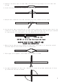
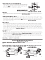
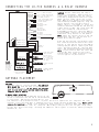
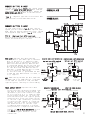
INSTALLATION GUIDE
•
OWNER’S GUIDE
REMOTE STARTER • MODELS RS202/RS202E
CONTENTS
System Features ......................................1
System Components ....................................1
Required Tools .......................................1
Technical Assistance .................................1
Before You Begin .....................................2
Precautions ..........................................2
Testing Your Wires ...................................2
Making Connections .................................2-4
Locating & Making Connections ......................4-5
Neutral Safety Switch ................................5
Connecting 18-Pin Harness ............................6
Connecting 4-Relay Harness ...........................6
Antenna Placement ....................................6
Anti-Theft System ....................................7
Optional Connections ...............................7-9
Operating Instructions ...............................9
Programming Instructions ..........................9-10
Technical Assistance
All tech personnel are expertly qualified to answer any technical questions.
Technicians are available Monday through Friday from 9:00 a.m. until 8:00 p.m. and Saturday 10:00 a.m. until 4:00 p.m.
Address
288 Canton Avenue • Wintersville, Ohio 43953
Telephone
Phone: 740-264-4710 • 800-878-8007 • Fax: 740-264-7306
SYSTEM FEATURES
Four-Button Extended Range
Remote Control
Remotely start your car to run the heater or air conditioning from an extended distance.
Keyless Entry
Remotely locks and unlocks your power door locks.
Trunk Release
Remotely opens your trunk with a push of a button. (Optional part #775 required)
Remote Programmable Run Time
Remotely program your vehicle to run 5 to 15 minutes.
Run Time Confirmation
Lets you check the run time that the unit is programmed for.
Tach/Tachless Option
A programmable feature that lets you choose from the easy to install tachless operation or
the standard wire-in, tach operation.
Parking Light Confirmation
Confirms that your vehicle has received a remote signal and will remain on if the engine is
remotely started.
Dome Light Supervision
Never walk up to a dark vehicle again. When unlocking the vehicles doors by remote control
the dome light will come on and stay on for 1 minute, or until you activates the ignition
switch. (Optional part #775 required)
Cold Start
Remotely program your car to start at a preset temperature. Automatically starts your car in
freezing temperature so you never have a dead battery.
Automatic Start
Remotely program your car to start every 3 hours regardless of temperature.
Pit Stop Mode
Allows you to exit the vehicle while the engine remains running.
Extended Range Antenna
Allows you to operate your system from up to 400 feet away. (800 feet for E Models)
Code Learning
Allows your remote starter to learn new remotes, should you want to add remotes, or if remotes
are lost.
SYSTEM COMPONENTS
Your system includes:
1-Installation & Operation Guide
1-Main Control Module
2-Four Button Remote Transmitter with Slide Protectors
1-(4) Relay Harness with Relays
1-18-Pin Wire Harness
1-Hood Pin Switch
1-Extended Range Antenna (E Model Only)
2-Window Clips (E Model Only)
1-Warranty
1-Warning Sticker for Under the Hood
2-Bulldog Window Decals
REQUIRED TOOLS
You will need a computer-friendly test light and a 5/16 drill bit when mounting the hood pin switch. In
most cases no additional tools are required, however if the bottom of your dash on the driver’s side will
come off you must remove it. In this case a screwdriver or socket set may be needed.
TECHNICAL ASSISTANCE
Should you need help. First check our website at www.bulldogsecurity.com/wires.htm or call our toll-free
Tech Support Hotline Monday through Friday 9AM-8PM and Saturday 10AM-4PM EST at 800-878-8007.
You must give the following information:
•Name
•Telephone Number with Area Code (Fax number if applicable)
•Year, Make, and Model of the vehicle
•The model number of the system you are installing
•The type of assistance you are requesting
If you give the above information you will be called back as soon as possible, usually within 10 minutes.
1
BEFORE YOU BEGIN
Congratulations, you have purchased one of the most advanced remote starter systems ever made. Your new
remote starter is a technological breakthrough utilizing the most advanced, state of the art technology
and components. It is computer controlled and manufactured in the U.S.A. The dependability and variety of
features make Bulldog Security the leader in the industry. Enjoy your new remote starter for years to
come!
This remote system is designed to start your vehicle by sending a command signal from the remote transmitter
or by programming automatic temperature or timed start. It is required that your installation is done in
a well-ventilated area. It is the responsibility of the owner to ensure that the remote system is not
used to start the vehicle in an undesired location.
It is recommended that a carbon monoxide detector be installed in the living area near a location where
the vehicle may be garaged.
Since there are many different makes and models of vehicles, look at the wiring chart on or our website,
www.bulldogsecurity.com/wires.htm.
Read this manual thoroughly before starting the installation. You must also decide if any options are
desired such as trunk release and dome light supervision. An optional relay will be needed for these
options. Please do not skip any steps.
TACH/TACHLESS OPERATION
In most cases the decision to go with tachless mode will save time during the installation. If your vehicle
is hard-starting then you should use tach mode.
MAKE SURE YOU PLACE THE WARNING STICKER UNDER THE HOOD.
PRECAUTIONS
This system is designed for vehicles with power door locks only.
This system will add remote keyless entry features to any vehicle with power door locks. This will also
work as a replacement system for the factory installed keyless entry system.
DO NOT use mechanical wiring connections, such as crimp or snap together taps. Follow instructions
on pages 2-3.
DO NOT disconnect the battery if the vehicle has an anti-theft-coded radio or is equipped with an airbag.
Doing so may cause a warning light to be displayed and may require a trip to the dealer to be corrected.
DO NOT leave the interior or exterior lights on for an extended period of time as it may cause battery
drain.
DO NOT mount the control module until all connections have been made and tested. Using wire ties or
double sided tape, MOUNT THE MODULE UNDER THE DASH.
TESTING YOUR WIRES
When testing for a positive or negative voltage, you must use a computer friendly test light (logic probe)
or a volt/ohm meter. Make sure to probe and test each wire before making your connections.
MAKING WIRING CONNECTIONS
1. Strip back two inches of insulation on the wire from the keyless entry.
Two Inches of Bare Wire
2. Strip back one inch of insulation on the wire you need to connect to.
One Inch of Bare Wire
2
3. Separate the vehicle wire as shown. Make the separation large enough to fit the other wire
through.
4. Insert the wire from the unit through the hole as shown.
5. Wrap the wire around one side then the other and finally around itself as shown.
1
2
3
6. Use electrical tape to wrap. Be sure to cover the wire about two inches on either side of the
connection. First pull the wire that you have just connected along side the wire you connected
to, tape and wire tie them together. Use this method for all connections.
Wire Tie
Electrical Tape
CAUTION: All wires must be wrapped and taped.
MAKING END TO END CONNECTIONS
FOLLOW THESE INSTRUCTIONS
1. When tying two separate wires together at their ends, strip back 1” of insulation on both
wires and separate the strands of wire as shown below.
2. Twist upper wires together, twist lower wires together as shown.
3. Lay upper twisted pair of wires over right wire as shown. Bring lower twisted pair of wires
up to meet the left wire as shown.
3
4. Use electrical tape to wrap, be sure to cover about 2 inches on either side of connection.
Secure with wire ties as shown.
Electrical Tape
Wire Tie
Wire Tie
Use this method ONLY when connecting two separate wires end to end.
LOCATING & MAKING CONNECTIONS
Please see the wiring chart on our website, www.bulldogsecurity.com.
CONSTANT POWER (+12V, key in any position including off)
These wire(s) are in your vehicle’s main ignition harness, usually located on the steering column coming
from the ignition switch. Probe each wire with your test light. The correct wire(s) will show +12V when
the ignition switch is in these 5 positions (ACC-LOCK-OFF-RUN-CRANK).
1. If your vehicle has only (1) constant power wire, attach the
IGNITION HARNESS
RED wire from the 18-pin harness and both large RED wires from
UNDER DASH
the 4-relay harness to the constant power wire in the vehicle.
2. If your vehicle has (2) constant power wires, attach the RED
wire from the 18-pin harness and (1) large RED wire from the
4-relay harness to one of these constant power wires. Then
connect the other large RED wire from the 4-relay harness to the
second constant power wire in the vehicle.
Make sure to wrap electrical tape around all (3) fuse holders to prevent shorting to ground.
IGNITION WIRE(S) (+12V in run and crank position only)
The ignition wire(s) are also located in the main harness coming from the ignition switch. Probe each
wire with your test light, the correct wire(s) will show +12V only when the ignition switch is in the
RUN AND CRANK positions only. The correct wires will not show +12V when in the OFF or ACCESSORY position.
Most Ford, GM, and Chrysler vehicles have at least (2) ignition wires. Most foreign vehicles have only
(1).
1. Strip back the YELLOW wire from the 18-pin harness and then strip back (1) of the (2) WHITE wires
from the 4-relay harness and twist both of these wires together.
2. Connect the YELLOW wire and the WHITE wire from step (1) to the ignition wire in the main harness.
If your vehicle has only (1) ignition wire, tape off the end of the second WHITE wire from the 4relay harness and do not use.
3. If your vehicle has (2) ignition wires, connect the second WHITE wire from the 4-relay harness to
it.
4. If your vehicle has (3) ignition wires (some GMs) connect the second WHITE wire from the 4-relay
harness to both the second and third ignition wires in the vehicle.
HEATER/BLOWER MOTOR WIRE(S) (+12V in run position only)
Most vehicles will have (1) blower wire; however some Fords, newer GM vehicles and Chrysler 94 and up
will have (2) or more blower wires. To locate these wire(s) probe for wire(s) that only show +12V when
the ignition switch is in the RUN position only. This wire(s) will not show +12V when the ignition switch
is in any other position.
1.If your vehicle has only (1) blower wire connect the WHITE WITH BLACK STRIPE wire from the 4-relay
harness to this wire.
2.If your vehicle has (2) blower wires, connect the WHITE WITH BLACK STRIPE wire to both.
3.If your vehicle has (3) blower wires connect the unused WHITE wire from the 4-relay harness to the
third blower wire.
STARTER/CRANK WIRE (+12V only in the start position only)
The starter/crank wire is also in the main harness. Locate the wire that shows +12V only in the crank
position. This wire will not show +12V in any other position. Attach the YELLOW WITH BLACK STRIPE wire
from the 4-relay harness to this wire.
CHASSIS GROUND
Factory Bolt
Locate an easy to get to bolt or screw
located under the driver’s side of the dash and
attach the BLACK ground wire from the 18-pin
Spade Connector
harness securely as pictured.
Black Ground Wire
Note: Remove any paint below
the spade connector.
4
PARKING LIGHTS (+12V only with parking lights on)
Turn the parking lights to the ON position. (NOT YOUR HEADLAMPS).
Probe the wire(s) coming from your headlamp control switch. Find
a wire that will show +12V only when the parking lights are ON.
Connect the BROWN wire from the 18-pin harness to this wire. If
this wire tests as a (-) negative, see diagram.
YELLOW
WHITE
RED
BLACK
87a
Brown wire
from 18 pin
harness
NEGATIVE PARKING LIGHT OUTPUT
Optional part #775 required.
To (-)Parking
Light Output
BLUE
To Ground
To Ground
DO NOT USE THE RED WIRE, TAPE OFF.
BRAKE INPUT
The brake wire is located on the switch near and above the brake pedal. The correct wire will show
+12V only when the brake is pressed. Connect the BLUE WITH BLACK STRIPE from the 18-pin harness to this
wire.
FACTORY ALARM SHUT DOWN WIRE (FASD) (-)
If your vehicle is equipped with a factory alarm system (as most vehicles with a factory keyless entry
are) probe for a small gauge wire (usually found in the driver’s side kick panel) that shows (-) ground
when the door lock cylinder is turned to the unlock position using the key. This wire will usually show
a (+) positive voltage before turning the key. NOTE: Some factory disarm wires remain neutral before
you turn the key to unlock instead of +12v positive. Connect the RED WITH BLACK STRIPE wire from the
18-pin harness to this wire.
HOOD PIN SWITCH
This feature will keep the engine from starting or shut off the engine when the hood is opened.
Locate a good chassis ground, if at all possible do not install the pin switch in the rain gutter.
Drill a 5/16 hole, insert the pin switch into the hole and tighten. Check for the hood adjustment,
there is approximately 1/4” adjustment in the pin switch. Close the hood easy, making sure that
the pin switch is not keeping the hood from closing all the way, if it does, cut off approximately
1/8” of the black plastic off of the top of the hoodpin switch and try closing the hood again.
Check to make sure that the hoodpin switch remains neutral when the hood is closed and shows ground
when the hood is open. Plug the BLACK WITH BLUE STRIPE wire from the 18-pin harness into the bottom
of the hood pin switch.
TACH INPUT (Optional)
By this time, you should have determined the way you want your vehicle to start (tach or tachless).
If you have chosen the TACHLESS start option, simply proceed to the next step and skip the following
connection instructions. Make sure to tape the BLACK WITH WHITE STRIPE wire up if not used. For
TACH mode connect the BLACK WITH WHITE STRIPE wire from the 18-pin harness to the negative side
of the coil or the tach wire at the coil pack under the hood. To find the coil pack follow the
spark plug wires back to the termination point. To operate in tach mode, make sure to program tach
option, see programming tach option page 10.
NEUTRAL SAFETY SWITCH
PRE-1996 GM REAR WHEEL DRIVES WITH PURPLE CRANK WIRE
Optional part #775 required.
MECHANICAL NEUTRAL SAFETY SWITCH (Rear Wheel Drive Only)
When installing a Bulldog remote starter on GM vehicles or Dodge Dakotas built prior to 1996, you
must:
Use the diagram below to create a circuit that will prevent the remote starter from starting the
vehicle unless the key is removed from the ignition switch.
YELLOW
Driver’s Door Switch
TAN
Ground
Key
Cylinder
GREEN
PRE-1996 DODGE DAKOTAS
Optional part #775 required.
Ground
Tie into
heavy white
wire on
4-relay
harness
WHITE
86
87
85
87a
5 Amp
fuse
YELLOW
Driver’s Door Switch
BLACK
BLACK/LT.BLUE
Ground
30
BLUE
(-) Negative
hood pin wire
RED
NOT USED,
TAPE OFF
Key
Cylinder
LT.BLUE/GREEN
Message
center or
key buzzer
Tie into
heavy white
wire on
4-relay
harness
WHITE
86
87
85
87a
5 Amp
fuse
Ground
BLACK
30
BLUE
RED
NOT USED,
TAPE OFF
(-) Negative
hood pin wire
Message
center or
key buzzer
5
CONNECTING THE 18-PIN HARNESS & 4-RELAY HARNESS
BROWN/BLACK
GREEN/BLACK
BLACK/WHITE
BLACK/BLUE
BLUE
VIOLET
WHITE/RED
ORANGE
BROWN
GRAY
GRAY/BLACK
YELLOW
BLUE/BLACK
BLACK/YELLOW
GREEN
RED/BLACK
BLACK
RED
(+) or (-) Door Lock pulse
(-) or (+) Door Unlock pulse
Tach (-) to neg. side of coil
(-) To hood pin switch
(-) Aux. alarm channel input
(-) Dome light supervision
(-) Trunk release
(not used)
(+) Parking lights
(not used)
(not used)
Ignition input
(+) Brake switch
(not used)
(not used)
(-) Factory alarm shutdown
Ground
To +12V constant
WHT/BLK 16 ga.
WHITE 16 ga.
YEL/BLK 16 ga.
750ma (-)
Outputs
RED
RED
YELLOW
ANTENNA
Keep as
straight as
possible,
tape end
to hold
straight.
2 Red wires need
+12V constant.
Either white
wire to Ignition
1. If your car
has 2 ignitions
use both.
For Passlock I
WHT/BLK 16 ga
WHITE
For Passlock II
WHITE 16 ga
YELLOW/BLACK
To Starter/Crank
Wire
WHITE/BLACK
To Heater/Blower
Motor Wire
For Passlock I
YEL/BLK 16 ga
WHITE
Tap here when
installing bypass
module 721.
CAUTION: Before connecting the 18-pin
harness to the module, double check all
connections to be sure they are secure
and properly wrapped with electrical tape.
Mount the unit under the driver’s side
dash. Make sure to properly place antenna.
(See antenna placement page 15.) Plug the
18-pin harness into the main control
module. Once it is plugged in, press and
release transmitter button #4, the parking
lights flash 3 times. The flash confirms
that the transmitter code has been
programmed to the unit. Once the module
is programmed, connect the 3-pin harness
from the 4-relay harness to the module.
NOTE: There are several wires in the 18pin harness that will not be used. All
unused wires must be taped.
Press the start button, the parking lights
will flash once and the vehicle will start
and run. If your vehicle starts and remains
running and you wish to connect your door
locks, proceed to page 16, “Testing Door
Locks”, and follow the provided instructions.
NOTE: If your vehicle does not start and
run you may have a factory anti-theft
system. Refer to pages 15 and 21 to see
if this applies to your vehicle.
ANTENNA PLACEMENT
ANTENNA
For best results, run the antenna (YELLOW WIRE
WITH BLACK TIP from the back of the unit) as
straight as possible. Do not place the antenna
next to any metal parts or the vehicle’s main
computer control module. Range is up to 400 feet.
Antenna Wire
Antenna Tube
E MODEL REMOTE STARTERS
Run the antenna up the windshield pillar on the
driver’s side and across the top of the windshield Control Module
to the center, behind the rearview mirror. Use
the antenna clips provided to hold it in place. Be sure to expose the full length of the clear
antenna. It will perform best if mounted vertically, below the dark windshield tint. Never leave
antenna in headliner. Range is up to 800 feet. Each receiver is tested to more than 400 feet
(800 feet, E models) of clear air reception. While many times you will see a higher range. Many
factors will affect the range, including the amount of radio signals in the area, battery strength,
window tint, etc.
6
FACTORY ANTI-THEFT SYSTEMS
FOR GENERAL MOTORS CARS ONLY
System 1: PASSKEY I and II system (1985 and up). This system has a resistor pill in the key. Measure
resistance of the pill using a test meter. A bypass module is available, part #VATS-WR module.
System 2: PASSLOCK I and II system (1995 and up). Passlock does not have a pill in the key. It has a
light on the dash that states ANTITHEFT OR SECURITY system. A bypass module is available, part #GMBP721 module.
System 3: PASSKEY III system (GM 1998 and up). Passkey III is GMs version of a transponder system. This
key will have the letters PK3 on it. A bypass module is available. (Part #781)
FORD ANTI-THEFT SYSTEM: PATS
Ford uses a bypass part #FBP-718 module, 1995-1998. (1999 and up will use part #781.)
CHRYSLER AND MOST IMPORTS ANTI-THEFT SYSTEM: TRANSPONDER
1998 and up will use part #781.
To order these bypass modules call 1-800-878-8007.
OPTIONAL CONNECTIONS
TESTING: Door Locks
There are three basic types:
“Type A” Door Lock Test (Most GMs and some Chryslers)
Probe both of your door lock wires going to the door lock switch usally located in the driver’s kick
panel. Attach the clip end of your test light to a good chassis ground. Using the vehicle’s door lock
controls, activate the lock then the unlock, testing both wires one at a time. If one of these wires
tests (+) positive when lock is pressed and the other tests (+) positive when they are unlocked, your
vehicle has a “Type A” door locking system. Make sure to mark which wire is lock and unlock. Proceed
to Connecting Door Locks, Connecting Door Locks. NOTE: “Type A” and “Type C” locks will test the same,
until you test for ground. Make sure you run both tests before making your connections.
“Type B” Door Lock Test (Most Imports, some newer Fords)
Probe both of your door lock wires going to the door lock switch usally located in the driver’s kick
panel. Attach the clip end of your test light to +12V. Using the vehicle’s door lock controls, activate
the lock then the unlock testing both wires one at a time. If the test light illuminates when you probe
the lock and the unlock wires your vehicle has a “Type B” door locking system. Make sure to mark which
wire is lock and unlock. Proceed to Connecting Door Locks.
“Type C” Door Lock Test (Most Fords, some Chryslers, GM Trucks)
(Optional part #778 required)
Using your test light probe both the lock and the unlock wires usually located in the driver’s kick
panel. Attach the clip end of your test light to ground probing both wires one at a time while locking
and unlocking the doors with the driver’s side switch (usually the master switch). The test light should
illuminate in both switch positions. Now attach the clip end of your test light to +12V constant, probe
both wires one at a time again. The light should then illuminate again only in reverse order. This
tells you that you have a “Type C” reversing polarity system. Make sure to mark which wire is lock and
unlock. Proceed to Connecting Door Locks.
CONNECTING DOOR LOCKS
(Optional)
CONNECTING “TYPE A LOCKS”
•If your vehicle has a “Type A” door locking system,
connect the BROWN WITH BLACK STRIPE wire from the
18-pin harness to the door lock wire. Connect the
GREEN WITH BLACK STRIPE wire to the unlock wire.
See diagram below.
“Type A” - Positive type door locks used on most
GM, some Chrysler vehicles.
BROWN/BLACK
LOCK
UNLOCK
GREEN/BLACK
7
CONNECTING “TYPE B LOCKS”
• If your vehicle has a “Type B” door locking system,
connect the GREEN WITH BLACK STRIPE wire from the
18-pin harness to the door lock wire. Connect the
BROWN WITH BLACK STRIPE wire to the unlock wire.
See diagram below.
LOCK
GREEN/BLACK
UNLOCK
“Type B” - Negative type door locks used on most
imported vehicles and some newer Fords.
BROWN/BLACK
YELLOW
CONNECTING “TYPE C LOCKS”
•If your vehicle has a “Type C” door locking
system, you will need to purchase optional part
#778. Once you have purchased the relays, follow
the diagram on page 18 for “Type C” door locks.
BLACK
NOTE: When testing the door pin wire, make sure
the dome light is on. Some vehicles, if the door
is left open for a period of time, the dome
light will go out, resulting in a false reading.
TRUNK RELEASE OUTPUT (Optional Part #775
required)
Locate the trunk release wire coming from
the back of the trunk release switch. To
determine if your trunk release is tripped
by a (+) positive or a (-) negative (most
trunk release switches are (+) positive).
Place one end of your test light to ground,
probe the wire. Press the “Trunk” button,
if the test light illuminates, you have a
(+) positive trunk release. If it does not,
connect the test light to +12V constant
and probe the wire. If the test light
illuminates when the button is pressed,
then you have a (-) negative trunk release.
Connect the WHITE WITH RED STRIPE wire to
the WHITE wire of the optional relay.
Please use figures below for correct
connections.
RED
BLUE
TYPE C - (Optional Part #778 required)
Reverse polarity door locks. Used on most GM
trucks, Ford and Chrysler vehicles.
DOME LIGHT (Optional Part #775 required)
To determine if your dome light is turned on
with (+) positive or (-) negative trigger,
probe for a wire in the driver’s side kick
panel that switches polarity when the door
is closed then opened. You can also find this
wire going to the under dash courtesy lights.
•If this wire reads +12V when the door is
open and (-) ground when the door is closed,
it is (+) positive. (most Fords)
•If this wire reads (-) ground when the door
is open and +12V when the door is closed, it
is (-) negative.
WHITE
87a
BLACK
RED
BLUE
NEGATIVE DOME LIGHT SUPERVISION
POSiTIVE DOME LIGHT SUPERVISION
Optional part #775 required.
Optional part #775 required.
YELLOW
WHITE
(-) VIOLET
FROM 18-pin
wire
harness.
RED
To Dome Light
Circuit
BLACK
87a
+12 VOLT
FUSED AT
5 AMPS
YELLOW
WHITE
(-) VIOLET
FROM 18-pin
wire
harness.
BLUE
To Dome Light
Circuit
BLUE
RED
DO NOT USE,
TAPE OFF.
DO NOT USE,
TAPE OFF.
Ground
NEGATIVE TRUNK RELEASE
BLACK
87a
+12 VOLT FUSED
AT 20 AMPS
POSITIVE TRUNK RELEASE
Optional part #775 required.
TO FACTORY TRUNK WIRE
TO FACTORY TRUNK WIRE
YELLOW
WHITE
WHITE/RED
FROM ALARM
RED
87a
YELLOW
BLACK
WHITE
WHITE/RED
FROM ALARM
BLUE
BLUE
RED
+12 VOLT FUSED
AT 10 AMPS
BLACK
87a
+12 VOLT FUSED
AT 20 AMPS
THE RED WIRE IS NOT USED, TAPE OFF.
8
AUXILIARY INPUT
If you wish to use this starter with an aftermarket alarm, connect the BLUE wire from the 18-pin
harness to the second or third channel (-) output of your existing alarm. When the output is
activated, a (-) signal will be supplied to the remote starter.
OPERATING INSTRUCTIONS
Start
BUTTON #1
Starts your vehicle from 400 feet
away. (E-Model, up to 800 feet)
Loc k
Unlock
BUTTON #2
Locks and unlocks your power door
locks.
Trunk
BUTTON #3
Pops your trunk
Stop
BUTTON #4
Shuts engine off and programs runtime.
BULLDOG
1. Starting the Vehicle with the Remote Transmitter
Press and release button #1 (start). The parking
lights will flash once, confirming the car starter
received the signal. The car will then start and
the parking lights will turn on and remain on while
the vehicle is running. To shut off the engine
before the preset time, press button #4 (stop) or
press the brake pedal. NOTE: If your car does not
start on the first crank it will automatically
attempt to start up to 2 more times. (only in
tachless mode) In tachless mode, parking lights
will wait approximately 10 seconds before turning
on.
2. Pit Stop: Exiting the Car with the Engine Running
Make sure the transmission is in park and press button #1 (start) before turning the ignition switch off.
(The engine will remain running for the preset time.)
3. Keyless Entry Operation
Press button #2 (lock/unlock), the parking lights will flash once and the doors will lock. Press button #2
again, the parking lights will flash twice, the doors will unlock, and the parking lights will remain on for
one minute or until you turn the ignition on or press the brake.
4. Dome Light Option
The remote starter includes an optional output that can be used to illuminate the dome light when pressing
button #2 and unlocking your power door locks. The dome light will remain on for one minute or until you
turn the ignition on or press the brake.
5. Trunk Release Output
The remote car starter includes an optional output that can be used to do one of the following: open the
trunk (optional part #775 required), roll up the windows (optional module part #WRU-B), close the sun roof
(optional part #775 required) etc. This output will pulse .75 seconds when pressed and released. In instances
where a continuous signal is needed such as sun roof and power windows, hold down button #3 (trunk) as long
as the signal is needed to complete the task. The parking lights will remain on as long as this button is
being pressed.
6. Runtime Confirmation (Engine Not Running)
To check programmed runtime, press and release button #4 (stop), the parking lights will flash for the programmed
length of time. Each flash will equal 5 minutes of runtime.
PROGRAMMING INSTRUCTIONS
ENTERING PROGRAMMING MODE
Make sure your vehicle is not running and the brake is pressed. The brake is to remain pressed as long as you want
to remain in programming mode. The only exception is when a different remote has been learned. The unit will exit
the programming mode simply by releasing the brake and the parking lights will flash three (3) times.
Adding Additional Remotes
Press and hold brake. Next, press and hold Button #1 on the working remote until the parking lights flash once. Release.
Press and release Button #4 on the new remote. The parking lights will flash three (3) times confirming that the new
remote was learned.
Automatic Start - Off
Press and hold brake. Press and hold Button #2 until the parking lights flash twice. Release. Press and release Button
#1. The parking lights will flash twice. The automatic start is programmed OFF. Release the brake, the parking lights
will flash three (3) times. NOTE: Factory setting is OFF.
9
Cold Start On and Off (Degree Select)
Press and hold brake. Press and hold Button #2 until the parking lights flash twice. Release. Press and hold Button
#2. Each parking light flash is a progression in degrees. Flash #1 is -40ºF, flash #2 is -30ºF, flash #3 is -20ºF,
flash #4 is -10ºF, flash #5 is 0ºF, flash #6 is +10ºF, flash #7 is +20ºF. Two quick flash parking light flashes is
Cold Start Off. Release the brake, the parking lights will flash three (3) times. NOTE: Factory setting is OFF.
Door Lock Pulse Length (Long)
Press and hold brake. Next, press and hold Button #3, the parking lights will flash three (3) times. Release. Press and
release Button #1. The parking lights will flash once, the door lock pulse length will be 3.5 seconds of output. Release
the brake, the parking lights will flash three (3) times. (For European type door locks)
Door Lock Pulse Length (Short)
Press and hold brake. Next, press and hold Button #3, the parking lights will flash three (3) times. Release. Press and
release Button #1. The parking lights will flash twice, the door lock pulse length will be 0.7 seconds of output. Release
the brake, the parking lights will flash three (3) times. NOTE: Factory setting is SHORT pulse length.
Tach Mode - ON
Press and hold brake. Press and hold Button #3, the parking lights will flash three (3) times. Release. Press and release
Button #4, the parking lights will flash twice. The Tach Start is programmed ON. Release the brake, the parking lights
will flash three (3) times.
Tachless Mode - ON
Press and hold brake. Press and hold Button #3, the parking lights will flash three (3) times. Release. Press and release
Button #4, the parking lights will flash once. The Tachless Start is programmed ON. NOTE: Factory setting is Tachless Start
ON. Release the brake, the parking lights will flash three (3) times.
Programming Runtime with Brake not Pressed
Press and hold Button #4. The parking lights will flash once for every five (5) minutes you want to program. Release button
at desired runtime. Maximum length, 15 minutes.
10