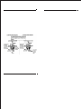
1
Creating A
Higher Standard
JBS Technologies
produces the world's
most innovative and
reliable car alarms,
remote starters,
keyless entry systems
and starter
immobilizers.
JBS Technologies is not
an importing or
distribution company.
Our products are
designed with patented
technology and
produced in the United
States with robotics to
insure flawless
performance and the
highest quality control.
INSTALLATION GUIDE
•
OWNER'S GUIDE
Look for our products
and services on the
world wide web where
you'll find a highly
trained support staff to
provide assistance to
get you on your way to
a safer, more
convenient driving
experience.
JBS Technologies
225 Technology Way
Steubenville, OH 43952
Phone: 740-282-1212
Toll Free: 800-878-8007
Fax: 740-282-1201
www.jbstech.com
JBS TECHNOLOGIES
Creating A Higher Standard
YOUR WARRANTY
Thank you for purchasing American made
products by JBS Technologies.
To order additional transmitters or other
accessories, visit our
website at wwww.jbstech.com or contact
JBS Technologies at
the following address:
JBS Technologies
225 Technology Way
Steubenville, OH 43952
FOR TECHNICAL ASSISTANCE
Here's how your warranty works:
JBS Technologies warrants to the original customer,
and the original car a limited lifetime warranty.
Within 12 months of purchase, JBS Technologies will
repair or replace, our option, any defective system at
no charge. After 12 months from date of purchase,
JBS Technologies will, at our option, repair or replace
the system for a $20 shipping and handling fee.
Installation, labor, removal and reinstallation are not
the responsibility of JBS Technologies. Registration
must be completed and sent in within seven (7) days
of purchase in order to validate the warranty. JBS
Technologies makes no warranty against the theft of
a vehicle or its contents. This warranty is not to be
construed as an insurance policy against loss.
www.jbstech.com
1-800-878-8007
TO ORDER ACCESSORIES, CALL
1-800-659-0764
DISCLAIMER
JBS Technologies disclaims the warranty of
merchantability and fitness for any particular use. This
disclaimer shall be effective as to all claims of any
kind made by or through any wholesaler, retailer,
consumer or any other person or entity. Some states
do not permit the disclaimer of implied warranties in
some sales. Hence, this disclaimer may not apply to
you.
LIMITATION OF REMEDIES
Consumer's remedy is limited to repair or replacement
of the unit, and in no event shall exceed the purchase
price. Incidental, consequential an/or indirect damages
are expressly disclaimed. NO person or entity is
authorized to alter, amend or increase this limited
warranty.
WARRANTY VALIDATION
CONTENTS
PLEASE FILL OUT THIS FORM
AND MAIL IT IN TO REGISTER YOUR WARRANTY
System Features ..........................
4
Your Name ________________________________________
System Components........................
5
Address ________________________________________
Required Tools ...........................
5
________________________________________
Technical Assistance ....................
5
5-6
Dealer Name ____________________________________
Precautions ..............................
6
Address ________________________________________
Testing Your Wires.......................
7
________________________________________
Date of Purchase ___/___/___ Model # __________
Make/Model of Car ______________________________
Year of Car _____
V.I.N. # ____________________
Final Quality Check By _________________________
Mail to: JBS Technologies
225 Technology Way • Steubenville, OH 43952
PROGRAMMING FUNCTIONS
FOR YOUR WALLET OR GLOVE BOX
ATTENTION:
We urge you to immediately place this card in your wallet.
Adding Additional Remotes Press and hold brake. Next, press and hold Button
#1 on the working remote until the parking lights flash once. Release.
Press and release Button #4 on the new remote. The parking lights will
flash three (3) times confirming that the new remote was learned. Cold
Start On and Off (Degree Select) Press and hold brake. Press and hold
Button #2 until the parking lights flash twice. Release. Press and hold
Button #2. Each parking light flash is a progression in degrees. Flash
#1 is -40ºF, flash #2 is -30ºF, flash #3 is -20ºF, flash #4 is -10ºF, flash
#5 is 0ºF, flash #6 is +10ºF, flash #7 is +20ºF. Two quick parking light
flashes is Cold Start Off. Release the brake, the parking lights will flash
three (3) times. NOTE: Factory setting is OFF. Tach Mode - ON
Press and hold brake. Press and hold Button #3, the parking lights will flash
three (3) times. Release. Press and release Button #4, the parking lights
will flash twice. The Tach Start is programmed ON. Release the brake, the
parking lights will flash three (3) times. Tachless Mode - ON Press and
hold brake. Press and hold Button #3, the parking lights will flash three
(3) times. Release. Press and release Button #4, the parking lights will flash
once. The Tachless Start is programmed ON. NOTE: Factory setting is Tachless
Start ON. Release the brake, the parking lights will flash three (3)
times.Programming Runtime with Brake not Pressed Press and hold Button #4.
The parking lights will flash once for every five (5) minutes you want to
program. Release button at desired runtime. Maximum length, 15 minutes.
26
Making Connections ....................
Locating & Making Connections .......
7-8
9-11
Neutral Safety Switch ..................
12
Connecting 18-Pin Harness..............
13
Connecting 4-Relay Harness.............
13
Antenna Placement.......................
14
Anti-Theft System.......................
14
Optional Connections ................
15-18
Operator Programming Instructions..
18-19
How to use Your Remote Transmitter ....
Vehicle Anti-Theft Chart............
FCC ID Notice ...........................
Important Functions .................
20
21-24
24
25-26
Warranty Validation ....................
26
Your Warranty ...........................
27
Protected by one or more
of the following patents:
Patent #08528768
Patent
Patent #55459447
Patent
Patent #60087174
Patent
Patent #5886622
Patent
Other patents pending.
RS700
Before You Begin.......................
#5477090
#5677664
#60097821
#5942988
3
REMOTE CONTROL STARTER
Email Address _________________________________
SYSTEM FEATURES
Four-Button
Extended Range
Remote Control
Remotely start your car to run the heater or air
conditioning from an extended distance.
Keyless Entry
Remotely locks and unlocks your power door locks.
Trunk Release
Remotely opens your trunk with a push of a
button. (Optional part #775 required)
Remote Programmable
Run Time
Remotely program your vehicle to run 5 to 15
minutes.
Run Time
Confirmation
Lets you check the run time that the unit is
programmed for.
Tach/Tachless
Option
A programmable feature that lets you choose from the
easy to install tachless operation or the standard
wire-in, tach operation.
Parking Light
Confirmation
Confirms that your vehicle has received a remote
signal and will remain on if the engine is remotely
started.
Dome Light
Supervision
come
Never walk up to a dark vehicle again. When unlocking
the vehicles doors by remote control the dome light
will
on and stay on for 1 minute, or until you activate the ignition
switch. (Optional part #775 required)
Cold Start
Remotely program your car to start at a preset
temperature. Automatically starts your car in freezing
temperature so you never have a dead battery.
Pit Stop Mode
Allows you to exit the vehicle while the engine
remains running.
Extended Range
Antenna
Allows you to operate your system from up to 400 feet
away. (800 feet for E Models)
Code Learning
Allows your remote starter to learn new remotes,
should you want to add remotes, or if remotes are lost.
Limited Lifetime
Warranty
Guarantees life-long protection.
4
1-800-878-8007
www.jbstech.com
MADE IN AMERICA, GUARANTEED FOREVER
OPERATING FUNCTIONS
FOR YOUR WALLET OR GLOVE BOX
ATTENTION:
We urge you to immediately place this card in your wallet.
Starting with the Remote Transmitter Press and release button #1. The parking lights
will flash once, confirming the car starter received the signal. The car will then start
and the parking lights will remain on while the vehicle is running. To shut off the
engine before the preset time, press button #4 or press the brake pedal. NOTE: If your
car does not start on the first crank it will automatically attempt to start 2 more
times (in tachless mode). While in tachless mode, parking lights will wait approximately
10 seconds before turning on. Pit Stop: Exiting the Car with the Engine Running Make
sure the transmission is in park and press button #1 before turning the ignition switch
off. Keyless Entry Operation Press button #2, the parking lights will flash once and
the doors will lock. Press button #2 again, the parking lights will flash twice, the
doors will unlock, and the parking lights will remain on for one minute or until you
turn the ignition on or press the brake. Dome Light Option (optional) The dome light
will remain on for one minute or until you turn the ignition on or press the brake.
Trunk Release Output Optional output modules are available to do one of the following:
open the trunk, roll up the windows, close the sun roof etc. This output will pulse
.75 seconds when pressed and released. In instances where a continuous signal is needed
such as sun roof and power windows, hold down button #3 as long as the signal is needed.
The parking lights will remain on as long as this button is being pressed. Runtime
Confirmation Press and release Button #4. The parking lights will begin to flash. Each flash equals
5 mnutes of runtime.
25
VEHICLES WITH FACTORY
ANTI-THEFT SYSTEMS (CONT.)
Manufacturer
PONITAC
PORSCHE
SAAB
SATURN
TOYOTA
VOLKSWAGON
VOLVO
Make/ Year
BONNIEVILLE 89+
FIREBIRD 88+
GRAND AM 96-98
GRAND AM 99+
GRAND PRIX 92-96
MONTANA 99+
SUNFIRE 96-99
SUNFIRE 2000+
ALL 97+
ALL 97+
ALL 97+
2000+
AVALON 98+
CAMRY 98+
LAND CRUISER 98+
SOLARIA 99+
SUPRA 98+
BEETLE 98+
GOLF 98+
PASSAT 98+
ALL 98+
Anti-theft
VATS
VATS
PASSLOCK 1
PASSLOCK 2
VATS
TRANSPONDER
PASSLOCK 1
PASSLOCK 2
TRANSPONDER
TRANSPONDER
FACTORY
TRANSPONDER
TRANSPONDER
TRANSPONDER
TRANSPONDER
TRANSPONDER
TRANSPONDER
TRANSPONDER
TRANSPONDER
TRANSPONDER
TRANSPONDER
SYSTEM COMPONENTS
Your system includes:
1-Installation & Operation Guide
1-Main Control Module
1-Four Button Remote Transmitter
with Slide Protector
1-(4) Relay Harness with Relays
1-18-Pin Wire Harness
1-Hood Pin Switch
1-Extended Range Antenna (E Models Only)
2-Window Clips
(E Models Only)
1-Warranty
1-Warning Sticker
for Under the Hood
2-Bulldog Window Decals
REQUIRED TOOLS
You will need a computer-friendly test light
drill bit when mounting the hood pin switch.
no additional tools are required, however if
your dash on the driver’s side will come off
it. In this case a screwdriver or socket set
and a 5/16 inch
In most cases
the bottom of
you must remove
may be needed.
TECHNICAL ASSISTANCE
Should you need help. First check our website at www.jbstech.com or call
our toll-free Tech Support Hotline Monday through Friday 9AM-8PM and
Saturday 10AM-4PM EST at 800-878-8007.
You must give the following information:
• Name
• Telephone Number with Area Code (Fax number if applicable)
• Year, Make, and Model of the vehicle
• The model number of the system you are installing
• The type of assistance you are requesting
If you give the above information you will be called back as soon as
possible, usually within 10 minutes.
BEFORE YOU BEGIN
FCC ID: J3STXJS1194
This device complies with part 15 of the FCC Rules,
Operation is subject to the following two conditions:
(1) This device may not cause harmful interference, and
(2) This device must accept any interference received,
including interference that may cause undesired operation.
24
Congratulations, you have purchased one of the most advanced
remote starter systems ever made. Your new remote starter is
a technological breakthrough utilizing the most advanced, stateof-the-art technology and components. It is computer controlled
and manufactured in the U.S.A. The dependability and variety
of features make Bulldog Security the leader in the industry.
Enjoy your new remote starter for years to come!
This remote system is designed to start your vehicle by sending
a command signal from the remote transmitter or by programming
automatic temperature or timed start. It is required that your
installation be done in a well-ventilated area. It is the
responsibility of the owner to ensure that the remote system
is not used to start the vehicle in an undesired location.
5
BEFORE YOU BEGIN cont.
It is recommended that a carbon monoxide detector be installed
in the living area near the location where the vehicle may be
garaged.
VEHICLES WITH FACTORY
ANTI-THEFT SYSTEMS (CONT.)
Manufacturer
Since there are many different makes and models of vehicles,
look at the wiring chart on our website, www.jbstech.com.
Read this manual thoroughly before starting the installation.
You must also decide if any options are desired such as trunk
release and dome light supervision. An optional relay will be
needed for these options. Please do not skip any steps.
TACH/TACHLESS OPERATION
In most cases the decision to go with tachless mode will save
time during the installation. If your vehicle is hard-starting
then you should use tach mode.
HONDA
MAKE SURE YOU PLACE THE WARNING STICKER UNDER THE HOOD.
INIFINITY
PRECAUTIONS
This system is designed for use with vehicle equipped with fuelinjected, gasoline engines having automatic transmissions only.
SAFETY FIRST!
Never remotely start your vehicle indoors, with the keys in the
ignition or unless the transmission is in park. A periodic safety
check is recommended to ensure that your system is in proper working
order.
DO NOT use mechanical wiring connections, such as crimp or snap
together taps. Follow instructions on page 7-8.
DO NOT disconnect the battery if the vehicle has an anti-theft-coded
radio or is equipped with an airbag. Doing so may cause a warning
light to be displayed and may require a trip to the dealer to be
corrected.
DO NOT leave the interior or exterior lights on for an extended period
of time as it may cause battery drain. Remove the dome light fuse
from the vehicle’s fuse box. NOTE: Starter systems do not work well
with a partially discharged battery.
JAGUAR
JEEP
WRANGLER 99+
LEXUS
LINCOLN
LINCOLN
MERCEDES
MERCURY
DO NOT mount the control module until all connections have been
made and tested. Use wire ties or double sided tape. MOUNT THE
MODULE UNDER THE DRIVER’S DASH.
PLEASE USE CAUTION: DO NOT CUT, PROBE OR DISCONNECT THE VEHICLE’S AIRBAG WIRES. THESE WIRES
WILL ALMOST ALWAYS BE INSIDE A BRIGHT YELLOW
TUBE LOCATED NEAR THE STEERING COLUMN HARNESS.
WARNING!
GENERAL MOTORS REAR WHEEL DRIVE VEHICLES AND DODGE DAKOTAS
All General Motors rear wheel drive vehicles and Dodge Dakotas
built prior to 1996 do not have an electrical neutral safety
switch. They have a mechanical neutral safety switch. The mechanical
neutral safety switch operates as follows.
a) The key will only turn to the start position when the
gear selector is in park or neutral.
b) The key can only be removed from the ignition switch
when the gear selector is in the park position.
You must use special precautions with this system. For more
6 information see page 12.
Make/ Year
SIERRA 98+
SONOMA 98+
SUBURBAN 98+
YUKON 98+
YUKON XL 2000+
ACCORD 98+
ODYSSEY 98+
PRELUDE 98+
S2000
I30 98+
Q45 98+
QX4 98+
ALL 98+
GRAND CHEROKEE 99+
ALL 97+
CONTINENTAL 97+
LS 2000+
MARK V3 97+
NAVIGATOR 97+
TOWN CAR 97+
ALL 97+
COUGAR 99+
MOUNTAINEER 98+
MYSTIQUE 97+
NISSAN
OLDSMOBILE
SABLE 96+
MAXIMA 98+
ACHIEVA 95+
ALERO 99+
AURORA 95+
BRAVADA 98+
CUTLASS 97+
NINETY-EIGHT
SILHOUETTE 99+
Anti-theft
PASSLOCK 2
PASSLOCK 2
PASSLOCK 2
PASSLOCK 2
PASSLOCK 2
TRANSPONDER
TRANSPONDER
TRANSPONDER
TRANSPONDER
TRANSPONDER
TRANSPONDER
TRANSPONDER
TRANSPONDER
TRANSPONDER
(GREY KEY ONLY)
TRANSPONDER
(GREY KEY ONLY)
TRANSPONDER
TRANSPONDER
TRANSPONDER
TRANSPONDER
TRANSPONDER
TRANSPONDER
TRANSPONDER
TRANSPONDER
TRANSPONDER
(Some)
TRANSPONDER
(Some)
TRANSPONDER
TRANSPONDER
PASSLOCK 1
PASSLOCK 2
VATS
PASSLOCK 2
PASSLOCK 2
VATS
TRANSPONDER
23
VEHICLES WITH FACTORY
ANTI-THEFT SYSTEMS
Manufacturer
CHRYSLER
Make/ Year
MALIBU 97+
MONTE CARLO 96-99
MONTE CARLO 2000+
FULL-SIZE PU 98+
S-10 98+
SAVANNAH 98+
SUBURBAN 98+
TAHOE 98+
VAN 98+
VENTURE 99+
CONCORD 98+
LHS 98+
SEBRING CONTV. 98+
DODGE
300M 99+
INTERPID 98+
NEON 2000+
FORD
GMC
22
CONTOUR 97+
CROWN VIC 98+
EXCURSION 2000+
EXPEDITION 97+
EXPLORER 97+
FOCUS 2000+
MUSTANG 98+
F150/250 98+
RANGER 99+
TAURUS 96+
WINDSTAR 2000+
DENALI 99+
ENVOY 99+
S-15 JIMMY 98+
SAFARI 98+
Anti-theft
PASSLOCK 2
VATS
PASSLOCK 2
PASSLOCK 2
PASSLOCK 2
PASSLOCK 2
PASSLOCK 2
PASSLOCK 2
PASSLOCK 2
TRANSPONDER
TRANSPONDER
(GREY KEY ONLY)
TRANSPONDER
(GREY KEY ONLY)
TRANSPONDER
(GREY KEY ONLY)
TRANSPONDER
(GREY KEY ONLY)
TRANSPONDER
(GREY KEY ONLY)
TRANSPONDER
(GREY KEY ONLY)
TRANSPONDER
(Some)
TRANSPONDER
TRANSPONDER
TRANSPONDER
TRANSPONDER
TRANSPONDER
TRANSPONDER
TRANSPONDER
TRANSPONDER
TRANSPONDER
TRANSPONDER
PASSLOCK 2
PASSLOCK 2
PASSLOCK 2
PASSLOCK 2
TESTING YOUR WIRES
When testing for a positive or negative voltage, you must
use a computer-friendly test light (logic probe) or a volt/ohm
meter. Make sure to probe and test each wire before making
your connections.
MAKING CONNECTIONS
NOTE: If it is necessary to cut a factory wire to make a
connection, see diagram on page 8.
1. Strip back two inches of insulation on the wire from the
remote starter.
Two Inches of Bare Wire
2. Strip back one inch of insulation on the wire you need
to connect to.
One Inch of Bare Wire
3. Separate the vehicle wire as shown. Make the separation
large enough to fit the other wire through.
4. Insert the wire(s) from the starter through the hole as
shown. if two or more wires are inserted, wrap them in
opposite directions.
5. Wrap the wire around one side then the other and finally
around itself as shown.
1
2
3
6. Use electrical tape to wrap. Be sure to cover the wire
about two inches on either side of the connection. First
pull the wire that you have just connected along side the
wire you connected to, tape and wire tie them together.
Use this method for all connections.
Wire Tie
CAUTION:
Electrical Tape
All wires must be wrapped with tape
and wire tied.
7
MAKING CONNECTIONS cont.
MAKING END TO END CONNECTIONS
FOLLOW THESE INSTRUCTIONS
VEHICLES WITH FACTORY
ANTI-THEFT SYSTEMS
Manufacturer
Acura
1. When tying two separate wires together at their ends,
strip back one inch
of insulation on both wires and
separate the strands of wire as shown below.
AUDI
2. Twist upper wires together, twist lower wires together
as shown.
3. Lay upper twisted pair of wires over right wire as shown.
Bring lower twisted pair of wires up to meet the left
wire as shown.
4. Use electrical tape to wrap, be sure to cover about 2
inches on either side of connection. Secure with wire ties
as shown.
Electrical Tape
Wire Tie
Wire Tie
Use this method ONLY when connecting two separate wires end
to end.
8
BMW
BUICK
CADILLAC
CHEVROLET
Make/ Year
TL 99+
CL 98+
RL 99+
INTEGRA 00 +
NSX
A4 00+
A6 00+
A8 98+
ALL 97+
CENTURY 97+
LESABRE 90-96, 2000
PARK AVE 91-96
PARK AVE 97+
REGAL 93-96
RIVIERA 93-99
ROADMASTER 93-96
SKYLARK 96-98
ALLANTE 91-93
BROUGHAM 90-96
CATERA 98+
DEVILLE 92-96
DEVILLE 99+
ELDORADO 89-98
ELDORADO 99+
ESCALADE 99+
FLEETWOOD 90-96
SEVILLE 90-98
SEVILLE 99+
SLS/ STS 97+
ASTRO 98+
BLAZER 98+
CAMARO 86+
CAVALIER 95-99
CAVALIER 2000+
CORVETTE 88+
EXPRESS 98+
IMPALA 2000+
LUMINA 96+
Anti-theft
TRANSPONDER
TRANSPONDER
TRANSPONDER
TRANSPONDER
TRANSPONDER
TRANSPONDER
TRANSPONDER
TRANSPONDER
TRANSPONDER
VATS
VATS
VATS
TRANSPONDER
VATS (Some)
VATS (Some)
VATS
PASSLOCK 1
VATS
VATS
TRANSPONDER
VATS
TRANSPONDER
VATS
VATS
PASSLOCK 2
VATS
VATS
TRANSPONDER
TRANSPONDER
PASSLOCK 2
PASSLOCK 2
VATS
PASSLOCK 1
PASSLOCK 2
VATS
PASSLOCK 2
PASSLOCK 2
VATS
21
HOW TO USE YOUR REMOTE TRANSMITTER
Start
BUTTON #1
Starts your vehicle from 400 feet away.
(E-Model, up to 800 feet)
Lock
Unlock
BUTTON #2
Locks and unlocks your power door locks.
Trunk
BUTTON #3
Pops your trunk
Stop
BUTTON #4
Shuts engine off and programs runtime.
Starting the Vehicle with the Remote Transmitter
Press and release button #1 (start). The parking lights will flash once,
confirming the car starter received the signal. The car will then start
and the parking lights will turn on and remain on while the vehicle is
running. To shut off the engine before the preset time, press button #4
(stop) or press the brake pedal. NOTE: If your car does not start on the
first crank it will automatically attempt to start up to 2 more times.
(only in tachless mode) In tachless mode, parking lights will wait
approximately 10 seconds before turning on.
Pit Stop: Exiting the Car with the Engine Running
Make sure the transmission is in park and press button #1 (start) before
turning the ignition switch off. (The engine will remain running for the
preset time.)
Keyless Entry Operation
Press button #2 (lock/unlock), the parking lights will flash once and
the doors will lock. Press button #2 again, the parking lights will flash
twice, the doors will unlock, and the parking lights will remain on for
one minute or until you turn the ignition on or press the brake.
Dome Light Option
The remote starter includes an optional output that can be used to
illuminate the dome light when pressing button #2 and unlocking your power
door locks. The dome light will remain on for one minute or until you
turn the ignition on or press the brake.
Trunk Release Output
The remote car starter includes an optional output that can be used to
do one of the following: open the trunk (optional part #775 required),
roll up the windows (optional module part #WRU-B), close the sun roof
(optional part #775 required) etc. This output will pulse .75 seconds
when pressed and released. In instances where a continuous signal is needed
such as sun roof and power windows, hold down button #3 (trunk) as long
as the signal is needed to complete the task. The parking lights will
remain on as long as this button is being pressed.
Runtime Confirmation (Engine Not Running)
To check programmed runtime, press and release button #4 (stop), the
parking lights will flash for the programmed length of time. Each flash
will equal 5 minutes of runtime.
20
LOCATING & MAKING CONNECTIONS
For wiring charts please visit our website,
www.jbstech.com.
CONSTANT POWER (+12V, key in any position including off)
Make all connections as close to the ignition switch harness as possible.
These wire(s) are in your vehicle’s main ignition harness, usually located
on the steering column coming from the ignition switch. Probe each wire
with your test light. The correct wire(s) will show +12V when the ignition
switch is in these 5 positions (ACC-LOCK-OFF-RUN-CRANK).
1. If your vehicle has only (1) constant power wire, attach
the RED wire from the 18-pin harness and both large RED
wires from the 4-relay harness to the constant power
wire in the vehicle.
2. If your vehicle has (2) constant power wires, attach the
RED wire from the 18-pin harness and (1) large RED wire
from the 4-relay harness to one of these constant power
wires. Then connect the other large RED wire from the 4relay harness to the second constant power wire in the
vehicle.
Make sure to wrap electrical tape around all (3) fuse holders to prevent
shorting to ground.
IGNITION HARNESS
UNDER DASH
IGNITION WIRE(S) (+12V in run, crank and sometimes in the accessory position
only) Make all connections as close to the ignition switch harness as
possible.
The ignition wire(s) are also located in the main harness coming from
the ignition switch. Probe each wire with your test light, the correct
ignition wire(s) will show +12V when the ignition switch is in the RUN,
CRANK and sometimes in the ACCESSORY (newer GMs) position. The correct
wires will not show +12V when in the OFF or ACCESSORY position (other
than some GMs). Most Ford, GM, and Chrysler vehicles have at least (2)
ignition wires. Most foreign vehicles have only (1).
1. Strip back the YELLOW wire from the 18-pin harness and
then strip back (1) of the (2) WHITE wires from the
4-relay harness and twist both of these wires together.
2. Connect the YELLOW wire and the WHITE wire from step (1)
to the Ignition #1 wire in the ignition switch harness.
If your vehicle has only (1) ignition wire, tape off the
end of the second WHITE wire from the 4-relay harness and
do not use.
3. If your vehicle has a second ignition wire (Ignition #2),
connect the YELLOW and WHITE as stated in step 2, to
Ignition #1, and also attach the second WHITE wire from
the 4-relay harness to the Ignition #2 wire at the ignition
switch harness.
4. If your vehicle has (3) ignition wires (some GMs) connect
the first WHITE wire from the 4-relay harness (the WHITE
and YELLOW) from step 1,to the Ignition 1 wire and the
Ignition #3 wire in the ignition switch harnes.
9
LOCATING & MAKING CONNECTIONS
ACCESSORY WIRE(S) THAT POWER THE HEATER/BLOWER MOTOR
(+12V in run or on positions) This wire is also in the main ignition
switch harness usually located in the steering column. Make all connections
as close to the ignition switch harness as possible.
Most vehicles will have (1) accessory wire; however some Fords, newer
GM vehicles and Chrysler 94 and up will have (2) or more accessory
wires. To locate these wire(s) probe for wire(s) that only show +12V
when the ignition switch is in the RUN or ON positions. This wire(s)
will not show +12V when the ignition switch is in any other position.
1. If your vehicle has only (1) accessory wire connect the
WHITE WITH BLACK STRIPE wire from the 4-relay harness
to this wire.
2. If your vehicle has 2 Accessory wires (some GMs and most
Fords), connect the WHITE WITH BLACK STRIPE wire to both
the Accessory #1 and Accessory #2 wires. At this time,
if you do not use the second WHITE wire from the 4-relay
harness (your vehicle does not have an Ignition #2 wire)
you can take that second WHITE wire and attach it to
the Accessory #2 wire, this way you do not have to tie
both the Accessory #1 wire and Accessory #2 wires together
on the WHITE WITH BLACK STRIPE wire from the 4-relay
harness.
STARTER/CRANK WIRE (+12V in the start position only)
Make all connections as close to the ignition switch harness as possible.
The starter/crank wire is also in the main harness. Locate the wire
that shows +12V only in the crank position. This wire will not show
+12V in any other position. Attach the YELLOW WITH BLACK STRIPE wire
from the 4-relay harness to this wire. NOTE: Some vehicles use 2
Starter/Crank wires (mostly Nissan and Audi) in this case connect BOTH
of the Starter/Crank wires from the ignition switch harness to the
YELLOW WITH BLACK STRIPE wire from the 4-relay harness.
CHASSIS GROUND (-)
Locate an easy to get to bolt or screw located under the driver’s side
of the dash and attach the BLACK ground wire from the 18-pin harness
securely as pictured.
Factory Bolt
Black Ground Wire
Spade Connector
PARKING LIGHTS (+12V only with
parking lights on)
Turn the parking lights to the
ON position. (NOT YOUR
HEADLAMPS). Probe the wire(s)
coming from your headlamp control
switch. Find a wire that will
show +12V only when the parking
lights are ON, then switch the
controller to the headlight
position and test the same wire.
It should have power in the
parking light position and the
headlight position. Turn the
light switch OFF, the +12v should
then turn OFF also. This is the
correct wire. Connect the BROWN
wire from the 18-pin harness to
this wire. If this wire tests
as a (-) negative, see diagram.
10
Note: Remove any paint below
the spade connector.
OPERATOR PROGRAMMING INSTRUCTIONS
Adding Additional Remotes without a Working Remote Control
To program a NEW (Replacement) Remote without a working remote, you will
need to CLEAR the E-PROM first. Follow the steps for CLEARING the E-PROM
are at the BOTTOM of this page. After the unit is cleared, you will need
to follow the procedure on Page 13, "INITIALIZATION OF THE CONTROL MODULE"
this procedure will initialize the NEW Remote Control to the RS-700 Module.
Cold Start On and Off (Degree Select)
Press and hold brake. Press and hold Button #2 until the parking lights flash
twice. Release. Press and hold Button #2. Each parking light flash is a
progression in degrees. Flash #1 is -40ºF, flash #2 is -30ºF, flash #3 is 20ºF, flash #4 is -10ºF, flash #5 is 0ºF, flash #6 is +10ºF, flash #7 is +20ºF.
Two quick flash parking light flashes is Cold Start Off. Release the brake,
the parking lights will flash three (3) times. NOTE: Factory setting is OFF.
Door Lock Pulse Length (Long and Short)
Press and hold brake. Next, press and hold Button #3, the parking lights will
flash three (3) times. Release. Press and release Button #1.
LONG: The parking lights will flash once, the door lock pulse length will be
3.5 seconds of output. Release the brake, the parking lights will flash three
(3) times. (For European type door locks)
SHORT: The parking lights will flash twice, the door lock pulse length will be
0.7 seconds of output. Release the brake, the parking lights will flash three
(3) times. NOTE: Factory setting is SHORT pulse length.
Dual Pulse Door Lock and Unlock
Press and Hold the Brake, with the brake held, press and hold Button
#4, until the Parking Lights flash (4) times. Release Button #4 and press
and release Button #3, the Parking Lights will flash (1) time, the unit
is set for DUAL PULSE UNLOCK, press and release Button # 3 again, the
Parking lights will flash (2) times, the unit is set for DUAL PULSE LOCK,
press and release Button #3 again, the parking lights will flash (3)
times, the unit is set for both DUAL PULSE LOCK and UNLOCK, press and
release Button #3 again, the parking lights will flash (4) times and the
unit is set for DUAL PULSE OFF. Factory setting is DUAL PULSE OFF.
Tach/Tachless Mode
Press and hodl the Brake, with the brake held, press and hold Button #3 on the
remote until the Parking Lights flash (3) times, release Button #3, press and
release Button #4, the Parking Lights will flash (1) time, release the brake
and the Parking Lights will flash (3) times, the unit is now programmed for Tach
Mode.To return to Tachless Mode, press and hod the brake, with the brake held,
press and hold Button #3 on the remote until the Parking Lights flash (3) times,
release Button #3, press and release Button #4, the Parking Lights will flash
(2) times, release the brake, the Parking Lights will flash (3) times, the unit
is now programmed for Tachless Mode. Factory setting is TACHLESS Mode ON.
Tach Learn
To program your unit to learn your Tach Signal, Press and hold the brake, with
the brake held, press and hold Button #2, on the remote until the Parking Lights
flash (2) times, release Button #2, within 10 seconds of releasing Button #2,
Start the vehicle using the Ignition Key, with the vehicle running, press and
release Button #4 the Parking Lights will flash (1) time, within 5 seconds the
Parkinmg Lights will again flash (3) more times, (if the Parking Lights do not
flash (3) times See Note Below) The (3) flashes tells you the Tach Signal has
been learned, turn off the Ignition Key and release the brake, again the arking
Lights will flash (3) more times. NOTE* If the Parking Lights do not flash
the (3) times, start this procedure over again, check the connections to the
Tach wire on the vehicle, make sure the BLACK/WHITE wire from the 18-Pin harness
is connected to the proper Tach wire in the vehicle.
Programming Runtime with Brake not Pressed
Press and hold Button #4. The parking lights will flash once for every five
(5) minutes you want to program. Release button at desired runtime. Maximum
length, 15 minutes.
Clearing the E-Prom
Press and hold the brake, now cycle the ignition key in the switch, from
OFF to RUN (Not Start) (7) times within (5) Seconds. If you cannot
physically do this in the proper amount of time, then
REMOVE the YELLOW IGNITION Input wire from the 18-Pin harness that is connected
to Ignition #1 and touch this YELLOW wire to (+) Positive 12 Volts constant
(7) times within (5) Seconds, then release the brake. Now try the remote
control, the should not respond to the remote control, if the unit does, repeat
the above steps until there is no response from the remote. Unplug the remote
start from both the 18-Pin Harness and the 3-Pin Plug, wait 1 minute. Plug
the 18-Pin harness into the module and the Parking Lights will begin to flash.
You will need to follow the procedure on Page 13, "INITIALIZATION OF THE CONTROL
MODULE" this procedure will initialize the Remote Control to the RS-700 Module.
19
OPTIONAL CONNECTIONS
LOCATING & MAKING CONNECTIONS
TRUNK RELEASE OUTPUT (-) (Optional Part #775 required)
Locate the trunk release wire coming from the back of the trunk
release switch. To determine if your trunk release is tripped by
a (+) positive or a (-) negative (most trunk release switches are
(+) positive), place the clip end of your test light to ground,
probe the wire. Press the “Trunk” button, if the test light
illuminates, you have a (+) positive trunk release. If it does
not, connect the clip end of the test light to +12V constant and
probe the wire. If the test light illuminates when the button is
pressed, then you have a (-) negative trunk release.
BRAKE INPUT (+)
The brake wire is located on the switch near and above the brake
pedal, if you cannot locate this wire at the brake switch, you will
then need to locate a wire at the rear window brake light or at the
brake light system in the rear of the vehicle. The correct wire will
show +12V only when the brake is pressed. Connect the BLUE WITH BLACK
STRIPE from the 18-pin harness to this wire.
Connect the WHITE WITH RED STRIPE wire to the WHITE wire of the
optional relay. Please use figures below for correct connections.
AUXILIARY INPUT
If you wish to use this starter with an aftermarket
alarm, connect the BLUE wire from the 18-pin harness
to the second or third channel (-) output of your
existing alarm. When the output is activated, a (-)
signal will be supplied to the remote starter.
OPERATOR PROGRAMMING INSTRUCTIONS
ENTERING PROGRAMMING MODE
Make sure your vehicle is not running and the brake is pressed.
The brake is to remain pressed as long as you want to remain
in programming mode. The only exception is when a different
remote has been learned. The unit will exit the programming
mode simply by releasing the brake and the parking lights will
flash three (3) times.
Adding Additional Remotes with a Working Remote Control
Press and hold brake. Next, press and hold Button #1
on the working remote until the parking lights flash
once. Release. Press and release Button #4 on the new
remote. The parking lights will flash three (3) times
confirming that the new remote was learned.
18
FACTORY ALARM SHUT DOWN WIRE (FASD) (-)
If your vehicle is equipped with a factory alarm system (as most
vehicles with a factory keyless entry are) or, if your vehicle DOES
NOT have a factory remote control that honks the horn when locking
and unlocking the doors, or when you use the key in the driver’s door,
you DO NOT get a light on the dash that says “security” then mostly
you will not need to use this wire. If your vehicle is so equipped,
probe for a small gauge wire (usually found in the driver’s side kick
panel) that shows (-) ground when the door lock cylinder is turned
to the unlock position using the key. This wire will usually show a
(+) positive voltage before turning the key. NOTE: Some factory disarm
wires remain neutral before you turn the key to unlock instead of +12v
positive. Connect the RED WITH BLACK STRIPE wire from the 18-pin
harness to this wire.
HOOD PIN SWITCH (-)
This feature will keep the engine from starting, or shut off the
engine when the hood is opened (this is ONLY when in remote start
mode, this hoodpin switch has no control over an engine when started
with the ignition key or under normal operation). Locate a good
chassis ground, if at all possible do not install the pin switch in
the rain gutter. Drill a 5/16 hole, insert the pin switch into the
hole and tighten. Check for the hood adjustment, there is approximately
1/4” adjustment in the pin switch. Close the hood easy, making sure
that the pin switch is not keeping the hood from closing all the way,
if it does, cut off approximately 1/8” of the black plastic off of
the top of the hoodpin switch and try closing the hood again. Check
to make sure that the hoodpin switch remains neutral when the hood
is closed and shows ground when the hood is open. Plug the BLACK WITH
BLUE STRIPE wire from the 18-pin harness into the bottom of the hood
pin switch.
TACH INPUT (Optional)
By this time, you should have determined the way you want your vehicle
to start (tach or tachless). If you have chosen the TACHLESS start
option, simply proceed to the next step and skip the following
connection instructions. Make sure to tape the BLACK WITH WHITE STRIPE
wire up if not used. For TACH mode connect the BLACK WITH WHITE STRIPE
wire from the 18-pin harness to the negative side of the coil or the
tach wire at the coil pack under the hood. To find the coil pack
follow the spark plug wires back to the termination point. To operate
in tach mode, make sure to program tach option, see programming tach
option page 19.
11
NEUTRAL SAFETY SWITCH
OPTIONAL CONNECTIONS
MECHANICAL NEUTRAL SAFETY SWITCH (Rear Wheel Drive Only)
When installing a Bulldog remote starter on GM vehicles or Dodge
Dakotas built prior to 1996, you must:
“Type C” (continued)
Use the diagram below to create a circuit that will prevent the
remote starter from starting the vehicle unless the key is removed
from the ignition switch.
PRE-1996 GM REAR WHEEL DRIVES WITH PURPLE CRANK WIRE
Optional part #775 required.
YELLOW
Driver’s Door Switch
WHITE
TAN
Ground
Tie into heavy
white wire on
4-relay harness
Key
Cylinder
86
FUSE
87
85
Ground
BLACK
87a
5 Amp
fuse
30
RED
BLUE
Not Used
GREEN
(-) Negative
hood pin wire
DOME LIGHT (-) (Optional Part #775 required)
To determine if your dome light is turned on with (+) positive or () negative trigger, probe for a wire in the driver’s side kick panel
that switches polarity when the door is closed then opened. You can
also find this wire going to the under dash courtesy lights.
•If this wire reads +12V when the door is open and (-)
ground when the door is closed, it is (+) positive. (most
Fords)
•If this wire reads (-) ground when the door is open
and +12V when the door is closed, it is (-) negative.
Message center
or key buzzer
DO NOT USE RED WIRE, TAPE OFF
Ground
PRE-1996 DODGE DAKOTAS
Optional part #775 required.
YELLOW
Driver’s Door Switch
WHITE
BLACK/LT.BLUE
Ground
Key
Cylinder
Tie into heavy
white wire on
4-relay harness
86
FUSE
5 Amp
fuse
85
BLACK
30
BLUE
LT.BLUE/GREEN
87
87a
RED
Not Used
(-) Negative
hood pin wire
Message center
or key buzzer
DO NOT USE RED WIRE, TAPE OFF
12
17
OPTIONAL CONNECTIONS
CONNECTING DOOR LOCKS
CONNECTING THE 18-PIN HARNESS
& 4-RELAY HARNESS
(Optional)
CONNECTING “TYPE A LOCKS”
•If your vehicle has a “Type A” door locking system, connect
the BROWN WITH BLACK STRIPE wire from the 18-pin harness
to the door lock wire. Connect the GREEN WITH BLACK STRIPE
wire to the unlock wire. See diagram below.
CONNECTING “TYPE B LOCKS”
• If your vehicle has a “Type B” door locking system, connect
the GREEN WITH BLACK STRIPE wire from the 18-pin harness to
the door lock wire. Connect the BROWN WITH BLACK STRIPE wire
to the unlock wire. See diagram below.
IMPORTANT NOTICE: This unit when first powered up must be initialized
to code in the Remote Control.
INITIALIZATION OF THE CONTROL MODULE.
When the unit is first powered up and all the connections are completed
with the harness plugged into the control module, the Parking Lights on
the vehicle will begin to flash.
CONNECTING “TYPE C LOCKS”
•If your vehicle has a “Type C” door locking system, you
will need to purchase optional part #778. Once you have
purchased the relays, follow the diagram on page 17 for
“Type C” door locks.
16
You must make sure the Hood is opened (if the Hood Pin Switch is connected)
if not, connect the Hood Pin Switch wire to a good Body Ground, then press
and hold the Brake Pedal. With the brake pedal held, press and release
the START Button on the Remote Control, the Parking Lights will then stop
flashing. Release the brake pedal on the vehicle and close the hood or
remove the Hood Pin Switch wire from ground.
This procedure must be used if the Remote Control is lost (learning a
replacement Remote Control) or the unit’s memory is cleared.
13
ANTENNA PLACEMENT
OPTIONAL CONNECTIONS
ANTENNA
For best results, run the antenna (YELLOW WIRE WITH BLACK
TIP from the back of the unit) as high up in the dash and
as straight as possible. Do not place the antenna next to
any metal parts or the vehicle’s main computer control
module. Range is up to 400 feet.
TESTING: Door Locks
E MODEL REMOTE STARTERS
Run the antenna up the windshield pillar on the driver’s
side and across the top of the windshield to the center,
behind the rearview mirror. Use the antenna clips provided
to hold it in place. Be sure to expose the full length of
the clear antenna. It will perform best if mounted vertically,
below the dark windshield tint. Never leave antenna in
headliner. Range is up to 800 feet.
Antenna Wire
E Model Antenna Tube
Control Module
Each receiver is tested to more than 400 feet (800 feet,
E models) of clear air reception. While many times you will
see a higher range. Many factors will affect the range,
including the amount of radio signals in the area, battery
strength, window tint, etc.
FACTORY ANTI-THEFT SYSTEMS
FOR GENERAL MOTORS CARS ONLY
System 1: PASSKEY or VATS system (1985 and up). This system
has a resistor pill in the key. Measure resistance of the pill
using a test meter. A bypass module is available, Module 791.
System 2: PASSLOCK I and II system (1995 and up). Passlock
does not have a pill in the key. It has a light on the dash
that states ANTI-THEFT OR SECURITY system. A bypass module is
available, Module 791.
System 3: PASSKEY III system (GM 1998 and up). Passkey III
is GMs version of a transponder system. This key will have
the letters PK3 on it. A bypass module is available. (Part
#791)
FORD ANTI-THEFT SYSTEM: PATS
1995-1998 Ford uses a bypass part #FBP-718 module. (1999 and
up will use part #791.)
CHRYSLER AND MOST IMPORTS ANTI-THEFT SYSTEM: TRANSPONDER
1998 and up will use part #791.
To order these bypass modules call 1-800-659-0764 or see our
website at www.jbstech.com.
START VEHICLE AND CHECK STARTER
SYSTEM BEFORE ADDING OPTIONAL
14 CONNECTIONS.
There are three basic types:
“Type A” Door Lock Test (Most GMs and some Chryslers)
Probe both of your door lock wires going to the door lock
switch usally located in the driver’s kick panel. Attach the
clip end of your test light to a good chassis ground. Using
the vehicle’s door lock controls, activate the lock then the
unlock, testing both wires one at a time. If one of these
wires tests (+) positive when lock is pressed and the other
tests (+) positive when they are unlocked, your vehicle has
a “Type A” door locking system. Make sure to mark which wire
is lock and unlock. Proceed to page 17, Connecting Door Locks.
NOTE: “Type A” and “Type C” locks will test the same, until
you test for ground. Make sure you run both tests before
making your connections.
“Type B” Door Lock Test (Most Imports, some newer Fords)
Probe both of your door lock wires going to the door lock
switch usally located in the driver’s kick panel. Attach the
clip end of your test light to +12V. Using the vehicle’s door
lock controls, activate the lock then the unlock testing both
wires one at a time. If the test light illuminates when you
probe the lock and the unlock wires your vehicle has a “Type
B” door locking system. Make sure to mark which wire is lock
and unlock. Proceed to page 17, Connecting Door Locks.
“Type C” Door Lock Test (Most Fords, some Chryslers, GM Trucks)
(Optional part #778 required)
Using your test light probe both the lock and the unlock wires
usually located in the driver’s kick panel. Attach the clip
end of your test light to ground probing both wires one at
a time while locking and unlocking the doors with the driver’s
side switch (usually the master switch). The test light should
illuminate in both switch positions. Now attach the clip end
of your test light to +12V constant, probe both wires one
at a time again. The light should then illuminate again only
in reverse order. This tells you that you have a “Type C”
reversing polarity system. Make sure to mark which wire is
lock and unlock. Proceed to page 17-18, Connecting Door Locks.
Testing Switch Wire and Motor Wires
Before connecting, you must now determine which wire is the
switch wire and which is the motor wire. Cut both the lock
and unlock wires in half. Start with both of the lock wires
by placing the clip end of your test light to ground, hold
the door lock switch in the lock position, make sure you are
using the master switch (usually on the driver’s door) and
probe both lock wires looking for voltage. The wire that
illuminates the test light, mark as the switch wire, the wire
that shows no voltage, mark as the motor wire. Repeat the
procedure for the unlock wire. When connecting the lock and
unlock wires to the #778 relay harness, make sure you connect
the switch wire to the RED wire or pin #87A and the motor
wire to the BLUE wire or pin #30. Be sure to connect the lock
wires to the lock relay, and the unlock wires to the unlock
relay, you may need to mark these relays before you start.
NOTE: IF YOUR VEHICLE REQUIRES A DUAL PULSE TO UNLOCK YOUR
POWER DOOR LOCKS, SEE PROGRAMMING “DUAL PULSE UNLOCK”, PAGE 19.
15