1
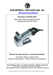
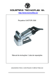
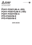
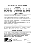
INSTALLATION
MANUAL
INSTALLATION & OPERATING INSTRUCTIONS
FOR RP007 - 060 SERIES
WATER SOURCE HEAT PUMPS
RP007 TO 060
CONTENTS
INTRODUCTION . . . . . . . . . . . . . . . . . . . . . . . . . . .3
PRE-INSTALLATION INSPECTION OF
EQUIPMENT. . . . . . . . . . . . . . . . . . . . . . . . . . . . . . 3
INSTALLATION . . . . . . . . . . . . . . . . . . . . . . . . . . . 3
PRODUCT NOMENCLATURE . . . . . . . . . . . . . . . . 4
START-UP AND OPERATION . . . . . . . . . . . . . . . 10
MAINTENANCE . . . . . . . . . . . . . . . . . . . . . . . . . . .11
Complete Table of Contents on following pages.
NOTES, CAUTIONS AND WARNINGS
Installer should pay particular attention to the words:
NOTE, CAUTION, and WARNING. Notes are intended to
clarify or make the installation easier. Cautions are given
to prevent equipment damage. Warnings are given to
alert installer that personal injury and/or equipment damage may result if installation procedure is not handled
properly.
CAUTION:
READ ALL SAFETY GUIDES BEFORE YOU
BEGIN TO INSTALL YOUR UNIT.
SAVE THIS MANUAL
036-21521-001-A-0103
036-21521-001-A-0103
TABLE OF CONTENTS
PRODUCT NOMENCLATURE . . . . . . . . . . . . . . . . . 3
INTRODUCTION . . . . . . . . . . . . . . . . . . . . . . . . . . . . 3
PRE-INSTALLATION INSPECTION OF EQUIPMENT . . . . 4
RIGGING . . . . . . . . . . . . . . . . . . . . . . . . . . . . . . . . . . . . . . . 4
INSTALLATION . . . . . . . . . . . . . . . . . . . . . . . . . . . . 4
CLEARANCES REQUIRED . . . . . . . . . . . . . . . . . . . . . . . . . 6
UNIT MOUNTING . . . . . . . . . . . . . . . . . . . . . . . . . . . . . . . . 6
DUCT CONNECTIONS . . . . . . . . . . . . . . . . . . . . . . . . . . . . 6
ELECTRICAL POWER SUPPLY AND CONNECTIONS . . . 6
ROOM THERMOSTAT AND CONTROL WIRING . . . . . . . 7
BLOWER PERFORMANCE . . . . . . . . . . . . . . . . . . . . . . . . . 8
LOOP WATER SUPPLY AND PIPING
CONNECTIONS . . . . . . . . . . . . . . . . . . . . . . . . . . . . . . . . . . 9
SUPPLY/RETURN PIPING . . . . . . . . . . . . . . . . . . . . . . . . . 9
CONDENSATE DRAIN PIPING . . . . . . . . . . . . . . . . . . . . . 10
WATER REGULATING VALVE – INSTALLATION . . . . . . 10
START-UP AND OPERATION . . . . . . . . . . . . . . . . 10
START-UP . . . . . . . . . . . . . . . . . . . . . . . . . . . . . . . . . . . . . 11
WATER REGULATING VALVE - ADJUSTMENT . . . . . . . 11
MAINTENANCE . . . . . . . . . . . . . . . . . . . . . . . . . . . 11
STANDARD PRODUCT WARRANTY . . . . . . . . . . . . . . . . 17
2
LIST OF FIGURES
Fig. #
1
2
3
4
5
Pg. #
UNIT MOUNTING . . . . . . . . . . . . . . . . . . . . . . . . . . . . . 6
TYPICAL SINGLE PHASE WIRING DIAGRAM . . . . . 13
TYPICAL THREE PHASE WIRING DIAGRAM . . . . . 14
HORIZONTAL MODELS - DIMENSIONS . . . . . . . . . . 15
VERTICAL MODELS - DIMENSIONS . . . . . . . . . . . . . 16
LIST OF TABLES
Tbl. #
1
2
3
4
5
6
7
8
Pg. #
GENERAL DATA . . . . . . . . . . . . . . . . . . . . . . . . . . . . . 5
OPERATING LIMITS - WATER LOOP
APPLICATION . . . . . . . . . . . . . . . . . . . . . . . . . . . . . . . 5
ELECTRICAL DATA . . . . . . . . . . . . . . . . . . . . . . . . . . 7
BLOWER PERFORMANCE (CFM) . . . . . . . . . . . . . . . 8
UNIT WATER PRESSURE DROP . . . . . . . . . . . . . . . 10
R-22 REFRIGERANT CHARGE . . . . . . . . . . . . . . . . 12
HORIZONTAL MODELS - DIMENSIONS . . . . . . . . . 15
VERTICAL MODELS - DIMENSIONS . . . . . . . . . . . . 16
Unitary Products Group
036-21521-001-A-0103
PRODUCT NOMENCLATURE
Water Cooled Package Heat Pump and AC Model Number Nomenclature
R P 060 C00 V 2 L AB 1
Product Category
R = Watercooled ID Package,HP
Product Generation
1 = First Generation
Product Identifier
P = HP, R-22 High Efficiency
Nominal Cooling Capacity - MBH
007 = 0.5 Ton
009 = 0.75 Ton
012 = 1 Ton
018 = 1.5 Ton
024 = 2 Ton
030 = 2.5 Ton
036 = 3 Ton
048 = 4 Ton
060 = 5 Ton
Airflow
V = Vertical
H = Horizontal
Heat Type
C00 = No Heat Option
Additional Options
AA = None
AB = Insulated Water Circuit(Not available on cooling only)
AC = Cooling only (No Reversing Valve)
AD = Cupro Nickle Heat Exchanger
AE = Condensate Overflow Switch w/ Alarm output
AF = Remote Management Relay Pkg w/ Alarm output
INTRODUCTION
RP units are completely self-contained heating and/or
air conditioning units. This equipment employs a waterto-refrigerant heat exchanger to extract (heating cycle)
or reject (cooling cycle) heat from/to a circulating
water-loop.
All models 1/2 through 5 tons are shipped as factorycharged packages. Horizontal units are designed for
suspended ceiling mounting, and are constructed with
integral hanger channels. Vertical units are designed
for free-standing floor mounting. All units are shipped
completely factory wired and pre-piped. Water supply,
water outlet, and condensate drain connections are via
female threaded pipe fittings.
Each refrigeration circuit includes an adjustable bi-flow
expansion valve, liquid line filter drier, and multiple service gauge ports. External high pressure and low pressure protection switches are included in each
compressor circuit. Heat Pump models feature a pilot
operated, sliding piston type, 4-way reversing valve
with a replaceable magnetic solenoid coil.
Unitary Products Group
Installation Options
L = Left Hand Return
R = Right Hand Return
Voltage
1 = 208/230-1-60
2= 208/230-3-60
4 = 460-3-60
5 = 575-3-60
AG = AB + AE
AH = AB + AF
AJ = AC = AD
AK = AC = AE
AL = AC = AF
The coaxial water-to-refrigerant heat exchanger, and
all water piping within the unit are rated for water side
working pressures up to 400 psig. Automatic water flow
regulating valves are available as field installed accessories.
All units are completely factory wired with all necessary
operating controls. A 24 volt control circuit, with oversize transformer, is provided for field connection. Units
are designed to operate with conventional thermostat
control interface. The reversing valve solenoid coil
shall be energized in cooling mode only. A manual
reset lock-out relay is provided to disable the compressor control circuit in the event of high/low pressure cutout.
These units are designed for indoor installation only.
They are not intended or approved for outdoor installation.
3
036-21521-001-A-0103
PRE-INSTALLATION INSPECTION OF
EQUIPMENT
All units are factory tested to ensure safe operation and
quality assembly. Units are packaged and sealed on
wooden skid runners and shipped in first class condition. Torn and broken packaging, scratched or dented
panels should be reported to carrier immediately. Internal inspection of all units should be performed prior to
installation . Remove all access doors and check for
visual defects that can occur during transport. Any
problems found internally should be reported to carrier
and manufacturer immediately. Refrigerant circuit
should be checked to ensure no leaks have occurred
during shipment. Install gauge set to high and low pressure ports to confirm pressure has been maintained
and no leaks have occurred during shipment. Repair
any damage prior to installation to ensure safe operation.
NOTE: Record any unit damage on the Bill of Lading and
report to carrier and factory immediately. Shipping
and handling damages are not warranty items.
RIGGING
Prior to mounting unit, check individual unit
weights (page 4) and verify lifting capacity of lifting
equipment exceeds weight of units by safe margins. failure to do so may result in unit damage,
personal injury or even death.
INSTALLATION
Lock all electrical power supply switches in the
off position before installing the unit. Failure to
disconnect power supply may result in electrical
shock or even death.
Only qualified personnel should perform installation and service of this equipment.
Location - To ensure unit operates at maximum efficiencies, choose a dry indoor area where the temperature is controlled between 40° F and 115° F.
Consideration of surrounding areas should be taken
when choosing a location to install the unit. Common
vibration and sound levels associated with commercial
equipment may be objectionable to people or equipment.
Failure to allow adequate space between units
may result in poor unit performance and possible
unit failure.
Install thermostats, supply air ductwork, and return air
ductwork (if applicable) so that each unit will operate
only in a single cooling or heating zone. In order to
assure proper drainage of condensate, horizontal units
can be slightly pitched in the same direction as drain
pan outlet.
4
Unitary Products Group
036-21521-001-A-0103
TABLE 1: GENERAL DATA
Model Series
007
009
012
018
024
030
036
048
060
Nominal Cooling(Ton)
0.5
0.75
1.0
1.5
2.0
2.5
3.0
4.0
5.0
7000
9000
12800
18100
24200
30800
36100
48200
59000
12.4
13.0
12.6
14.4
14.4
13.5
14.2
14.0
12.6
8800
10700
14800
20900
27500
35200
41400
56000
72000
Cooling Performance
Cooling Capacity (BTUH)
EER
Heating Capacity (BTUH)
COP
Design CFM
Nominal Water flow (gpm)
Compressor-Type
Number Used
4.2
4.4
4.2
4.5
4.6
4.4
4.6
4.6
4.4
200
300
400
600
800
1000
1200
1600
2000
1.5
2.25
3.0
4.5
6.0
7.5
9.0
12.0
15.0
Rotary
Rotary
Rotary
Rotary
Recip.
Recip.
Recip.
Recip.
Recip.
1
1
1
1
1
1
1
1
1
Air Coil-Type
Enhanced Copper Tubes, Enhanced Aluminum Fins
Face Area (sq ft)
1.00
1.00
1.00
1.51
2.56
2.56
2.88
4.38
5.00
Rows/FPI
2/14
2/14
3/14
3/14
3/14
3/14
3/14
3/14
3/14
1/2" FPT
1/2" FPT
1/2" FPT
3/4" FPT
3/4" FPT
3/4" FPT
3/4" FPT
3/4" FPT
1"FPT
Water Coil-Type
Water Connection Size
Co-axial
Drain Connection Size
3/4" FPT
Direct Drive Fan-Type
Number Used
Centrifugal, Forward Curved
1
1
1
1
1
1
1
1
1
9x4
9x4
9x4
9x6
9x7
9x7
9x7
10x9
10x9
0.10/3
0.10/3
0.17/3
0.25/3
0.25/3
0.33/3
0.50/3
0.75/3
1.0/3
1-14x16x1
1-14x16x1
1-14x16x1
1-16x20x1
1-18x25x1
1-18x25x1
1-20x25x1
2-20x20x1
1-20x20x1
1-20x25x1
1-14x16x1
1-14x16x1
1-14x16x1
1-16x20x1
1-18x25x1
1-18x25x1
1-20x25x1
1-16x25x1
1-14x25x1
1-18x25x1
1-16x25x1
Operating
130
135
155
180
215
235
260
325
345
Shipping
145
150
170
195
230
255
280
345
365
Diameter x Width (in)
Motor HP/Speed
Filters
HWP - Quantity-Size (in)
VWP - Quantity-Size (in)
Weight
NOTE:
1. Performance calculated in accordance with ARI/ISO Standard 13256-1 for Water Loop application.
2. Cooling capacities are rated at entering air conditions of 80.6°F db / 66.2° F wb, 86° F entering water temperature.
3. Heating capacities are rated at entering air conditions of 68° F db / 59° F wb, 68° F entering water temperature.
TABLE 2: OPERATING LIMITS - WATER LOOP
APPLICATION
Min. Entering Water
Max. Entering Water
Normal Entering Water
1.
COOLING
HEATING
50°F
40°F1
110°F
80°F
60-90°F
50-70°F
Heating operation below 55°F requires insulated water circuit.
Unitary Products Group
5
036-21521-001-A-0103
CLEARANCES REQUIRED
Twenty-four (24) inch clearance is required on all sides
of the unit for service access. Service access doors are
equipped with lifting handles and are located on all
sides of the unit to allow easy servicing of all components.
UNIT MOUNTING
Vertical units should be mounted level on a vibration
absorbing pad(s) to minimize vibration transmission
through the floor structure. It is not necessary to anchor
the unit to the floor.
Horizontal units are typically suspended above a ceiling by threaded steel rods, securely anchored to the
building structure. Units should be supported from the
holes in the rail extensions at the four corners, using
steel threaded rods having a minimum diameter of 3/8
inch. Four rubber bushings are supplied with the unit to
be placed between the unit and the supporting rods to
absorb vibration.
3/8" THREADED
ROD (BY OTHERS)
INTEGRAL
SUPPORT
RAIL
WASHER
(BY OTHER)
DOUBLE HEX NUT
(BY OTHER)
FIGURE 1 : UNIT MOUNTING
DUCT CONNECTIONS
Canvas or other types of flexible collars are recommended for connecting the air ducts to the unit. The
supply air duct collar can be connected directly to the
blower outlet flange. Allowance must be made in the
supply duct for removal of the first duct section adjacent to the unit, for the servicing of the blower and
motor assembly. Return air may be ducted to the unit
or drawn directly from the ceiling space into the filter.
Supply ducts should be sized for an air velocity of not
more than 1000 feet per minute. Return ducts should
be sized for a velocity of not more than 700 feet per
minute. When the sound level is critical, it is recommended that both the supply and return
6
ducts be lined with acoustic insulation for the first ten
feet closest to the unit. The supply duct should also
have at least one elbow or tee upstream of the first outlet connection for good sound attenuation.
ELECTRICAL POWER SUPPLY AND CONNECTIONS
Before installing the unit, make sure that the voltage
and number of phases on the unit data plate are the
same as the available power supply. All wiring and
switchgear installed external to the unit must conform
to all applicable local codes. The maximum allowable
size of fuses or circuit breaker required is shown on the
unit data label. Fuses must be of the time delay type.
Unitary Products Group
036-21521-001-A-0103
The power supply wiring is to be connected directly to
the line side of compressor contactor as shown on the
connection wiring diagram. A ground wire must be connected to the ground lug marked GND in the electrical
control box.
ROOM THERMOSTAT AND CONTROL WIRING
so that constant fan operation can be selected if
desired. Heat Pump models require the installation of a
heating and cooling thermostat with a dedicated "O"
terminal for activating the reversing valve. Wiring
between the thermostat and the unit should be 18 Ga.
minimum. Appropriate room thermostats can be
ordered as an optional accessory for delivery with the
units if desired.
Any single stage 24-volt room thermostat can be used
with the “cooling only” models. It is recommended that
the thermostat sub-base should include a fan switch,
TABLE 3: ELECTRICAL DATA
COMPRESSOR
MODEL
SERIES
SUPPLY
VOLTAGE
007
208-230/1/60
1
009
208-230/1/60
1
012
208-230/1/60
018
208-230/1/60
024
030
036
048
060
QTY
BLOWER
MIN. CCT.
AMPACITY
MAX FUSE /
CCT. BKR. AMP
RLA
LRA
HP
FLA
@
2.8
17.7
0.10
0.9
4.35
15
@
3.4
23.0
0.10
0.9
5.15
15
1
@
4.8
26.3
0.17
1.4
7.40
15
1
@
6.4
38.0
0.25
1.5
9.5
15
208-230/1/60
1
@
10.4
49.0
0.25
1.5
14.50
20
208-230/1/60
1
@
12.4
61.0
0.33
2.6
18.10
30
208-230/3/60
1
@
7.7
55.0
0.33
2.6
12.23
15
208-230/1/60
1
@
15.3
82.0
0.50
3.2
22.33
35
208-230/3/60
1
@
10.0
68.0
0.50
3.2
15.70
25
460/3/60
1
@
4.8
34.0
0.50
1.9
7.90
15
208-230/1/60
1
@
19.0
105.0
0.75
4.9
28.65
45
208-230/3/60
1
@
14.0
91.0
0.75
4.9
22.40
35
460/3/60
1
@
5.9
42.0
0.75
2.2
9.58
15
575/3/60
1
@
4.8
34.0
0.75
1.8
7.80
15
208-230/1/60
1
@
24.6
132.0
1.00
5.1
35.85
60
208-230/3/60
1
@
16.0
97.0
1.00
5.1
25.10
40
460/3/60
1
@
8.2
50.0
1.00
3.2
13.45
20
575/3/60
1
@
5.0
44.0
1.00
2.6
8.85
15
Unitary Products Group
7
036-21521-001-A-0103
A simple method for approximating sufficient air volume is to measure the difference between the supply
and return air temperatures. In Heating mode, the air
temperature rise should be in the range of 20ºF to 30ºF.
In Cooling mode, the temperature drop should be
between 15ºF to 25ºF. If values are outside the appropriate range, increase or reduce the motor speed as
necessary.
BLOWER PERFORMANCE
All units employ direct-drive blower motors with multiple speed taps available. The motors have been
selected to deliver the nominal air volume against varying external static pressures when necessary. After
installation of the unit, it will be necessary to check the
air volume and change the motor speed connection
accordingly if the air volume is too high or too low. All
units are factory-wired with the medium speed winding
connected.
TABLE 4: BLOWER PERFORMANCE (CFM)
EXTERNAL STATIC PRESSURE (in w.g.)
UNIT
007
009
012
018
024
030
036
048
060
Note:
SPEED
0
0.1
0.2
0.3
0.4
0.5
0.6
0.7
0.8
High
-
-
-
-
270
235
195
150
-
Med
-
-
260
240
210
175
-
-
-
Low
225
215
200
180
150
-
-
-
-
High
-
-
380
360
330
290
240
-
-
Med
350
340
325
300
270
235
-
-
-
Low
285
275
260
240
210
-
-
-
-
High
495
475
450
420
385
345
300
-
-
Med
470
455
430
400
365
325
-
-
-
Low
385
370
355
330
300
-
-
-
-
High
-
-
705
660
610
555
495
430
-
Med
-
700
660
615
565
510
450
-
-
Low
690
665
630
585
535
480
-
-
-
High
-
-
1005
950
890
820
740
650
-
Med
925
905
875
840
790
730
660
-
-
Low
-
-
780
765
725
660
590
-
-
High
-
-
1170
1120
1060
985
905
810
-
Med
1150
1125
1090
1045
990
925
850
765
-
Low
-
975
970
940
905
855
785
-
-
High
-
1390
1330
1270
1210
1140
1055
960
-
Med
1355
1320
1270
1215
1155
1085
1005
920
-
Low
1200
1190
1170
1130
1085
1020
950
-
-
High
-
-
1990
1915
1835
1750
1660
1550
1415
Med
1880
1860
1820
1770
1710
1640
1550
1450
1320
Low
-
1490
1485
1480
1460
1420
1360
1285
1160
High
2340
2280
2210
2140
2070
1990
1895
1790
1660
Med
2040
2030
2005
1970
1925
1860
1785
1700
1590
Low
-
-
1705
1700
1680
1660
1610
1540
-
Units are shipped pre-wired for Medium speed.
All airflow ratings are at lowest voltage rating of dual rating (i.e., 208 volt)
Airflow ratings include resistance of wet coil and clean air filters.
8
Unitary Products Group
036-21521-001-A-0103
LOOP WATER SUPPLY AND PIPING
CONNECTIONS
The recommended circulating water supply for heat
pump systems is a closed-water loop, utilizing a cooling tower and boiler to maintain the loop temperature
within acceptable temperature limits. Typically, the
closed loop temperature is maintained above 60° F and
below 90° F. All units function independently, either
adding heat to the loop (cooling mode) or removing
heat from the loop (heating mode).
When utilizing an open cooling tower (evaporative
type), chemical treatment is mandatory to ensure that
the loop water is free of corrosive minerals. A secondary heat exchanger between the open cooling tower
and the closed water loop may also be used. It is
imperative that all air is purged from the closed loop
side to prevent condenser fouling.
Dual acting water regulating valves should be used
when there is potential for low fluid flow and/or low fluid
temperature or high fluid temperature conditions to
exist. These water regulating valve assemblies consist
of a direct acting valve parallel coupled to a reverse
acting valve. The direct acting valve opens in response
to an increase in discharge pressure during cooling
mode. The reverse acting valve opens in response to a
decrease in suction pressure during heating mode.
The heat rejection water source for cooling-only units
may be from a municipal supply main, a cooling tower,
or a chilled water system. An automatic water flow regulating valve is normally required, except if the inlet
water temperature is constant and the flow rate can be
pre-set and turned on and off by some other means,
such as a dedicated pump circuit or solenoid valve.
Unitary Products Group
Automatic water flow regulating valves, for both heat
pump and cooling-only applications, are available as
field installed accessories. The valves are installed on
the water outlet connection from the unit. Schrader
type refrigerant pressure access fittings are included
as standard in all units.
SUPPLY/RETURN PIPING
Supply and return piping should be as large as the unit
connection sizes (larger on long pipe runs). Never use
flexible hoses of a smaller inside diameter than that of
the nominal water pipe size. Both supply and return
water lines will sweat if subjected to low water temperatures. Insulate these lines as necessary to prevent condensation damage.
Flexible hoses should be used between the unit and
rigidly mounted piping to avoid vibration transmission.
Teflon tape thread sealant is recommended. Do not
overtighten threaded connections. Ball valves should
be installed in the supply and return lines for unit isolation and water flow balancing. Before final connection
to the unit, the supply and return hoses should be connected together and the piping system flushed to
remove any dirt or foreign material.
Pressure and temperature ports are recommended in
both the supply and return lines for system flow balancing. The water flow can be accurately set by measuring
the water-side pressure drop through the unit. See the
flow versus pressure drop specification table for application information. Do not exceed the recommended
water flow rates. Damage due to erosion of the
water-to-refrigerant heat exchanger could occur.
9
036-21521-001-A-0103
TABLE 5: UNIT WATER PRESSURE DROP
UNIT MODEL
007
EWT
oF
50
60
70
85
100
009
012
018
024
036
048
060
WPD
(psi)
WPD
(psi)
GPM
WPD
(psi)
GPM
WPD
(psi)
GPM
WPD
(psi)
GPM
WPD
(psi)
GPM
WPD
(psi)
GPM
WPD
(psi)
GPM
WPD
(psi)
1.0
0.8
1.35
1.4
1.8
2.1
2.75
2.3
3.5
3.3
4.5
3.6
5.5
2.9
7.5
3.9
9.0
3.6
1.5
2.0
2.25
3.5
3.0
5.3
4.50
5.7
6.0
8.0
7.5
9.0
9.0
7.0
12.0
9.6
15.0
8.8
1.0
0.7
1.35
1.4
1.8
2.0
2.75
2.2
3.5
3.2
4.5
3.5
5.5
2.8
7.5
3.7
9.0
3.5
1.5
1.9
2.25
3.4
3.0
5.1
4.50
5.5
6.0
7.7
7.5
8.7
9.0
6.8
12.0
9.2
15.0
8.5
1.0
0.7
1.35
1.3
1.8
1.9
2.75
2.1
3.5
3.0
4.5
3.3
5.5
2.6
7.5
3.5
9.0
3.3
1.5
1.8
2.25
3.2
3.0
4.8
4.50
5.2
6.0
7.3
7.5
8.2
9.0
6.4
12.0
8.7
15.0
8
1.0
0.7
1.35
1.2
1.8
1.8
2.75
2.0
3.5
2.9
4.5
3.1
5.5
2.5
7.5
3.3
9.0
3.1
1.5
1.7
2.25
3.0
3.0
4.6
4.50
4.9
6.0
6.9
7.5
7.8
9.0
6.1
12.0
8.3
15.0
7.6
1.0
0.6
1.35
1.2
1.8
1.7
2.75
1.9
3.5
2.7
4.5
3.0
5.5
2.4
7.5
3.2
9.0
3.0
1.5
1.6
2.25
2.9
3.0
4.4
4.50
4.7
6.0
6.6
7.5
7.5
9.0
5.8
12.0
7.9
15.0
7.3
CONDENSATE DRAIN PIPING
Horizontal Units - The 3/4 FPT drain connection on the
unit is NOT internally trapped. The cooling coil compartment and drain pan are under negative pressure
when the blower is running, therefore a P trap MUST
be used in the drain line.
It is recommended that a ¾ inch drain line be sloped
(¼ inch/foot) all the way to an open drain. Each unit
must be installed with its own individual trap, and have
the means to flush out the condensate line if necessary. If it is not possible to reach an open drain by gravity flow, a pump kit, which is available as an accessory,
can be mounted close to the unit.
Vertical Units - Each unit utilizes a flexible hose inside
the cabinet as a trapping loop. An external P-trap is not
necessary.
The water regulating valve is to be installed in the
water outlet line, as close as possible to the unit cabinet (maximum 18 inches distance). The capillary tube
from the sensing bellows on the valve(s) must be connected to the ¼ inch male flare connection, which is on
the refrigerant liquid line in the condenser compartment. Connect the capillary tube flare nut directly to the
unit male flare fitting. When one is making this connection, it is normal for some refrigerant to escape as the
schrader valve core is being opened and the nut is
being tightened. Complete the tightening of the nut as
soon as possible to minimize the loss of refrigerant. Do
not over-tighten.
GPM
GPM
START-UP AND OPERATION
NOTE: The services of a qualified Refrigeration Service
Mechanic should be employed in the start-up and
commissioning of these systems.
Lock all electrical power supply switches in the off
position before installing the unit. failure to disconnect power supply may result in electrical shock or
even death.
After completing the installation, and before energizing
the power supply to the unit, the following checks
should be made •
Verify that the electrical supply to the unit is of the
correct voltage, and rated for sufficient amperage
in accordance with the nameplate values.
•
Verify that the low voltage wiring between the unit
and the thermostat is correct.
•
Confirm that the water piping is complete and free
of leaks.
•
Check that the water flow rate is correct, and adjust
as necessary.
•
Confirm that the blower wheel rotates freely.
•
All service access panels are in place and properly
secured.
WATER REGULATING VALVE – INSTALLATION
10
030
A room thermostat should be used to cycle the unit on
and off automatically as required to maintain the room
temperature at the set point of the thermostat. The air
Unitary Products Group
036-21521-001-A-0103
circulating fan will cycle on and off with the compressor.
If desired, the air circulating fan can be run continuously.
The units have a lock out relay that will prevent the unit
from cycling on the low pressure cut out or the high
pressure cut out. If either of these safety devices open,
the compressor will not restart when the safety device
resets. To restart the compressor after a safety lock
out, it will be necessary to interrupt the power to the
control circuit. This can be done at the thermostat or at
the disconnect switch.
START-UP
1. Set the thermostat to the highest setting.
2. Set the fan switch to the 'AUTO' position, and the
thermostat system switch to 'COOL'.
3. Reduce the thermostat setting to approximately 5
degrees below room temperature.
4. The compressor, and the supply air blower, will
start. Simultaneously the reversing valve will be
energized.
5. After five minutes, verify cooling mode operation by
checking for cool air discharge at the supply air
outlet.
6. Set the thermostat system switch to the 'OFF' position. The unit will stop running, and the reversing
valve will de-energize.
7. Allow approximately five minutes to allow for system pressures to equalize.
8. Set the thermostat to its lowest temperature setting.
9. Move the thermostat system switch to 'HEAT'.
10. Increase the thermostat setting approximately 5
degrees above room temperature.
11. After five minutes, verify heating mode operation
by checking for warm air discharge at the supply
air outlet.
12. Adjust the thermostat to maintain the desired
space temperature.
13. Check the unit for unusual vibrations, noises,
leaks, etc.
Unitary Products Group
WATER REGULATING VALVE - ADJUSTMENT
The water regulating valve needs to be adjusted to
maintain a condensing pressure of 170 to 220 PSIG.
The valve is adjusted by turning the ¼ inch square
shaft on top of the spring housing. Turning the adjusting screw counter clockwise will raise the opening
pressure and raise the condensing pressure being
maintained. Turning the adjusting screw clockwise will
lower the opening point and lower the condensing
pressure being maintained. If mains water is being
used, make sure the valve closes soon after the compressor stops. If the flow does not stop after a few minutes, raise the opening pressure by turning the
adjusting shaft counter clockwise until the flow stops.
If the unit is running on mains water, we recommend
adjusting the water regulating valve to give 100ºF leaving water temperature or 220 PSIG condensing temperature. This will give the best compromise between
low water flow and high operating efficiency. If the condenser water is being re-circulated through a cooling
tower or a chilled water system, it is recommended that
the water regulating valve be set for a lower condensing temperature. This will provide higher efficiency,
lower operating cost and a lower sound level. The minimum condensing pressure required for satisfactory
expansion valve operation is 170 PSIG.
MAINTENANCE
The air circulating fan motor has bearings that are factory lubricated and sealed for long life. No further lubrication is required. The compressor is part of a sealed
refrigeration system that does not require any additional lubrication.
Filter changes are required at regular intervals. It is
suggested that the filter be checked at 60-day intervals
for the first year of operation, until field experience is
acquired. If light cannot be seen through the filter, it
should be changed. Always replace the filter with the
same size of 1-inch thick disposable type of fiberglass
filter. (See General Data for listing of required filter
sizes.)
The condensate drain pan should be checked annually,
and cleaned and flushed as required.
Recording of reference operating parameters is recommended (volts, amp draw, water temperature differences, etc.). A comparison of logged data with start-up
and annual data is useful as an indicator of general
equipment condition.
11
036-21521-001-A-0103
Periodic lockouts are almost always caused by air or
water problems. The lockout of the compressor is a
normal protective result of insufficient heat transfer.
Check for dirt in the water system, insufficient water
flow rates, excessive water temperatures, air flow rates
(dirty filters), and air temperatures.
TABLE 6: R-22 REFRIGERANT CHARGE
12
UNIT
SIZE
CAPACITY
TONS
HORIZONTAL
VERTICAL
060
5.0
5 lbs. – 8 oz.
5 lbs. – 13 oz.
048
4.0
4 lbs. – 6 oz.
4 lbs. – 9 oz.
036
3.0
3 lbs. – 5 oz.
3 lbs. – 7 oz.
030
2.5
2 lbs. – 12 oz.
2 lbs. – 14 oz.
024
2.0
2 lbs. – 4 oz.
2 lbs. – 6 oz.
018
1.5
1 lbs. – 12 oz.
1 lbs. – 14 oz.
012
1.0
1 lbs. – 6 oz.
1 lbs. – 7 oz.
009
0.75
1 lbs. – 1 oz.
1 lbs. – 1 oz.
007
0.50
10 oz.
10 oz.
Unitary Products Group
036-21521-001-A-0103
APPLIES TO ALL
208/230-1-60 SINGLE
PHASE MODELS
Note: Solenoid Valve (SV) used
on Heat Pump version only.
FIGURE 2 : TYPICAL SINGLE PHASE WIRING DIAGRAM
Unitary Products Group
13
036-21521-001-A-0103
APPLIES TO MODELS:
RP030, RP036, RP048
& RP060
NOTE: Solenoid Valve (SV) used
on Heat Pump version only.
FIGURE 3 : TYPICAL THREE PHASE WIRING DIAGRAM
14
Unitary Products Group
036-21521-001-A-0103
FIGURE 4 : HORIZONTAL MODELS - DIMENSIONS
TABLE 7: HORIZONTAL MODELS - DIMENSIONS
A
B
C
D
E
F
007
34.50
19.00
15.00
32.25
21.50
009
34.50
19.00
15.00
32.25
21.50
012
34.50
19.00
15.00
32.25
018
40.00
21.00
16.00
024
45.00
21.00
030
45.00
036
RETURN AIR
G
H
J
2.56
15.00
2.00
12.00
2.56
15.00
2.00
12.00
21.50
2.56
15.00
2.00
37.75
23.50
2.56
18.00
18.00
42.75
23.50
2.25
21.00
18.00
42.75
23.50
48.00
23.00
20.00
45.75
048
58.00
25.00
20.00
060
63.00
25.00
20.00
Unitary Products Group
K
SUPPLY AIR
N
L
M
5.75
6.81
10.31
3.75
5.75
6.81
10.31
3.75
12.00
5.75
6.81
10.31
3.75
1.00
14.00
6.50
8.25
10.31
3.75
25.00
1.00
16.00
6.50
9.19
10.31
4.81
2.25
25.00
1.00
16.00
6.50
9.19
10.31
4.81
25.50
2.25
25.00
1.00
18.00
6.50
9.19
10.31
5.88
55.75
27.50
2.25
38.99
1.00
18.00
6.00
12.25
11.38
5.13
60.75
27.50
2.25
42.00
1.00
18.00
6.00
12.25
11.38
5.13
15
FIGURE 5 : VERTICAL MODELS - DIMENSIONS
TABLE 8: VERTICAL MODELS - DIMENSIONS
AIR SUPPLY
C
007
22.50
22.50
33.00
009
22.50
22.50
33.00
6.81
10.31
2.00
7.81
14.88
12.50
1.25
N/A
N/A
012
22.50
22.50
33.00
6.81
10.31
2.00
7.81
14.88
12.50
1.25
11.50
12.00
018
22.50
22.50
35.00
8.25
10.31
2.00
7.13
16.88
14.50
1.25
11.50
12.00
024
22.50
22.50
45.00
9.19
10.31
2.00
7.13
16.88
23.50
1.25
11.50
12.00
030
22.50
22.50
45.00
9.19
10.31
2.00
6.63
16.88
23.50
1.25
11.50
12.00
036
24.50
24.00
45.00
9.19
10.31
3.00
7.63
18.88
23.50
1.25
12.50
12.50
048
29.50
27.50
52.00
12.25
11.38
3.00
8.63
23.00
28.50
0.75
14.19
14.31
060
29.50
27.50
56.00
12.25
11.38
3.00
8.81
23.00
32.50
0.75
14.19
14.31
D
E
10.31
G
2.00
7.81
OPTIONAL
PLENUM
B
6.81
F
RETURN AIR
A
Subject to change without notice. Printed in U.S.A.
Copyright © by Unitary Products Group 2003. All rights reserved.
Supersedes: Nothing
Unitary
Products
Group
5005
York
Drive
K
L
M
P
R
14.88
12.50
1.25
N/A
N/A
036-21521-001-A-0103
Norman
OK
73069