1
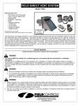
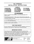
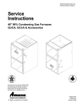
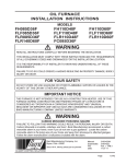
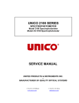
OIL FURNACE
INSTALLATION INSTRUCTIONS
MODELS
FH085D36D
FLF085D36D
FLR110D48D
FH110D48D
FLR085D36D
FLR140D60D
FH110D60D
FLF110D48D
FC085D36D
WARNING
READ ALL INSTRUCTIONS CAREFULLY BEFORE BEGINNING THE
INSTALLATION.
THIS INSTALLATION MUST COMPLY WITH THESE INSTRUCTIONS AND
THE REQUIREMENTS OF ALL GOVERNING CODES AND ORDINANCES FOR
THE INSTALLATION LOCATION.
IT IS THE RESPONSIBILITY OF INSTALLER TO KNOW AND UNDERSTAND
ALL OF THESE REQUIREMENTS.
FAILURE TO DO SO COULD CREATE A HAZARD RESULTING IN PROPERTY
DAMAGE, BODILY INJURY OR DEATH.
FOR YOUR SAFETY
DO NOT STORE OR USE GASOLINE OR OTHER FLAMMABLE VAPORS OR
LIQUIDS IN THE VICINITY OF THIS OR ANY OTHER APPLIANCE.
IMPORTANT NOTICE
THIS FURNACE IS NOT INTENDED FOR USE AS A CONSTRUCTION
HEATER. USE OF THIS FURNACE DURING CONSTRUCTION AND FINISHING
PHASES OF A STRUCTURE IS CONSIDERED AS "OPERATION IN A
CORROSIVE ATMOSPHERE" AND "UNUSUAL, NEGLIGENT OR IMPROPER
USE" AND AS SUCH ARE CONSIDERED EXCLUSIONS BY THE BARD
MANUFACTURING COMPANY LIMITED WARRANTY.
Bard Manufacturing Company
Bryan, Ohio 43506
Since 1914...Moving ahead just as planned.
Manual:
Supersedes:
File:
Date:
2100-392
VOL. I, TAB 3
08-06-01
Copyright 2001
CONTENTS
Getting Other Information and Publications
Installation and Operating Instructions
Equpment Selection ............................................... 2
Locating the Furnace .............................................. 2
Duct Work ............................................................... 6
Wiring
............................................................... 6
Oil Line Piping ........................................................ 8
Beckett AFG Oil Burner .......................................... 8
Beckett “CleanCut” Oil Pump ................................. 9
Beckett Solid State Igniter ...................................... 9
Beckett R7184B Primary Control ............................ 9
Beckett R7184B Primary Operational Guide ........ 10
Burner Set up and Adjustments ........................... 11
Burner Nozzle and Electrode Adjustments ........... 14
Ventilation and Combustion Air ............................ 14
Louvers and Grilles ............................................... 18
Venting
............................................................. 18
Thermostat ........................................................... 18
Fan & Limit Control ............................................... 18
TABLES
Table 1
Table 2
Table 3
Table 4
Table 5
Table 6
Table 7
Table 8
Table 9
Table 10
Table 11
Table 12
Table 13
Table 14
i
Minimum Clearances ............................. 2
Dimensions Lo-Boy Models .................. 3
Dimensions Hi-Boy Models .................... 4
Dimensions Counterflow Models ............ 5
Electrical Data ........................................ 7
Furnace Data ........................................ 11
Correlation of % of CO2, O2 and
Reserve Air .......................................... 13
No. 2 Fuel Oil Efficiency Chart ............. 13
Recommended Start-Up Settings ........ 13
Round Duct Sizing ............................... 14
Sq.Ft. Required as
Unconfined Space ................................ 15
Minimum Ventilation Openings ............. 16
Temperature Rise Ranges, Limit
Control Settings, and
Heating Blower Speeds ........................ 19
Filter Sizes for Gas Furnaces ............... 20
Filters
Hi-Boy Models – Filter Locations & Removal
and Replacement Procedures .............................. 20
Counterflow Models – Filter Locations ............... 21
Lo-Boy Models – Filter Locations ....................... 22
Maintenance
Lubrication ............................................................ 23
Inspect Air Filter .................................................... 23
Final Inspeciton and Test ...................................... 23
Service Hints ........................................................ 23
Combination Combustion Chamber/Burner
Mounting System .................................................. 24
To Remove Burner Only ....................................... 24
To Remove Entire Combustion Chamber
Mounting System .................................................. 24
Common Causes of Trouble ................................. 26
Care of Finish ....................................................... 26
Cleaning of Furnace ............................................. 26
Blower System Resistance Curves ................ 27-30
Wiring Diagrams ............................................. 31-33
FIGURES
Figure 1
Figure 2
Figure 3
Figure 4
Lo-Boy Models Dimensions ............... 3
Hi-Boy Models Dimensions ................ 4
Counterflow Models Dimensions ....... 5
Typical Installation Requirement
Front Flue .......................................... 7
Figure 5
Typical Single Inside
Tank Installation ................................. 8
Figure 6
Pressure Gauge Connection to
Pressure Gauge Port ....................... 12
Figure 7
Electrode Adjustments ..................... 14
Figure 8
All Air From Inside Building .............. 15
Figure 9
All Air From Outdoors ...................... 16
Figure 10
All Air From Outdoors Through
Ventilated Attic ................................. 17
Figure 11
All Air From Outdoors - Inlet Air
From Ventilated Crawl Space and
Outlet Air to Ventilated Attic ............. 17
Figure 12
Typical Installation of 16x25x1
Filter Rack ........................................ 20
Figure 13
Typical Installation of 20x25x1
Filter Rack ........................................ 20
Figure 14
Filter Installation - Counterflow
Models ............................................. 21
Figure 15
Filter Installation - Lo-Boy Models ... 24
Figure 16A Removal of Burner Only .................. 20
Figure 16B Removal of Entire Combustion
Chamber Mounting System ............. 25
GETTING OTHER INFORMATION and PUBLICATIONS
These publications can help you install the furnace. You
can usually find these at your local library or purchase
them directly from the publisher. Be sure to consult
current edition of each standard.
FOR MORE INFORMATION, CONTACT
THESE PUBLISHERS:
ACCA
Air Conditioning Contractors of America
1712 New Hampshire Ave. N.W.
Washington, DC 20009
Telephone: (202) 483-9370
Fax: (202) 234-4721
ANSI
American National Standards Institute
11 West Street, 13th Floor
New York, NY 10036
Telephone: (212) 642-4900
Fax: (212) 302-1286
ASHRAE
American Society of Heating Refrigerating,
and Air Conditioning Engineers, Inc.
1791 Tullie Circle, N.E.
Atlanta, GA 30329-2305
Telephone: (404) 636-8400
Fax: (404) 321-5478
NFPA
National Fire Protection Association
Batterymarch Park
P.O. Box 9101
Quincy, MA 02269-9901
Telephone: (800) 344-3555
Fax: (617) 984-7057
National Fuel Gas Code ........... ANSI Z223.1/NFPA54
National Electrical Code ...................... ANSI/NFPA 70
Standard for the Installation .............. ANSI/NFPA 90A
of Air Conditioning and Ventilating Systems
Standard for Warm Air ...................... ANSI/NFPA 90B
Heating and Air Conditioning Systems
Standard for Chimneys, Fireplaces, Vents ... NFPA 211
and Solid Fuel Burning Appliances
Load Calculation for .......................... ACCA Manual J
Residential Winter and Summer Air Conditioning
Duct Design for Residential .............. ACCA Manual D
Winter and Summer Air Conditioning
and Equipment Selection
Manual 2100-392
Page
1
INSTALLATION and OPERATING INSTRUCTIONS
EQUIPMENT SELECTION
LOCATING THE FURNACE
An accurate heating load calculation must be conducted
using American Society of Heating, Refrigeration and
Air Conditioning Engineers (ASHRAE) or Air
Conditioning Contractors of America (ACCA) manuals.
Do not add a large safety factor above the calculated
value. If the calculated heating load requirement
exceeds the heating capacity rating of a given model,
use only the next larger size available. Never increase
by any more than absolutely necessary based upon
available equipment heating capacities. Always select
based upon heat capacity (output), never use input
capacities.
When installing the furnace be sure to provide adequate
space for easy service and maintenance. Locate the
furnace as close to the chimney as practical, giving
consideration to the accessibility of the oil burner,
controls, and blower for service. Allow a minimum of
24 inches at front of furnace for servicing oil burner.
Allow adequate room for filter and blower
maintenance. Clearance from combustible material as
stated on the furnace and repeated in Table 1 must be
maintained. For damp basement installations, a raised
concrete pad is recommended. This will help keep the
bottom of the furnace dry and reduce rusting.
NOTE: It is the personal responsibility and obligation
of the purchaser to contract a qualified
installer to assure that installation is adequate
and is in conformance with governing codes
and ordinances.
An oil burner must have a generous supply of
combustion air to operate properly. The flow of
combustion and ventilating air must not be obstructed
from reaching the furnace. See “Ventilation and
Combustion Air” section.
The furnace area must be kept clear and free of
combustible materials, gasoline and other flammable
vapors and liquids.
This unit is not designed for mobile home or trailer
installations. Always install furnace in a level position.
TABLE 1
MINIMUM CLEARANCES
Minimum Installation Clearances - - Inches
Furnace
Plenum
1
Minimum Service
Clearances
Front
B ack
Sides
Top
Sides
D u ct
Flue
Pipe
Floor
Front
B ack
Sides
FH085D36D
FH110D48D
FH110D60D
4
4
4
1
1
1
2
2
2
2
2
2
2
2
2
2
2
2
9
9
9
C
C
C
24
24
24
-------
-------
F LF 085D 36D
FLR085D36D
FLF110D48D
6
6
6
0
18
0
2
2
2
2
2
2
2
2
2
2
2
2
9
9
9
NC
NC
NC
24
24
24
24
24
24
18 *
18 *
18 *
FLR110D48D
FLR140D60D
F C 085D 36D
6
6
6
18
18
1
2
2
2
2
2
2
2
2
2
2
2
2
9
9
9
NC
NC
NC **
24
24
24
24
24
---
18 *
18 *
---
Model
j
C
NC
*
**
For the first three (3) feet from plenum. After three (3) feet, no clearance required.
Combustible flooring
Noncombustible floor
Maintained on one side or the other to achieve filter access and/or blower service.
Floor must be noncombustible. For furnace only installation can be installed on combustible
flooring only when installed on special base part no. CFB7 available from factory. When air
conditioning coil cabinet DCB23-22 is used then use special base part no. CFB23.
Manual 2100-392
Page
2
TABLE 2
LO-BOY MODELS
DIMENSIONS (INCHES)
Plenum
Openings
Cabinet
Model
Number
A
Width
B
Depth
C
DxE
Height Supply
DxF
Return
G
Dia.
H
Location
F LF 085D 36D
FLR085D36D
23
23
47-1/4
47-1/4
40-1/4
40-1/4
22x20
22x20
22x16
22x16
Front
Rear
6
6
--34
FLR110D48D
FLR110D48D
23
23
47-1/4
47-1/4
44-1/4
44-1/4
22x20
22x20
22x16
22x16
Front
Rear
6
6
FLR140D60D
26
50
50
25x20
25x16
Rear
6
j
Air Filters 1
Flue Connection
J
Siz e
N o.
U sed
5-1/4
---
16 x 20 x 1
16 x 20 x 1
1
1
--38
5-1/4
---
20 x 20 x 1
20 x 20 x 1
1
1
43-5/8
---
20 x 25 x 1
1
Washable type filter 1” nom. thickness
FIGURE 1
LO-BOY MODELS DIMENSIONS
MIS-1345
Manual 2100-392
Page
3
TABLE 3
HI-BOY MODELS
DIMENSION (INCHES)
Cabinet
Model
Number
FH085D36D
FH110D48D
FH110D60D
Plenum Openings
A
Width
B
Depth
C
Height
DxE
Supply
FxH 2
Return
G
Flue Dia.
Filter Siz e
23
23
23
31-1/2
31-1/2
31-1/2
56
60
60
22x20
22x20
22x20
23x14
23x14
23x14
6
6
6
16 x 25
16 x 25
20 x 25
j
k
1
Washable type filter
Left or right side return air option. Must be cut in by installer.
FIGURE 2
HI-BOY MODELS DIMENSIONS
MIS-1346
Manual 2100-392
Page
4
TABLE 4
COUNTERFLOW MODELS
DIMENSION (INCHES)
Cabinet
Plenum Openings
Model
Number
A
Width
B
Depth
C
Height
DxE2
Return
FxH
Supply
G
Flue Dia.
F C 085D 36D
23
29-1/2
56
22 x 20
18 x 19
6
j
k
1
Filter Siz e
10 x 20
15 x 20
Washable type filter
Left or right side return air option. Must be cut in by installer.
FIGURE 3
COUNTERFLOW MODELS DIMENSIONS
MIS-1344
Manual 2100-392
Page
5
DUCT WORK
The air distribution system should be designed and
installed in conformance with manuals published by Air
Conditioning Contractors of America (ACCA) as set
forth in Manual D, or ASHRAE publications.
On replacement installations, particularly if equipment
is oversized, the duct systems can easily be undersized.
Modifications may be required to assure that the
equipment is operating within the approved
temperature rise range when under full rated input
conditions, and that no short cycling on limit controls is
occurring.
IMPORTANT
When a furnace is installed so that supply
ducts carry air circulated by the furnace to
areas outside the space containing the
furnace, the return air must also be handled
by a duct(s) sealed to the furnace casing and
terminating outside the space containing the
furnace This is to prevent drawing possible
hazardous combustion products into the
circulated air.
When the furnace is used in connection with a cooling
unit*, the furnace shall be installed parallel with or on
the upstream side of the cooling unit to avoid
condensation in the heating element. With a parallel
flow arrangement, the dampers or other means used to
control flow of air shall be adequate to prevent chilled
air from entering the furnace, and if manually operated,
must be equipped with means to prevent operation of
either unit, unless the damper is in the full heat or cool
position.
* A cooling unit is an air conditioning coil, heat pump
coil or chilled water coil.
See CFM versus static pressure tables on pages 23-26
for additional information.
INADEQUATE SUPPLY AIR and/or RETURN
AIR DUCT SYSTEMS
Short cycling because of limit control operation can be
created by incorrectly designed or installed supply and/
or return air duct systems.
The duct systems must be designed using ASHRAE or
ACCA design manuals and the equipment CFM and
external static pressure ratings to insure proper air
delivery capabilities.
Manual 2100-392
Page
6
INSTALLING THE FURNACE
A typical installation is shown in Figure 4. All parts of
the furnace installation (furnace, oil tank and piping
systems, combustion and ventilation air, venting, etc.)
must comply with NFPA31, Installation of Oil Burning
Equipment -- latest edition. This drawing shows the
typical connecting parts needed to correctly install this
furnace. Make sure that all parts of the heating system
comply with the local codes.
Check the furnace and your load calculation to verify
that the unit is properly sized. (Refer to Equipment
Selection” section on Page 2.)
The correct size of unit needed may be substantially
smaller than the unit being replaced due to home
improvements and technology advancements since the
initial installation.
WIRING
FACTORY
All units are fully factory wired. Multispeed blowers
are factory wired on high speed for cooling/manual fan
operation. Heating speeds are wired for the largest
input and may need lower speed for field installed low
input nozzle. If replacement wire is necessary, use 105
degrees C minimum. See electrical data, Table 5.
FIELD
All wiring must conform to the National Electrical
Code and all local codes. A separate fuse or breaker
should be used for the furnace.
FIGURE 4
TYPICAL INSTALLATION REQUIREMENTS
FRONT FLUE LO-BOY MODEL SHOWN
MIS-1335
NOTE:
The chimney must be lined with a high temperature noncorrosive material that complies with the local
codes, or in their absence with Standard for Chimneys and Vents, NFPA211. Also see section on Venting
in these instructions.
TABLE 5
ELECTRICAL DATA
Blow er Motor
Burner Motor
Max. Time
Delay Fuse
or HACR
Circuit Breaker
Model
Volts-HZ-PH
Total
Amps
HP
FLA
HP
FLA
Minimum
Circuit
Ampacity
FH085D36D
115-60-1
9.2
1/3
7.5
1/7
1.7
15
15
FH110D48D
115-60-1
12.2
1/2
10.5
1/7
1.7
16
20
FH110D60D
115-60-1
14.2
3/4
12.5
1/7
1.7
19
20
F LF 085D 36D
115-60-1
17.3
1/3
5.6
1/7
1.7
15
15
FLR085D36D
115-60-1
17.3
1/3
5.6
1/7
1.7
15
15
FLF110D48D
115-60-1
12.2
1/2
10.5
1/7
1.7
16
20
FLR110D48D
115-60-1
12.2
1/2
10.5
1/7
1.7
16
20
FLR140D60D
115-60-1
14.2
3/4
12.5
1/7
1.7
19
20
F C 085D 36D
115-60-1
7.3
1/3
5.6
1/7
1.7
15
15
Manual 2100-392
Page
7
OIL LINE PIPING
First determine whether the pipe system is to be a single
line system or a two line system. All connections must
be absolutely air tight or you will have a malfunction of
the burner. When installing the piping, a good oil filter
should be installed close to the burner. A single line
system is recommended for gravity feed.
A typical single inside tank installations shown in
Figure 5. For installation details for this and other tank
configurations, refer to NFPA31 -- latest edition. All
tank and pipe setups must comply with NFPA31.
These controls were selected for their proven high
quality, dependability, and serviceability. With proper
maintenance this burner assembly will provide many
years of reliable service.
All units are shipped with the oil burner installed, and
with high rate oil nozzle installed designed for use with
No. 1 or No. 2 fuel oil. Inspect firepot refractory
before firing to be sure it has not been jarred out of
position in shipment. Burner air tube must not
extend beyond inside surface of firepot. Burner
head should be centered on the combustion chamber
opening. See Figures 16A and 16B.
BECKETT AFG OIL BURNER
This furnace is equipped with a high static Beckett AFG
oil burner which is designed to produce adequate draft
in nearly any vertically vented application. The burner
employees the latest time tested controls of the highest
quality. The controls consist of a high voltage Beckett
solid state igniter, a Beckett “CleanCut” oil pump with
an integral solenoid valve, and a Beckett R7184B
primary control.
WARNING
Never attempt to use gasoline in your furnace.
Gasoline is more combustible than fuel oil and
could result in a serious explosion causing
damage, injury or death.
FIGURE 5
TYPICAL SINGLE INSIDE TANK INSTALLATION
MIS-1340
Manual 2100-392
Page
8
The following is a detailed explanation of each control
included in the Becket AFG Oil Burner, how each
operates, how to set up the burner, and how to
troubleshoot problems should they occur.
BECKETT “CLEANCUT” OIL PUMP
This oil pump is equipped with an oil solenoid valve
installed in the pump housing. This feature provides
quick cutoffs resulting in reduction in smoke after the
burner shuts down. This is a time proven pump design
and is capable of both one and two pipe systems. This
pump requires a pre-purge style primary control such as
the R7184B primary. All installation and set up
instructions are outlined in the “Oil Pump
Specification” section of the installation instructions
manual.
As an improved service feature Bard Manufacturing has
installed a brass tee fitting next to the oil line output of
the pump for installing a pressure gauge to ensure the
correct pump pressure. Refer to the “Burner Set Up and
Adjustment” section in the manual.
BECKETT SOLID STATE IGNITER
This igniter differs from the traditional iron core
transformer in that it produces a 14,000 volt spark
instead of a 10,000 volt spark of the iron core
transformer. This hotter spark provides for cleaner,
faster ignitions. Being solid state technology this
igniter is less susceptible to problems caused by voltage
variations. It also has a greater ability to ignite cold
and/or inconsistent oil. The solid state igniter is wired
to the primary control the same as a standard iron core
transformer.
BECKETT R7184B PRIMARY CONTROL
The R7184B Interrupted Electronic Oil Primary is a
line voltage, safety rated, interrupted ignition oil
primary control for residential oil burners. The R7184B
used with a cad cell flame sensor, operates the oil
burner and oil valve. The primary controls fuel oil,
senses flame, controls ignition spark and is designed to
notify a remote alarm circuit before going into lockout
when equipped with a flame monitoring system.
This primary control, though it possesses the latest
technology, is a very simple control to operate and
provides additions troubleshooting features to ease
service and reduce down time. Once the features and
operation of this control are understood the service
person will find it a welcomed addition. In an effort to
help in the transition to the R7184B primary control the
operational guide is provided following on Page 10.
Manual 2100-392
Page
9
BECKETT R7184B PRIMARY
OPERATIONAL GUIDE
Pre-Purge Delay – 15 seconds on delay
LED Codes – Flashing 1/2 second on / 1/2 second off – system is locked out or in restricted mode
(hard lockout).
– Flashing 2 seconds on / 2 seconds off – control is in recycle mode (soft lockout).
– ON – CAD cell is sensing flame
– OFF – CAD cell is not sensing flame.
Ignition Trials – On any given call for heat the
control will allow three ignition trials. After the
three trials the control will go into a soft lockout
mode. The LED will flash 2 seconds on and 2
seconds off when in this recycle mode. The
control may then be reset by pressing the RED
reset button on the control. If within the same
original call for heat the control will again allow
three ignition trials followed by another soft
lockout and a 2 second on / 2 second off LED
code. The control my be reset one additional time
by pressing the red reset button. This will allow
three final ignition trials. If all three of the final
ignition trials fail then the control goes into a hard
lockout or Restricted Mode. This series of ignition
failures must all occur with the original call for
heat in order to reach the Restricted Mode. The
LED will now flash 1/2 second on / 1/2 second off
indicating the restricted mode. The control can be
resurrected from the restricted mode only by
pressing and holding the red reset button for
approximately 30 seconds until the LED flashes
twice. Removing unit power or resetting the
thermostat will not reset the control
Checking CAD Cell – With a call for heat and the burner ignited, press and release the red reset button.
The LED will go out and then flash 1, 2, 3, or 4 times before returning to the run mode. The CAD cell
resistance must be below 1600 ohms for proper operation.
– 1 flash
– Less than 400 ohms
– 2 flashes – More than 400 and less than 800 ohms
– 3 flashes – More than 800 and less than 1600 ohms
– 4 flashes – More than 1600 and less than 5000 ohms
Future Option – Flame Quality Monitor
This control is trained to recognize and remember
a good flame based on initial burner set up.
Control then monitors the flame via the CAD cell
signal for deviation in the combustion
characteristics of the burner. If the control senses
a deviation on the high side or on the low side
from the original set up condition for three
consecutive cycles, it will trigger an alarm circuit
which can be tied to an audible local device to
signal the home owner or into the home security
Manual 2100-392
Page
10
system. Upon being notified of the of the alarm,
the security agency will notify the dealer of choice
based upon information supplied by the home
owner. The system will also be capable of being
connected to a phone line that will contact the
dealer directly with the alarm. This alarm will
typical sound 3 to 5 days prior to the primary
control going into lockout giving the service
agency a prior notice before a sooting condition or
other failure can occur resulting in untold savings.
TABLE 6
FURNACE DATA
Furnace Installed Standard
2
1
Field Installed Option
2
1
Model Number
Noz z le
Siz e
Input
B TU H
Heating
Capacity
B TU H
F LF 085D 36D
.75
105,000
85,000
.65
91,000
75,000
FLR085D36D
.75
105,000
85,000
.65
91,000
75,000
FLF110D48D
1.00
140,000
115,000
.85
119,000
98,000
FLR110D48D
1.00
140,000
115,000
.85
119,000
98,000
FLR140D60D
1.25
175,000
141,000
1.10
154,000
125,000
F C 085D 36D
.75
105,000
84,000
.65
91,000
74,000
FH085D36D
.75
105,000
84,000
.65
91,000
74,000
FH110D48D
1.00
140,000
113,000
.85
119,000
96,000
FH110D60D
1.00
140,000
113,000
.85
119,000
96,000
j
k
Noz z le
Siz e
Input
B TU H
Heating
Capacity
B TU H
70 degree hollow cone spray pattern, 100 PSIG pump pressure
Annual fuel utilization efficiency and heating capacity based upon U.S.
Government standard test using D.O.E. isolated combustion rating
procedure.
BURNER SETUP AND ADJUSTMENTS
All oil burner installations should be performed by a
qualified installer in accordance with regulations of the
National Fire Protection Standard for Oil-Burning
Equipment, NFPA31 -- latest edition, and in complete
compliance with all local codes and authorities having
jurisdiction. A qualified installer is an individual or
agency who is responsible for the installation and
adjustments of the heating equipment and who is
properly licensed and experienced to install oil-burning
equipment in accordance with all codes and ordinances.
The proper installation and adjustment of any oil burner
requires technical knowledge and the use of combustion
test instruments. The following procedure must be
followed to correctly adjust the burner to match the
specific characteristics of the installation.
IMPORTANT
Always use combustion test instruments when
making burner adjustments and draft gauge
when setting the barometric damper. It is
virtually impossible to make accurate and
reliable adjustments using the “eyeball”
method.
CHECK AND ADJUSTMENT PROCEDURE:
1. Check all oil lines and connections for leaks.
2. Connect pressure gauge to pressure gauge port in
brass tee fitting. See Figure 6.
3. Operate the burner for 5 - 10 minutes so that the
system is near steady state temperature conditions.
4. Check fuel pump pressure, and adjust to 100 PSIG
if necessary.
5. Set the overfire draft to -.02” W.C. by adjusting the
barometric damper. The sample tube can be
inserted into the heat exchanger over the
combustion chamber by loosening the two (2)
screws securing the sliding door on the hinged
burner observation door.
6. A small diameter hole will be required in the flue
pipe between the flue connection on the furnace
and the barometric damper for purposes of taking
the smoke tests and measuring the CO2 (or O2) and
flue gas temperature.
7. The burner air adjustment shutters are factory set to
the recommended start up settings as shown in
Table 9. These settings are for initial start up only.
Reduce or increase the air supply until a trace of
smoke is obtained on the smoke tester. This is a
reference point only not the final adjustment.
Manual 2100-392
Page
11
8. Measure the CO2 (or O2) in the flue gas at the trace
of smoke level. Open the air control and add
reserve air until the CO2 is lowered by 1.5%.
Example: Original CO2 at trace of smoke level was
13.0% (3.30% O2). Lower to 11.5% CO2 (5.3% 02).
See Table 7.
9. Perform the smoke test again. It should now be at
zero. Lock the air settings securely.
10. Measure the stack temperature. Subtract the room
temperature to obtain the net reading and use the
Efficiency Chart, Table 8, to determine the steadystate efficiency.
FIGURE 6
PRESSURE GAUGE CONNECTION TO PRESSURE GAUGE PORT
MIS-1660
Manual 2100-392
Page
12
TABLE 7
CORRELATION OF PERCENT OF CO2, O2
AND RESERVE AIR
Carbon
Dioxide
Oxygen
Reserve Air
(Approx.)
15.4
15.0
14.5
0.0
0.6
1.2
0.0
3.0
6.0
14.0
13.5
13.0
2.0
2.6
3.3
10.0
15.0
20.0
12.5
12.0
11.5
4.0
4.6
5.3
25.0
30.0
35.0
11.0
10.5
10.0
6.0
6.7
7.4
40.0
45.0
50.0
TABLE 8
NO. 2 FUEL OIL EFFICIENCY CHART
(NET STACK TEMP. DEGREES F)
% O2
200
250
300
350
400
450
500
550
600
650
700
750
800
% O2
1
89.6
88.4
87.3
86.2
85.1
84.0
82.9
81.7
80.6
79.5
78.4
77.3
76.2
14.7
2
89.4
88.2
87.0
85.9
84.7
83.6
82.4
81.2
80.1
78.9
77.7
76.6
75.4
14.0
3
89.2
87.9
86.7
85.5
84.3
83.1
81.9
80.7
79.4
78.2
77.0
75.8
74.6
13.2
4
88.9
87.7
86.4
85.1
83.8
82.6
81.3
80.0
78.7
77.5
76.2
74.9
73.6
12.5
5
88.7
87.3
86.0
84.6
83.3
82.0
80.6
79.3
77.9
76.6
75.3
73.9
72.6
11.7
6
88.4
87.0
85.5
84.1
82.7
81.3
79.9
78.5
77.0
75.6
74.2
72.8
71.4
11.0
7
88.0
86.5
85.0
83.5
82.0
80.5
79.0
77.5
76.0
74.5
73.0
71.5
70.0
10.3
TABLE 9
RECOMMENDED START-UP SETTINGS
Factory Installed
1
Field Installed Option
1
Furnace
Model No.
Burner Style
Part No.
Noz z le
Air Band
Setting
Air Shutter
Setting
Noz z le
Air Band
Setting
Air Shutter
Setting
FH085D36D
AFG/9020-026
.75
0
6
.65
0
5
FH110D48D
AFG/9020-027
1.00
2
10
.85
0
8
FH110D60D
AFG/9020-027
1.00
2
10
.85
0
8
F LF 085D 36D
AFG/9020-026
.75
0
6
.65
0
5
FLF110D48D
AFG/9020-027
1.00
2
10
.85
0
8
FLR085D36D
AFG/9020-028
.75
0
6
.65
0
5
FLR110D48D
AFG/9020-029
1.00
2
10
.85
0
8
FLR140D60D
AFG/9020-030
1.25
0
8
1.10
0
6
F C 085D 36D
AFG/9020-026
.75
0
6
.65
0
5
j
70 degree hollow cone spray pattern, 100 PSIG pump pressure
Manual 2100-392
Page
13
BURNER NOZZLE AND ELECTRODE
ADJUSTMENTS
Check nozzle size as to conformance to installation
requirements. Install nozzle by screwing into hexagon
adapter. Refer to recommended start-up setting in
Table 9.
SPACING OF ELECTRODES
The electrodes should be spaced 5/32” apart. They
should extend 1/16” beyond the end and 5/16” above
the center of the nozzle tip as shown in Figure 7
GUN ASSEMBLY ADJUSTMENT
The gun assembly can be adjusted in the slot inside of
fan housing by loosening screw holding slot cover in
position. Nozzle tip should ordinarily be located 1-1/8”
behind the front face of the cone.
REMOVING GUN ASSEMBLY
VENTILATION AND COMBUSTION AIR
Appliances shall be installed in a location where the
facilities for ventilation permit satisfactory combustion
of oil, proper venting and the maintenance of ambient
temperature at safe limits under normal conditions of
use. Applications shall be located in such a manner as to
not interfere with proper circulation of air within the
confined space. When building are so tight that normal
infiltration does not meet air requirements, outside air
shall be introduced. Ducts used to convey air from the
outdoors shall be of the same cross-sectional area as the
free area of the opening to which they connect. The
minimum dimensions of rectangular air ducts shall be
not less than 3 inches (76 mm). See Table 10 for
information on round duct sizing.
For residence-type installations and similar usages, the
requirements normally may be obtained by application
of one of the methods shown in Figures 8 thru 11
following.
Disconnect the oil line at the fan housing and remove
lock nuts on copper tube fitting. Loosen igniter hold
down clamps, then swing igniter up and backward. Gun
assembly can now be removed through this opening.
TABLE 10
ROUND DUCT SIZING
4,000 BTUH
Per Square Inch
Round Duct Siz e
Total
B TU H
Input
4-3/8
5-1/8
60,000
80,000
5-1/4
5-7/8
85,000
105,000
6-1/8
6-1/4
115,000
120,000
6-3/4
6-7/8
140,000
145,000
7-1/4
8
160,000
200,000
FIGURE 7
ELECTRODE ADJUSTMENTS
1-1/8
5/32 GAP
ELECTRODE
5/16
1/16
NOZZLE
MIS-160
Manual 2100-392
Page
14
APPLIANCES LOCATED IN CONFINED
SPACES
In unconfined spaces in buildings, infiltration may be
adequate to provide air for combustion, ventilation, and
dilution of flue gasses. However, in buildings of
unusually tight construction, additional air shall be
provided using the method described under “All Air
From Outdoors” in Figure 8.
An unconfined space (such as an open basement) must
have a minimum volume of 50 cubic feet per 1,000
BTUH of total of all appliances in area. Adjoining
rooms may be counted as one area only if there are not
doors between the rooms.
Shown in Table 11 are the required minimum areas in
square feet to qualify as an unconfined space for
various total BTUH input ratings. The table is based on
a room(s) with 8 foot ceiling heights.
If the unconfined space is within a building having
insufficient air because of tight construction, the air for
combustion and ventilation shall be obtained from
outdoors or from spaces freely communicating with the
outdoors. Under these conditions a permanent opening
or openings have a total free area of not less than one
square inch per 5,000 BTU per hour (28 square inches
per hour ) of total input rating of all appliances shall be
provided.
FIGURE 8
APPLIANCES LOCATED
IN CONFINED SPACES
ALL AIR FROM INSIDE THE BUILDING
TABLE 11
SQUARE FEET REQUIRED TO
QUALIFY AS UNCONFINED SPACE
Total
B TU H
Input
Unconfined Space
Minimum Area In
Square Feet
8' Ceiling Height
60,000
80,000
375
500
85,000
105,000
531
656
115,000
120,000
719
750
140,000
145,000
875
906
160,000
200,000
1000
1250
ALL AIR FROM INSIDE BUILDING
The confined space shall be provided with two
permanent openings, one near the top of the enclosure
and one near the bottom. Each opening shall have a
free area of not less than one square inch per 1,000
BTU per hour (140 square inches per gallon per hour)
of the total input rating of all appliances in the
enclosure freely communicating with interior areas
having in turn adequate infiltration from the outside.
(See Figure 8.) Also see Table 12 on the following
page for specific ventilation opening requirements for
the furnace only.
The flow of combustion and ventilating air must not
be obstructed from reaching the furnace.
NOTE: Each opening shall have a free area of
not less than one square inch per 1,000
BTU per hour (140 square inches per
gallon per hour) of the total input rating
of all appliances in the enclosure.
MIS-1336
Manual 2100-392
Page
15
TABLE 12
MINIMUM VENTILATION OPENINGS
Model
Min. Ventilation
Opening
Square Inch
FH085D36D
Recommended
Opening
(2 Required)
Siz e
Sq. In.
240
8 x 16
128
FH110D48D
280
9 x 18
162
FH110D60D
280
9 x 18
162
F LF 085D 36D
290
8 x 19
152
FLR085D36D
290
8 x 19
152
FLF110D48D
340
9 x 19
171
FLR110D48D
340
9 x 19
171
FLR140D60D
360
9.5 x 19
180
F C 085D 36D
240
8 x 16
128
ALL AIR FROM OUTDOORS
A. The confined space shall be provided with two
permanent openings, one in or near the top of the
enclosure and one in or near the bottom. The
openings shall communicate directly, or by means
of ducts with outdoors or to such spaces (crawl or
attic) that freely communicate with outdoors. (See
Figures 9, 10, & 11 .)
B. When directly communicating with outdoors or by
means of vertical ducts, each opening shall have a
free area of not less than one square inch per 4,000
BTU per hour (35 square inches per gallon per
hour) of total input rating of all appliances in the
enclosures. If horizontal ducts are used, each
opening shall have a free area of not less than one
square inch per 2,000 BTU per hour (70 square
inches per gallon per hour) of total input of all
appliances in the enclosure.
FIGURE 9
APPLIANCES LOCATED IN CONFINED SPACES
ALL AIR FROM OUTDOORS
NOTE: Each air duct opening shall have a free
area of not less than one square inch
per 2,000 BTU per hour (70 square
inches per gallon per hour) of the total
input rating of all appliances in the
enclosure.
MIS-1337
Manual 2100-392
Page
16
FIGURE 10
APPLIANCES LOCATED IN CONFINED SPACES
ALL AIR FROM OUTDOORS THROUGH VENTILATED ATTIC
NOTE: The inlet and outlet air openings
shall each have a free area of not
less than one square inch per
4,000 BTU per hour (35 square
inches per gallon per hour) of the
total input rating of all appliances
in the enclosure.
MIS-1338
FIGURE 11
APPLIANCES LOCATED IN CONFINED SPACES
ALL AIR FROM OUTDOORS
INLET AIR FROM VENTILATED CRAWL SPACE AND OUTLET AIR TO VENTILATED ATTIC
NOTE: The inlet and outlet air openings
shall each have a free area of not
less than one square inch per 4,000
BTU per hour (35 square inches per
gallon per hour) of the total input
rating of appliances in the
enclosure.
MIS-1339
Manual 2100-392
Page
17
LOUVERS AND GRILLES
FAN AND LIMIT CONTROL
In calculating free area for above ventilation and
combustion air requirements, consideration shall be
given to the blocking effect of louvers, grilles, or
screens protecting openings. Screens used shall not be
smaller than 1/4 inch (6.3 mm) mesh and shall be
readily accessible for cleaning. If the free area through
a design of louver or grille is known, it shall be used in
calculating the size opening required to provide the free
area specified. If the design and free area is not known,
it may be assumed that wood louvers will have 30-35
percent free area and metal louvers and grilles will have
60-75 percent free area.
The fan and limit control is factory installed in all units.
See Table 13 for factory settings. The fan on/off
settings may have to be varied due to the static pressure
imposed upon the system. The limit control is factory
set at maximum fixed stop allowable and must not be
reset.
VENTING
The flue pipe to the chimney must be the same size as
the flue outlet of the furnace, have no reductions, be of
a corrosion-resistant material, and have an upward pitch
of 1/4” for every foot of horizontal run. A barometric
damper is supplied with the furnace and should be
installed in the flue pipe observing the instructions
packaged with the damper control. The barometric
damper opening must be located in the same
atmospheric pressure zone as the combustion air inlet to
the furnace. This furnace must not be vented into the
same chimney with any solid fuel burning appliance.
Masonry chimneys must be lined with a listed system or
other approved material that will resist corrosion,
softening, or cracking from flue gas at temperatures up
to 1800° F. See Standard for Installation of Oil Burning
Equipment NFPA31 and Standard for Chimneys
NFPA211 for additional information.
When the installation is completed, measure the air
temperature in the discharge plenum and return air
plenum. The temperature rise across the unit should
fall within the “Rise Range” as shown in Table 13. It is
normally desirable to operate in the middle of the range
unless air conditioning or other installation
requirements make that unfeasible. The speed of the
blower may have to be either increased or decreased to
obtain this temperature. The blower is equipped with a
3 or 4 speed motor to make these adjustments.
The fan and limit control in the burner compartment
governs the blower operation by means of two
temperature selections. One lever is set at 140 degrees
for example to start the blower, and the other lever is at
a lower temperature, 110 degrees to stop the blower.
These settings may be varied to suit the homeowner’s
comfort. A greater temperature difference between
settings may result in less repetition of the blower
operation at the end of the heating cycle. A low “off”
temperature is recommended for longer blower
operation as this keeps the air of the home in more
constant circulation.
NOTE: On model FC085D36D the blower “on”
setting is timed to assure blower operation.
This blower “on” setting cannot be adjusted.
THERMOSTAT
NOTE: FC models do not wire directly to the
primary control. See wiring diagram on
Page 33.
These furnaces are designed to be controlled with any
24V heating or heating/cooling thermostat. The
heat/cool thermostats must be designed for independent
heat/cool transformer circuits to assure that the 24V
transformer built into the oil primary control does not
conflict with the main furnace 24V transformer. The
heat anticipator should be set at 0.20A. This is a
nominal setting. The thermostat circuit should be
checked to verify setting.
Manual 2100-392
Page
18
IMPORTANT
Do not set the blower “on” set point lever of
the combination fan/limit control above 150.
TABLE 13
TEMPERATURE RISE RANGES, LIMIT CONTROL SETTINGS,
AND HEATING BLOWER SPEEDS
Rise Ranges
Heating
Blow er
S p eed
Limit Setting
On
Off
.65
.75
70 - 100
60 - 90
Low
Med
170
170
110
110
90
90
FH110D48D
.85
1.00
70 - 100
60 - 90
Low
Med Low
170
170
110
110
90
90
FH110D60D
.85
1.00
60 - 90
60 - 90
Low
Med Low
170
170
110
110
90
90
F LF 085D 36D
.65
.75
60 - 90
60 - 90
Low
Med
230
230
140
140
110
110
FLF110D48D
.85
1.00
60 - 90
60 - 90
Med Low
Med High
230
230
140
140
110
110
FLR085D36D
.65
.75
60 - 90
60 - 90
Low
Med
250
250
140
140
110
110
FLR110D48D
.85
1.00
60 - 90
60 - 90
Med Low
Med High
240
240
140
140
110
110
FLR140D60D
1.10
1.25
60 - 90
60 - 90
Med Low
Med High
220
220
140
140
110
110
F C 085D 36D
.65
.75
70 - 100
60 - 90
Low
Med
180
180
110
110
90
90
1
Noz z le
FH085D36D
Model
j
70 degree hollow cone spray pattern, 100 PSIG pump pressure
Manual 2100-392
Page
19
FILTERS
All models are shipped with filters. See Table 14 for
sizes. See following information. Hi-Boy models are
supplied with an external filter rack which can be
installed on either left or right side. The counterflow
models require a bracket installation and final filter
location projects into return air plenum attachment for
furnace. See Figure 14. Refer to Figure 14 for Lo-Boy
models which have filters internally mounted in blower
compartment at rear of furnace.
HI-BOY MODELS – FILTER LOCATIONS,
& REMOVAL AND REPLACEMENT
PROCEDURES
16 x 25 x 1 external filter racks are supplied as standard
equipment for all FH models (20 x 25 x 1 is standard
for FH110D60D model). A 14 x 23 opening is to be cut
into either the left or right side of the furnace depending
upon installation requirements. See Figure 12 for
typical installation of a 16 x 25 x 1 filter rack centered
over the 14 x 23 cutout.
FIGURE 12
TYPICAL INSTALLATION OF A 16x25x1
FILTER RACK
MIS-1342
Manual 2100-392
Page
20
TABLE 14
FILTER SIZES FOR OIL FURNACES
Model
Siz e
FH085D36D
Hi-Boy
(1) 16x25x1 W
FH110D48D
Hi-Boy
(1) 16x25x1 W
FH110D60D
Hi-Boy
(1) 20x25x1 W
F LF 085D 36D
FLR085D36D
Lo-Boys
(1) 16x20x1 W
FLF110D48D
FLR110D48D
Lo-Boys
(1) 20x20x1 W
FLR140D60D
Lo-Boy
(1) 20x25x1 W
F C 085D 36D
Counterflow
(1) 10x20x1 W
(1) 15x20x1 W
FIGURE 13
TYPICAL INSTALLATION OF A 20x25x1
FILTER RACK
MIS-1343
Figure 13 shows a typical installation of a 20 x 25 x 1
filter rack. The same 14 x 23 cutout is required in the
furnace side, and the bottom of the filter rack is aligned
over the bottom of the 14 x 23 cutout. The top of the
filter rack rises approximately 6 inches above the top of
the cutout. The 3 inch depth of the filter rack provides
ample spacing between furnace side and leaving edge of
filter for the entire filter surface to be effective.
To remove filter from the filter rack (see Figures 12 &
13), remove the filter access cover and grasp the end of
the filter.
COUNTERFLOW MODELS – FILTER
LOCATIONS
Counterflow models normally have filters installed in
the return air plenum above the furnace unless a
common return air/filter grille is used.
The electrical switch should be turned “off” before the
front door to furnace is removed. After removing the
front door, remove the left side filter door in the upper
section of the furnace. Refer to Figure 14 for proper
filter locations.
This filter is the high velocity type foam filter which
may be washed and used over and over. Do not replace
it with a fiberglass disposable filter of the same size.
To replace filter, reverse the above procedure.
FIGURE 14
FILTER LOCATIONS FOR COUNTERFLOW MODELS
MIS-1341
Manual 2100-392
Page
21
LO-BOY MODELS – FILTER LOCATIONS
Lo-boy models have the filter installed in the return air cabinet section of the furnace. It is accessible from the rear of
the furnace by removing the blower/filter access door. The electrical switch should be turned “off” prior to removing
the access door. Refer to Figure 15 below.
FIGURE 15
FILTER INSTALLATION – LO-BOY MODELS
FLUE PIPE LOCATION
ON FLR MODELS ONLY
FILTER:
FLR/FLF08516x20x1
FLR/FLF110 20x20x1
FLR140
20x25x1
BLOWER
MIS-1332
Manual 2100-392
Page
22
MAINTENANCE
INSPECT AIR FILTER
Washable air filters are supplied with each furnace.
Washable filters should not be replaced with disposable
type. Clean filters before each heating season begins.
It is recommended that filters also be cleaned at least
twice during the heating season.
Be sure the new filters are set securely in the filter rack
so there can be no leakage around them. (See
instructions on inside of blower compartment door.)
FINAL INSPECTION AND TEST
Final inspection and test of an installation shall be
made to determine that the work has been done in full
accordance with regulations and according to the
highest standards for safety, performance and
appearance. Such an inspection and test should
indicate the following as a minimum:
1. Determine that all parts of the oil storage and
circulating system, including tank, piping and
burner, are free from oil leaks. Be sure that no oil
discharges from the nozzle when burner is not
operating.
2. Be sure that the suction line and pump have been
entirely vented of air so that the burner has
instantaneous oil shutoff at the nozzle and so that
the pump operates without an air noise.
3. Check the flame adjustment to determine that the
flame is clear, quiet, free of odor and oil nozzle is
of proper size for the furnace.
4. Test operation of burner by operating the
thermostat. First, set the thermostat above room
temperature. Burner should start. Second, set
thermostat below room temperature. Burner will
stop.
5. Check operation of burner primary control in
accordance with manufacturer’s instructions
included with the control. Following is the method
we recommend in checking the safety switch in
this primary control.
A. Flame Failure – Simulate by shutting off oil
supply manual valve while burner is on.
Within 9 seconds the control will shut the
burner down and flash a diagnostic code of
1/2 second on / 1/2 second off. Ignition and
motor stop and oil valve closes
B. Ignition Failure – Test by closing oil supply
while burner is off. Run through starting
procedure. The primary control will attempt
three trials for ignition. After three attempts,
the control will lockout.
C. Power Failure – Turn off power supply
while burner is on. When burner goes out,
restore power and burner will restart.
D. If operation is not as described, check wiring
and installation first. If trouble appears to be
in the control circuit, replace the flame
detector. If trouble still persists, refer to
“Common Causes of Trouble” section on
page 26.
SERVICE HINTS
Preventive maintenance is the best way to avoid
unnecessary expense, inconvenience, and retain
operating efficiency of your furnace. It is advisable to
have your heating system and burner inspected at
periodic intervals by a qualified serviceman. If trouble
develops, follow these simple checks before calling the
serviceman.
1. Make sure there is oil in tank and valve is open.
2. Make sure thermostat is set above room
temperature.
3. Make sure electrical supply to furnace is on and
fuses are not blown or circuit breakers tripped.
4. Reset safety switch of burner primary control.
CAUTION
Reset three (3) times only. More than three
resets can cause excessive oil to be pumped
into combustion chamber which could result in
explosion upon ignition.
5. Press thermal protector button of burner motor.
6. Make sure air filters are in place and are clean.
7. Make sure all air openings in furnace, all
ventilation and combustion air openings, all return
air grilles, and all warm air registers are
unobstructed and open.
Manual 2100-392
Page
23
COMBINATION COMBUSTION
CHAMBER/BURNER MOUNTING
SYSTEM
The furnace has been designed with a combustion
chamber mounting system that enables service
personnel to remove the combustion chamber, its
mounting system, and burner assembly as one unit for
inspection and/or service on the bench. It has also been
designed to remove the burner assembly independently
from the mounting system to perform basic annual
service and inspection. The mounting system is
completely adjustable so exact alignment between the
burner tube and combustion chamber may be assured
prior to installation into the furnace. See Figure 16A
and 16B.
WARNING
The procedures described in Figures 16A and
16B should be conducted only by a qualified
service technician.
Improper servicing could cause electric shock
hazard, fires or explosion resulting in damage,
injury or death.
FIGURE 16A
REMOVAL OF BURNER ONLY
(3) 7/16 INCH NUTS
MIS-1662
OIL BURNER
Manual 2100-392
Page
24
TO REMOVE BURNER ONLY
Disconnect fuel line, power cord and wires from T, T
on primary control. Loosen (3) 1/4 inch nuts securing
burner mounting flange. Twist burner counterclockwise
and pull straight back away from the furnace. (See
Figure 16A.)
TO REMOVE THE ENTIRE COMBUSTION
CHAMBER MOUNTING SYSTEM
Disconnect fuel line, power cord and wires from T, T
on primary control. Remove (6) 5/16 inch bolts from
around front plate. Next remove (2) 5/16 inch nuts
from upper right and left hand corners of the front plate.
Pull entire assembly straight back away from furnace.
Be careful not to tip assembly up or down as it may
damage the combustion chamber. (See Figure 16B.)
FIGURE 16B
REMOVAL OF ENTIRE COMBUSTION CHAMBER MOUNTING SYSTEM
(2) 5/16 INCH NUTS
SECURING FRONT
PLATE
(6) 5/16 INCH BOLTS
SECURING FRONT PLATE
MIS-509
NOTE:
PULL BURNER & CHAMBER
ASSEMBLY STRAIGHT BACK.
DO NOT ANGLE UP OR DOWN
TO PREVENT CHAMBER
DAMAGE.
Manual 2100-392
Page
25
COMMON CAUSES OF TROUBLE
CAUTION
To avoid accidents, always open main switch
(OFF position) when servicing the burner.
BURNER WILL NOT PRODUCE FLAME
Check oil level gauge to see that there is sufficient oil in
tank or tanks. Check the burner mounted relay control.
Do not adjust this control.
Check position of electrodes – incorrect position will
cause slow or delayed ignition. Clean electrodes and
nozzle. Check and clean strainer in pump. If oil line
filter is used, check filter condition.
If burner runs but there is no flame the fuel pump may
be air bound. Follow instructions for bleeding fuel
pump.
Check and make sure the solenoid valve on the oil
pump is being energized and opening.
BURNER STARTS OR STOPS TOO OFTEN
Limit control may be set too low. Make sure set point
indicator is against limit stop on dial. Refer to rating
plate for limit setting. Check heat anticipator setting on
thermostat.
NOZZLE PRODUCES A STRINGY FLAME
Worn tangential grooves in nozzle. Replace nozzle.
BASEMENT TANK HUM
Occasionally with a two-pipe installation there may be
a low return line hum. Eliminate hum by installing a
special anti-hum valve in the return line near pump.
HEAVY FIRE OR PULSATING FLAME.
These may occur after burner starts. It may be caused
by a slight oil leak in the fuel pump and cannot be
corrected except by replacing the pump. This happens
only when the burner is started.
CHATTERING SOUND OR HIGH PITCH NOISE
This noise from motor can usually be traced to where a
conduit or BX cable is fixed rigidly or attached to some
part of the building. Relieving this strain may eliminate
noise.
Manual 2100-392
Page
26
PUMP SQUEALS OR CHATTERS
This may be caused by air in pipes. Check all joints in
the oil supply pipe for leaks. Check strainer in pump; if
dirty, clean.
INSUFFICIENT HEAT
Check limit control setting. It may be that flame is not
allowed to stay on long enough to generate sufficient
heat in furnace to heat the house properly. If the proper
size furnace has been selected according to house
requirements and satisfactory heat is not obtained,
recheck the heating plant for size and capacity in
relation to house. Check for clogged filters.
Check and make sure the heat anticipator on the
thermostat is set correctly.
CARE OF FINISH
Your unit is painted with baked enamel. Like a good
piece of furniture, it has an excellent appearance and an
occasional waxing and dusting will keep it attractive for
years.
WARNING
Under no circumstance should a soot
deterioration device be used in the
combustion chamber. These products known
as “soot busters” or “soot sticks” are
comprised of chemicals that burn at very high
temperatures which may exceed the
temperature rating of the combustion chamber
material.
Use of these products are detrimental to the
life expectancy of the combustion chamber
and will destroy the chamber. Refer to the
“Cleaning of Furnace” section for proper
cleaning methods.
CLEANING OF FURNACE
All of these units have two clean out plugs for easy
cleaning of the heat exchanger. They are accessible
from the front of these units by removing the clean out
access cover in the burner compartment. The furnace
should be check annually by a qualified service
technician.
FH RESISTANCE CURVES
FH085D36D System Resistance Curves
CFM Standard Airflow
1400
1300
HIGH
1200
1100
MED.
1000
900
LOW
800
700
0
0.1
0.2
0.3
0.4
0.5
External Static Pressure in Inches of Water
FH110D48D System Resistance Curves
2000
CFM Standard Airflow
HIGH
1800
MED.HIGH
1600
1400
MED. LOW
1200
LOW
1000
800
0
0.1
0.2
0.3
0.4
0.5
External Static Pressure in Inches of Water
Manual 2100-392
Page
27
FH RESISTANCE CURVES
CFM Standard Airflow
FH110D60D System Resistance Curves
2400
2200
HIGH
2000
MED. HIGH
1800
1600
1400
1200
1000
0
0.1
0.2
0.3
0.4
External Stactic Pressure in Inches of Water
Manual 2100-392
Page
28
0.5
FLF / FLR RESISTANCE CURVES
FLF/R085D36D System Resistance Curves
CFM Standard Airflow
1500
HIGH
1400
1300
1200
MED.
1100
1000
900
LOW
800
700
0
0.1
0.2
0.3
0.4
0.5
External Static Pressure in Inches of Water
FLF/R110D48D System Resistance Curves
CFM Standard Airflow
2000
HIGH
1800
MED. HIGH
1600
1400
MED.
1200
1000
800
0
0.1
0.2
0.3
0.4
0.5
External Static Pressure in Inches of Water
Manual 2100-392
Page
29
RESISTANCE CURVES
FLR140D60D System Resistance Curves
CFM Standard Airflow
2800
HIGH
2600
2400
2200
2000
MED. HIGH
1800
1600
MED. LOW
1400
1200
LOW
1000
0
0.05
0.1
0.15
0.2
0.25
0.3
0.35
0.4
0.45
0.5
External Static Pressure in Inches of Water
CFM Standard Airflow
FC085D36D System Resistance Curves
1600
HIGH
1400
1200
MED.
1000
LOW
800
600
0
0.1
0.2
0.3
0.4
External Static Pressure in Inches of Water
Manual 2100-392
Page
30
0.5
Manual 2100-392
Page
31
Manual 2100-392
Page
32
Manual 2100-392
Page
33