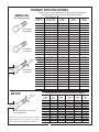
1
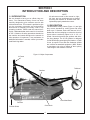
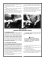
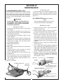
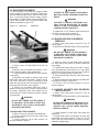
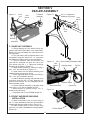
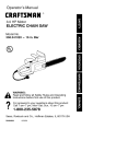
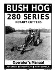
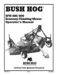
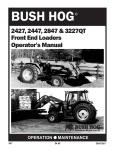
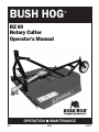
BUSH HOG
®
RZ 60
Rotary Cutter
Operator’s Manual
OPERATION l MAINTENANCE
907
$4.00
81652
CONGRATULATIONS!
You have invested in the best implement of its type on the market today.
The care you give your Bush Hog implement will greatly determine your satisfaction
with its performance and its service life. We urge a careful study of this manual to provide
you with a thorough understanding of your new implement before operating, as well as
suggestions for operation and maintenance.
If your manual should become lost or destroyed, Bush Hog will be glad to provide you with
a new copy. Order from Bush Hog, P. O. Box 1039, Selma, Alabama 36702-1039. Most of
our manuals can also be downloaded from our website at www.bushhog.com.
As an authorized Bush Hog dealer, we stock genuine Bush Hog parts which are
manufactured with the same precision and skill as our original equipment. Our trained
service personnel are well informed on methods required to service Bush Hog equipment,
and are ready and able to help you.
Should you require additional information or assistance, please contact us.
YOUR AUTHORIZED
BUSH HOG DEALER
BECAUSE BUSH HOG MAINTAINS AN ONGOING
PROGRAM OF PRODUCT IMPROVEMENT, WE
RESERVE THE RIGHT TO MAKE IMPROVEMENTS IN
DESIGN OR CHANGES IN SPECIFICATIONS WITHOUT INCURRING ANY OBLIGATION TO INSTALL
THEM ON UNITS PREVIOUSLY SOLD.
BECAUSE OF THE POSSIBILITY THAT SOME
PHOTOGRAPHS IN THIS MANUAL WERE TAKEN OF
PROTOTYPE MODELS, PRODUCTION MODELS MAY
VARY IN SOME DETAIL. IN ADDITION, SOME
PHOTOGRAPHS MAY SHOW SHIELDS REMOVED
FOR PURPOSES OF CLARITY. NEVER OPERATE
THIS IMPLEMENT WITHOUT ALL SHIELDS IN PLACE.
1
RAZORBACK ROTARY CUTTER
TABLE OF CONTENTS
SECTION/PARA
PAGE
IV.MAINTENANCE ..................................10
4-1 Maintenance Check List ................10
4-2 Lubrication .....................................10
4-3 Blade Replacement ......................11
4-4 Shear Bolt Replacement................11
4-5 Blade Holder & Gearbox Removal ......11
4-6 Blade Holder & Gearbox Installation..11
4-7 Troubleshooting .............................12
V. ASSEMBLY.........................................13
5-1 Base Unit Assembly......................13
5-2 Front & Rear Shielding Installation13
Safety Decals ......................................14
Torque Specifications..........................15
SECTION/PARA
PAGE
Warranty ................................................3
Dealer Preparation Check List ...............4
Safety Precautions.................................5
I. INTRODUCTION & DESCRIPTION ......6
1-1 Introduction ......................................6
1-2 Description.......................................6
II. PREPARATION FOR USE ....................7
III.OPERATING INSTRUCTIONS..............8
3-1 General Safety.................................8
3-2 Adjusting for Work ...........................8
3-3 Operation .........................................9
RETAIL CUSTOMER’S RESPONSIBILITY
UNDER THE BUSH HOG WARRANTY
It is the Retail Customer and/or Operator’s responsibility to read the Operator’s Manual, to
operate, lubricate, maintain and store the product in accordance with all instructions and
safety procedures. Failure of the operator to read the Operator’s Manual is a misuse of this
equipment.
It is the Retail Customer and/or Operator’s responsibility to inspect the product and to have
any part(s) repaired or replaced when continued operation would cause damage or excessive wear to other parts or cause a safety hazard.
It is the Retail Customer’s responsibility to deliver the product to the authorized Bush Hog
Dealer, from whom he purchased it, for service or replacement of defective parts which are
covered by warranty. Repairs to be submitted for warranty consideration must be made within forty-five (45) days of failure.
It is the Retail Customer’s responsibility for any cost incurred by the Dealer for traveling to or
hauling of the product for the purpose of performing a warranty obligation or inspection.
2
LIMITED WARRANTY
OOOOOOOOOOOOOOOOOOOOOOOOOOOOOOO
Bush Hog warrants to the original purchaser of any new Bush Hog equipment, purchased from an authorized
Bush Hog dealer, that the equipment be free from defects in material and workmanship for a period of one (1)
year for non-commercial, state, and municipalities’ use and ninety (90) days for commercial use from date of
retail sale. The obligation of Bush Hog to the purchaser under this warranty is limited to the repair or replacement of defective parts.
Replacement or repair parts installed in the equipment covered by this limited warranty are warranted for ninety (90) days from the date of purchase of such part or to the expiration of the applicable new equip-ment warranty period, whichever occurs later. Warranted parts shall be provided at no cost to the user at an authorized
Bush Hog dealer during regular working hours. Bush Hog reserves the right to inspect any equipment or parts
which are claimed to have been defective in material or workmanship.
DISCLAIMER OF IMPLIED WARRANTIES & CONSEQUENTIAL DAMAGES
Bush Hog’s obligation under this limited warranty, to the extent allowed by law, is in lieu of all warranties,
implied or expressed, INCLUDING IMPLIED WARRANTIES OF MERCHANTABILITY AND FITNESS FOR A
PARTICULAR PURPOSE and any liability for incidental and consequential damages with respect to the sale or
use of the items warranted. Such incidental and consequential damages shall include but not be limited to:
transportation charges other than normal freight charges; cost of installation other than cost approved by Bush
Hog; duty; taxes; charges for normal service or adjustment; loss of crops or any other loss of income; rental of
substitute equipment, expenses due to loss, damage, detention or delay in the delivery of equipment or parts
resulting from acts beyond the control of Bush Hog.
THIS LIMITED WARRANTY SHALL NOT APPLY:
1. To vendor items which carry their own warranties, such as engines, tires, and tubes.
2. If the unit has been subjected to misapplication, abuse, misuse, negligence, fire or other accident.
3. If parts not made or supplied by Bush Hog have been used in connection with the unit, if, in the sole judgement of Bush Hog such use affects its performance, stability or reliability.
4. If the unit has been altered or repaired outside of an authorized Bush Hog dealership in a manner
which, in the sole judgement of Bush Hog, affects its performance, stability or reliability.
5. To normal maintenance service and normal replacement items such as gearbox lubricant, hydraulic fluid,
worn blades, or to normal deterioration of such things as belts and exterior finish due to use or
exposure.
6. To expendable or wear items such as teeth, chains, sprockets, belts, springs and any other items that in the
company’s sole judgement is a wear item.
NO EMPLOYEE OR REPRESENTATIVE OF BUSH HOG IS AUTHORIZED TO CHANGE THIS LIMITED
WARRANTY IN ANY WAY OR GRANT ANY OTHER WARRANTY UNLESS SUCH CHANGE IS MADE IN
WRITING AND SIGNED BY BUSH HOG’S SERVICE MANAGER, POST OFFICE BOX 1039,
SELMA, ALABAMA 36702-1039.
OOOOOOOOOOOOOOOOOOOOOOOOOOOOOOO
Record the model number, serial number and date
purchased. This information will be helpful to your
dealer if parts or service are required.
MODEL NUMBER
SERIAL NUMBER
MAKE CERTAIN THE WARRANTY REGISTRATION
CARD HAS BEEN FILED WITH BUSH HOG/
SELMA, ALABAMA.
DATE OF RETAIL SALE
3
DEALER PREPARATION CHECK LIST
RAZORBACK ROTARY CUTTERS
BEFORE DELIVERING MACHINE — The following check list should be completed.
Use the Operator’s Manual as a guide.
r
r
r
r
r
r
r
r
r
1. Assembled completed.
2. Gearbox filled with oil.
3. All fittings lubricated.
4. All shields in place and in good condition.
5. All fasteners torqued to specifications given in Torque Chart.
6. All decals in place and readable. (See decal page.)
7. Overall condition good (i.e. paint, welds)
8. Operators manual has been delivered to owner and he has been instructed
on the safe and proper use of the cutter.
9. Purchaser or dealer elects to delete deflectors. (front belting, rear bands,
front and rear chains)
Explanation:
WARNING
For Non-Agricultural use, OSHA, ASAE, SAE and ANSI standards require the use of
Chain Guards or other protective guards at all times. Bush Hog strongly recommends
the use of such guards for Agricultural uses as well, to reduce the risk of property
damage, serious bodily injury or even death from objects thrown out by or from contact with the cutting blades.
Dealer’s
Signature
Purchaser’s
Signature
THIS CHECKLIST TO REMAIN IN OWNER’S MANUAL
It is the responsibility of the dealer to complete the procedures listed
above before delivery of this implement to the customer.
3
IMPORTANT SAFETY PRECAUTIONS
This symbol is used to call attention to safety precautions that should be followed by
the operator to avoid accidents. When you
see this symbol, carefully read the message
that follows and heed its advice. Failure to
comply with safety precautions could result
in serious bodily injury.
In addition to the design and configuration of equipment, hazard control and accident prevention are dependent upon the awareness, concern, prudence and proper training of personnel in the operation, transport,
maintenance and storage of equipment. Lack of attention to safety can result in accident, personal injury,
reduction of efficiency and worst of all—loss of life. Watch for safety hazards and correct deficiencies
promptly. Use the following safety precautions as a general guide to safe operations when using this
machine. Additional safety precautions are used throughout this manual for specific operating and maintenance procedures. Read this manual and review the safety precautions often until you know the limitations.
1.
2.
3.
4.
5.
6.
7.
8.
9.
10.
11.
12.
13.
14.
15.
16.
17.
18.
Read the Operator’s Manual. Failure to read the Operator’s Manual is considered a misuse of this
equipment.
Become familiar with all the machine’s controls and all the caution, warning and danger decals
affixed to the machine before attempting to start or operate.
Before starting or operating the machine, make a walk around inspection and check for obvious
defects such as loose mounting bolts and damaged components. Correct any deficiency before
starting.
Do not allow children to operate the cutter. Do not allow adults to operate it without proper instruction.
Do not carry passengers.
Keep the area of operation clear of all persons, particularly small children and pets. The operator
should cease mowing whenever anyone comes within the operating area.
Clear the work area of objects which might be picked up and thrown.
Use a piece of cardboard or wood rather than hands to search for hydraulic leaks. Escaping
hydraulic oil under pressure can penetrate skin. If fluid is injected into the skin, it must be surgically
removed within a few hours by a doctor familiar with this form of injury or gangrene may result.
Do not operate without all guards and shields in place and in good condition.
Lower implement to ground, stop tractor engine, apply parking brake, and allow blades to completely stop before leaving the tractor.
Keep hands and feet away from blades.
This cutter is not to be operated along highways or in any area where people may be present unless
all sides of the unit are enclosed by permanent bands, safety chains or other factory approved safety shields that are in good repair.
Wear personal protective equipment such as, but not limited to, protection for eyes, ears, feet,
hands and head when operating or repairing the equipment. Do not wear loose clothing or jewelry
that maycatch on equipment moving parts.
When performing adjustments or maintenance on the cutter, first lower it to the ground or block it
securely at a workable height.
Never stand between tractor and cutter while tractor is being backed to the cutter hitch.
Reduce speed when transporting cutter to avoid bouncing and momentary loss of steering.
Use tractor flashing warning lights, day or night, when transporting cutter on road or highways
unless prohibited by law.
In the event that someone other than yourself will operate this equipment we firmly suggest that all
SAFETY references be discussed prior to operation.
19. It is recommended that tractor be equipped with Rollover Protective System (ROPS) and seat belt
be used in all mowing operations.
5
SECTION I
INTRODUCTION AND DESCRIPTION
NOTE
All references made in this manual to right,
left, front, rear, top, and bottom are as viewed
as facing the direction of forward travel with
implement properly attached to tractor.
1-1 INTRODUCTION
We are pleased to have you as a Bush Hog customer. Your Razorback Rotary Cutter has been
carefully designed to give maximum service with
minimum down time. This manual is provided to give
you the necessary operating and maintenance
instructions for keeping your rotary cutter in top
operating condition. Please read this manual thoroughly. Understand what each control is for and how
to use it. Observe all safety precautions decaled on
the machine and noted throughout the manual for
safe operation of implement. If any assistance or
additional information is needed, contact your authorized Bush Hog dealer.
A-Frame
1-2 DESCRIPTION
The Razorback Rotary Cutters (Figure 1-1) are light
duty cutters intended for cutting grass and small
brush up to 1” diameter. Each cutter has two 3/8 x 3”
blades that are free-swinging to reduce the shock of
impact when a stationary object is hit. A 1/2 x 3”
Grade 2 shear bolt protects the gearbox and driveline from damage. The 35 HP gearbox is designed
for 540 RPM input speed giving the blades a 12,468
ft./min. tip speed. Front and rear discharge shields
are included as standard equipment. (Note: Dealer
or purchaser may elect to delete at their option)
Total weight of the machine is 450 lbs.
Figure 1-1 Major Components
Tailwheel
Gearbox
Rear Metal Band
Driveline
Flexible Shield
Cutter Deck
6
SECTION II
PREPARATION FOR USE
NOTE
Tractor should have 25 -35 PTO horsepower.
It is recommended that front end ballast, wheel
weights and/or fluid in tires be used to
increase stability.
F. Hold driveline sections parallel to each other
and check for minimum 5 inches (15cm) overlap.
(Figure 2-2) If driveline has been marked for cutting,
overlap will be the distance between two marks. If
driveline has less than minimum overlap, do not use.
Contact authorized Bush Hog dealer.
A. Attach cutter to Category I 3-point hitch per tractor operator’s manual. Do not comnnect driveline at
this time.
NOTE
Figure 2-2
Due to the many variations in tractor/implement hitch points and corresponding differences in distances between tractor PTO
shafts and implement input shafts, drivelines
may need to be shortened as described in the
following steps:
Minimum Overlap
B. Raise and lower cutter to determine position
with shortest distance between the tractor PTO shaft
and gearbox input shaft. Shut down tractor leaving
cutter in position of shortest distance. Securely
block cutter in position. (Figure 2-1)
C. Pull driveline apart. Attach outer (female) section to tractor PTO shaft. Pull on driveline section to
be sure that yoke locks into place.
D. Hold driveline sections parallel to each other to
determine if too long. Each section should end
approximately 3 inches (76mm) short of reaching
universal joint shield on opposite section. If too long,
measure 3 inches (76mm) back from universal joint
shield and mark on opposite section. (Figure 2-1).
Do this for both sections.
NOTE
If driveline is the correct length, omit the following sreps “G” through “J” and proceed to
step “K”.
G. Clamp driveline in a well padded vice to prevent damage to the shield. Cut of shield where
marked. (Figure 2-3)
Figure 2-3
Figure 2-1
E. Raise and lower cutter to determine position with
greatest distance between PTO shaft and gearbox
input shaft. Shut down tractor leaving cutter in position of greatest distance. Securely block cutter in
position. (Figure 2-1)
7
H. Using cut of section of shield as a guide, cut shaft
the same amount. (Figure 2-4)
I. Repeat steps “G” and “H” to other driveline
section.
J. Deburr ends of driveline sections and clean
away all chips and filings. (Figure 2-5)
K. Apply multi-purpose grease to inside of outer
(female) driveline section. Assemble driveline and
install on tractor and cutter. Pull on each driveline
section to be sure yokes lock into place. Make certain driveline shielding is in place and in good condition.
L. Adjust lower lift arm(s) to level cutter right to left.
Refer to tractor operator's manual for instructions.
M. Connect and/or adjust stabilizer bars, sway
blocks, sway chains or equivalent to prevent side
sway. Refer to tractor operator’s manual.
Figure 2-4
Figure 2-5
SECTION III
OPERATING INSTRUCTIONS
3-1 GENERAL SAFETY
A. Raise cutter off ground using tractor 3-point
lift. Turn off tractor engine.
B. SECURELY BLOCK CUTTER INTO POSITION.
Only qualified people should operate this machine.
Operator should wear hard hat, safety glasses and
safety shoes. It is recommended that tractor be
equipped with Rollover Protective Systems (ROPS)
and a seat belt be used. Before beginning operation, clear work area of objects that may be picked
up and thrown. Check for ditches, stumps, holes or
other obstacles that could upset tractor or damage
cutter. Always turn off tractor engine, set parking
brake, and allow cutter blades to come to a complete
stop before dismounting tractor.
WARNING
DO NOT GET UNDER CUTTER UNLESS IT
IS SECURELY BLOCKED IN POSITION.
ACCIDENTAL FALL COULD CAUSE SERIOUS INJURY OR DEATH.
3-2 ADJUSTING FOR WORK
The cutter should be operated at the highest position
which will give desired cutting results. This will help
prevent the blades from striking the ground, reducing
blade wear and undue strain on the machine. For
best results under heavier cutting conditions, always
tilt the cutter approximately 2 inches (51mm) lower in
the front. This tilt decreases horsepower requirements and increases potential ground speed. When
fine shredding is desired, adjust cutter deck level or
slightly lower in the rear. This will keep the foliage
under cutter until thoroughly shredded. More power
is required for shredding.
C. Remove bolt securing tailwheel frame to
adjusting strap. (Figure 3-1)
D. Adjust tailwheel to desired position. Secure
with bolt, lockwasher and nut.
E. Lower cutter to work position.
F. Adjust tractor 3-point hitch top link so that there
will be a small amount of slack in the yoke linkage to
allow deck to float during operation. (Figure 3-2)
The cutting height is adjustable from 2 -12 inches.
To adjust, proceed as follows:
8
Figure 3-1 Cutting Height Adjustment
DANGER
STAY CLEAR OF ROTATING DRIVELINE
DO NOT OPERATE WITHOUT DRIVELINE
SHIELDS IN PLACE AND IN GOOD CONDITION. FAILURE TO HEED THESE WARNINGS MAY RESULT IN PERSONAL INJURY
OR DEATH.
DANGER
ROTATING CUTTER BLADES. STAND
CLEAR UNTIL ALL MOTION HAS STOPPED.
TO AVOID AN ACCIDENTAL FALL FROM
TRACTOR AND POSSIBLE INJURY BY
MOWER, IT IS RECOMMENDED THAT
TRACTOR BE EQUIPPED WITH ROLLOVER
PROTECTIVE SYSTEM (ROPS) AND A SEAT
BELT BE USED BY THE OPERATOR FOR
ALL MOWING OPERATIONS.
E. Place tractor in gear and proceed forward.
Advance the throttle to 540 PTO RPM. Tractor forward speed should be controlled by gear selection,
not engine speed. For maximum cutting efficiency,
forward sped should allow cutter to maintain a constant maximum blade speed. If cutter stalls or tractor
engine bogs, disengage PTO. Before re-engaging
PTO, position cutter in a cut area and reduce tractor
throttle to idle. If cutter continuously stalls, select
lower tractor gear and/or increase cutting height.
Height Adjusting Strap
Figure 3-2
Blade rotation is counterclockwise causing cut material to discharge to the left side of cutter forming a
windrow. To shred and dissipate this window, tractor
should be driven in a counterclockwise direction
throwing material to the uncut area. The windrowed
material will be recut on each new pass. Tractor tire
tracks are cut more efficiently when tractor is traveling in a clockwise direction especially when cutting
height is high. Counterclockwise tractor travel
requires more horsepower. Larger brush should be
cut in the center of cutter. Always cut up and down
the face of slopes, never across.
Allow Small Amount Of
Slack In Linkage During
Operation
WARNING
3-3 OPERATION
ALL ROTARY CUTTERS CAN DISCHARGE
OBJECTS AT HIGH SPEEDS WHICH
COULD RESULT IN SERIOUS INJURY TO
BYSTANDERS OR PASSERS-BY.
A. Perform BEFORE EACH USE maintenance
listed in paragraph 4-1.
B. Start tractor per tractor operator’s manual.
C. Raise/lower 3-point hitch to place cutter in
working position,
D. Look to be sure no one is near cutter. WITH
TRACTOR AT IDLE SPEED, SLOWLY ENGAGE PTO
DRIVE. This will prolong life of driveline components.
THEREFORE, THIS CUTTER IS NOT TO BE
OPERATED ALONG HIGHWAYS OR IN ANY
AREA WHERE PEOPLE MAY BE PRESENT
UNLESS ALL SIDES OF THE UNIT ARE
ENCLOSED BY PERMANENT BANDS THAT
ARE IN GOOD REPAIR.
9
SECTION IV
MAINTENANCE
AFTER EACH USE
1. Clean all debris from machine especially underside of deck. When cleaning underside of deck,
SECURELY BLOCK MACHINE INTO POSITION.
(Figure 3-1)
4-1 MAINTENANCE CHECK LIST
Perform scheduled maintenance as outlined below.
Lower machine to ground, turn off tractor and set
parking brake before doing maintenance inspections
or work. All bolts should be torqued as recommended in the Torque Specifications unless otherwise
indicated.
4-2 LUBRICATION (Figure 4-1, & 4-2)
WARNING
NOTE
The multi-purpose grease referenced in this
section is an NLGI Grade 2 type grease.
DO NOT GET UNDER CUTTER UNLESS IT
IS SECURELY BLOCKED IN POSITION.
ACCIDENTAL FALL COULD CAUSE SERIOUS INJURY OR DEATH.
BEFORE EACH USE
BEFORE EACH USE
1. Check tractor air pressure. Refer to tractor opera
tor’s manual.
2. Check blades and spindles to be sure that no foreign objects such as wire or steel strapping bands
are wrapped around them.
3. Check blade bolts for tightness. Tighten to 420
ft./lbs. (569 Nm)
4. Inspect blades for wear. Replace if necessary per
paragraph 4-3. Always replace both blades with
blades equal in weight. Use only genuine Bush
Hog replacement blades.
5. Make certain bands are in
good repair.
6. Make certain driveline shields are in place and in
good repair.
7. Inspect wheel for wear, damage or foreign
objects. Repair or replace if necessary.
8. Perform BEFORE EACH USE lubrication per
paragraph 4-2.
9. During operation, listen for abnormal sounds
which might indicate loose parts, damaged bearings, or other damage. Locate and repair or contact your dealer.
1. Driveline Universal Joints - Apply multi-purpose
grease with grease gun.
2. Driveline Guard - Apply 2-3 shots of multi-purpose grease with grease gun to plastic fitting.
3. Driveline - Disconnect PTO driveline, pull two
sections apart, and apply thin coat of multi-purpose grease to inside of outer female section.
Re-asemble sections and install. Pull each section to be sure driveline and shields are securely
connected. Make certain PTO shielding is in good
condition.
4. Wheel Pivot Tubes - Apply mul;ti-purpose grease
with grease gun.
5. Yoke - Apply multi-purpose grease to grease fitting on shear bolt yoke. IMPORTANT: THIS FITTING MUST BE GREASED REGULARLY TO
PREVENT YOKE FROM SEIZING TO INPUT
SHAFT RENDERING SHEAR BOLT USELESS.
6. Gearbox - Check oil level by removing oil level
check plug on rear of gearbox. Ad EP80W-90
gear oil if necessary to bring oil to check plug
hole. Capacity is 18 oz.
Figure 4-2
(2) Before Each Use
EG DRIVELINE
(1) Before
Each Use
Figure 4-1 Lubrication
(5) Before
Each Use
(6) Before Each Use
(4) Before
Each Use
(3) Before Each Use
To remove yoke shield, turn slotted
head 90° with screwdriver, remove
turn screw and slide cover back.
BINACCHI DRIVELINE
(2) Before Each Use
(1) Before
Each Use
(5) Before
Each Use
(3) Before Each Use
To remove yoke, turn slotted head 180 °
with screwdriver, slide cover back.
10
4-3 BLADE REPLACEMENT
WARNING
It is not necessary to remove the complete blade
holder assembly to replace the blades. Blade bolts
are accessible through a hole in the top of the cutter
deck. To maintain proper balance always replace
both blades on a blade holder using two blades having the same weight. Use only genuine Bush Hog
replacement blades. (Figure 4-3)
Figure 4-3
Shear Bolt
FAILURE TO USE CORRECT SIZE SHEAR
BOLT MAY CAUSE PERSONAL INJURY OR
DEATH.
WARNING
FAILURE TO INSTALL RETAINING CLIP
WILL ALLOW DRIVELINE TO SWING
FREELY IF BOLT IS SHEARED CAUSING
POSSIBLE INJURY OR DEATH.
Blade Bolt
D. Install new 1/2 x 3” Grade 2 shear bolt and locknut. Refer to torque chart on page 15.
E. Lock yoke shield securely into place.
4-5 BLADE HOLDER & GEARBOX
REMOVAL
A. Raise cutter using tractor 3-point lift. Turn off
tractor engine.
B. BLOCK CUTTER SECURELY INTO POSITION.
WARNING
DO NOT GET UNDER CUTTER UNLESS IT
IS SECURELY BLOCKED IN POSITION.
ACCIDENTAL FALL COULD CAUSE SERIOUS INJURY OR DEATH.
C. Remove cotter pin and blade holder retaining
nut. Wear heavy work gloves to protect hands from
sharp edges.
D. Grasp blade holder and pull off shaft. If necessary, align blade bar with access hole in top of deck
and drive off with hammer and pipe. Care should be
taken not to damage threads on blade bolt.
E. Press all three tabs and slide yoke shield back.
(Figure 4-2)
F. Remove shear bolt and retaining clip. Slide yoke
off gearbox input shaft. (Figure 4-3)
G. Remove nuts securing gearbox to deck.
Remove gearbox.
A. Raise cutter and SECURELY BLOCK IN
POSITION.
B. Remove nuts from blade bolts using a 1-5/16”
socket. Remove blades, bolts and washers.
C. Inspect blade bolt shoulder for wear. Replace
if necessary.
D.Assemble new blades to blade holder using
blade bolts, nuts and lockwashers. Tighten nuts to
420 ft./lbs. (569 Nm) It may be necessary to hold
blade bolt with pipe wrench. Strike head of bolt several times with a hammer, then retighten.
E. Check to be sure blades swing 360° freely. If
blades will not swing freely, remove, locate problem,
and repair. Operating cutter when blades will not
swing freely will cause excessive vibration, damaging implement.
4-6 BLADE HOLDER AND GEARBOX
INSTALLATION
A. Raise cutter using tractor 3-point lift. Turn off
tractor engine.
B. BLOCK CUTTER SECURELY INTO POSITION.
WARNING
WARNING
DO NOT GET UNDER CUTTER UNLESS IT
IS SECURELY BLOCKED IN POSITION.
ACCIDENTAL FALL COULD CAUSE SERIOUS INJURY OR DEATH.
DO NOT GET UNDER CUTTER UNLESS IT IS
SECURELY BLOCKED IN POSITION. ACCIDENTAL FALL COULD CAUSE SERIOUS
INJURY OR DEATH.
4-4 SHEAR BOLT REPLACEMENT
A. Refer to Figure 4 and slide yoke shield back.
B. Remove sheared bolt from input shaft using
hammer and punch.
C. Inspect retaining clip to make certain it is
securely installed in groove.
C. Attach gearbox to cutter deck using bolts and
flange nuts.
D. Install blade holder onto gearbox securing with
castellated nut and flat washer. Torque nut to 350
ft./lbs. (475 Nm). Wear heavy work gloves to protect
hands from sharp edges.
11
E. Install cotter pin to retain nut. It may be necessary to slightly loosen nut to install cotter pin.
F. Slide driveline yoke onto gearbox input shaft.
Install retaining clip and shear bolt.
4-7 TROUBLESHOOTING
Troubleshooting procedures are listed in Table 4-2.
If the problem cannot be solved or replacement
parts are necessary, contact your authorized Bush
Hog dealer.
Please have ready your machine name, model number, serial number, purchase date and exact cause
or description of problem.
WARNING
FAILURE TO INSTALL RETAINING CLIP
WILL ALLOW DRIVELINE TO swing FREELY
IF BOLT IS SHEARED CAUSING POSSIBLE
INJURY OR DEATH.
G. Lock yoke shield securely into place.
H. Fill gearbox with oil per paragraph 4-2.
TABLE 4-2 GENERAL TROUBLESHOOTING
PROBLEM
PROBABLE CAUSE
REMEDY
Uneven Cut
Cutter not level side to side or
front to rear
Refer to SECTION II.
Worn or bent blades
Replace blades per paragraph 4-3.
Possible build up of material
under cutter
Clean cutter.
Cutter not level
Refer to SECTION II.
Worn blades
Replace per paragraph 4-3.
Cutter not being operated
at rated RPM speed
Set tractor throttle for proper
PTO speed during operation.
Loose components
Check all bolts for tightness per
Torque Specifications.
Low oil in gearbox
Check for proper oil level
Refer to paragraph 4-2.
Rapid blade wear
(cutting edge)
Blade contacting the ground
Adjust cutter to operate at a height
that will eliminate ground contact.
Rapid blade wear
(bolt hole)
Cutter not being operated at
rated RPM speed
Set tractor for proper
PTO speed during operation.
Cutter vibration
Cutter not being operated
at rated RPM speed
Set tractor throttle for proper
PTO speed during operation.
Blades have unequal weight
Replace blades with matched set.
Blades not swinging free
Repair / replace blades and / or blade bolts.
Stripping or
Windrowing
Noisy Cutter
12
SECTION V
DEALER ASSEMBLY
Figure 5-1
Pivot
Arm
Yoke
Halves
Figure 5-2
Tailwheel
Assembly
5/8” x 2” Capscrews,
Bushings & Locknuts
Yoke
Halves
Pivot
Arm
Driveline
Mast Strut
5-1 BASE UNIT ASSEMBLY
A. During shipping the yoke halves will be fastened to the bolts at the bottom of the mast halves.
Remove the nuts and detach the yoke halves from
the mast struts.
B. The yoke halves will be fastened later to the
strongbacks using the same 5/8” x 2” capscrews
that fasten the tailwheel frame to the strongbacks.
C. Remove fasteners from the pivot arm and
yoke halves. Assemble the pivot arm link to the
yoke halves using 5/8” x 2” capscrews, bushings
and locknuts as shown in Figure 5-2.
D. Attach wheel assembly to caster fork using a
3/4 x 7-1/2” bolt and locknut. (Figure 5-3)
E. Install caster fork and wheel assembly onto
tailwheel frame securing with roll pin.
F. Attach adjusting strap to cutter deck using a
5/8 x 1-1/2” bolt, lockwasher and nut.
G. Attach tailwheel asembly and yoke halves to
cutter deck using two 5/8 x 2” bolts, bushings, flatwashers and locknuts. Do not overtighten nuts to
allow assembly to pivot.
H. Secure tailwheel assembly to adjusting strap
using a 5/8 x 1-1/2” bolt, lockwasher and nut.
I. Attach driveline to gearbox using a 1/2 x 3”
Grade 2 bolt and locknut.
J. Fill gearbox with 18 ozs. EP80W-90 gear oil.
Figure 5-3
5/8 x 2” Bolt, Bushing, Flatwasher & Nut
Yoke
Halves
Adjusting Strap
Roll Pin
Tailwheel Frame
Rear Metal Band
Figure 5-4
5-2 FRONT AND REAR SHIELDING
INSTALLATION
A. Attach metal band to rear of cutter using six
3/8 x 1” bolts, lockwashers and nuts. Bolt should be
installed with head to inside of cutter. (Figure 5-3)
B. Attach flexible shield to front of cutter using
(9) 5/16 x 1-1/4” bolts, (18) flatwashers, and (9) locknuts.
(Figure 5-4)
Flexible Shield
13
Caster Fork
SAFETY DECALS
To promote safe operation, Bush Hog supplies safety decals on all products manufactured. Because damage
can occur to safety decals either through shipment, use or reconditioning, Bush Hog will, upon request, provide
safety decals for any of our products in the field at no charge. Contact your authorized Bush Hog dealer for
more information.
50029419
50029419
50029417
78786
78608
14
TORQUE SPECIFICATIONS
Proper toque for American fasteners used on Bush Hog equipment.
Recommended Torque in Foot Pounds (Newton Meters).*
AMERICAN
Bolt Head Markings
SAE Grade 2
(No Dashes)
SAE Grade 5
(3 Dashes)
lt
”
Bo er “B
t
e
m
Dia
Wrench
Size “A”
B O L T D IA M E T E R
(IN .) “ B ” A N D
T H R E A D S IZ E
SAE
GRADE 2
7/16
1/4 - 2O UNC
7/16
1/4 - 28 UNF
1/2
1/2
W RENCH
S IZ E (IN .) “ A ”
SAE Grade 8
(6 Dashes)
METRIC
SAE
GRADE 5
SAE
GRADE 8
6 (7)
8 (11)
12 (16)
6 (8)
10 (13)
14 (18)
5/16 - 18 UNC
11 (15)
17 (23)
25 (33)
5/16 - 24 UNF
13 (17)
19 (26)
27 (37)
9/16
3/8 - 16 UNC
20 (27)
31 (42)
44 (60)
9/16
3/8 - 24 UNF
23 (31)
35 (47)
49 (66)
5/8
7/16 - 14 UNC
32 (43)
49 (66)
70 (95)
5/8
7/16 - 20 UNF
36 (49)
55 (75)
78 (106)
3/4
1/2 - 13 UNC
49 (66)
76 (103)
106 (144)
3/4
1/2 - 20 UNF
55 (75)
85 (115)
120 (163)
7/8
9/16 - 12 UNC
70 (95)
109 (148)
153 (207)
7/8
9/16 - 18 UNF
79 (107)
122 (165)
172 (233)
15/16
5/8 - 11 UNC
97 (131)
150 (203)
212 (287)
15/16
5/8 - 18 UNF
110 (149)
170 (230)
240 (325)
1-1/8
3/4 - 10 UNC
144 (195)
266 (360)
376 (509)
1-1/8
3/4 - 16 UNF
192 (260)
297 (402)
420 (569)
1-5/16
7/8 - 9 UNC
166 (225)
430 (583)
606 (821)
1-5/16
7/8 - 14 UNF
184 (249)
474 (642)
668 (905)
1-1/2
1 - 8 UNC
250 (339)
644 (873)
909 (1232)
1-1/2
1 - 12 UNF
274 (371)
705 (955)
995 (1348)
1-1/2
1 - 14 UNF
280 (379)
721 (977)
1019 (1381)
1-11/16
1-1/8 - 7 UNC
354 (480)
795 (1077)
1288(1745)
1-11/16
1-1/8 - 12 UNF
397 (538)
890 (1206)
1444 (1957)
1-7/8
1-1/4 - 7 UNC
500 (678)
1120 (1518)
1817 (2462)
1-7/8
1-1/4 - 12 UNF
553 (749)
1241 (1682)
2013 (2728)
2-1/16
1-3/8 - 6 UNC
655 (887)
1470 (1992)
2382 (3228)
2-1/16
1-3/8 - 12 UNF
746 (1011)
1672 (2266)
2712 (3675)
2-1/4
1-1/2 - 6 UNC
870 (1179)
1950 (2642)
3161 (4283)
2-1/4
1-1/2 - 12 UNF
979 (1327)
2194 (2973)
3557 (4820)
”
lt
Bo er “B
t
e
iam
D
Wrench
Size “A”
8.8
Numbers appearing on bolt heads
indicate ASTM class.
*U se 7 5 % o f th e sp e cifie d to rq u e va lu e fo r
p la te d fa ste n e rs. U se 8 5 % o f th e sp e cifie d to rq u e va lu e s fo r lu b rica te d fa ste n e rs.
Proper torque for metric fasteners used on Bush Hog equipment.
Recommended torque in foot pounds (newton Meters).*
—WRENCH
SIZE
(mm) “A”
BOLT
DIA.
(mm) “B”
ASTM
4.6
8
5
1.8 (2.4)
5.1 (6.9)
6.5 (8.8)
10
6
3 (4)
8.7 (12)
11.1 (15)
27 (37)
ASTM
8.8
ASTM
9.8
ASTM
10.9
13
8
7.3 (10)
21.1 (29)
16
10
14.5 (20)
42 (57)
53 (72)
18
12
25 (34)
74 (100)
73 (99)
93 (126)
21
14
40 (54)
118 (160)
116 (157)
148 (201)
24
16
62 (84)
167 (226)
181 (245)
230 (312)
30
20
122 (165)
325 (440)
449 (608)
33
22
443 (600)
611 (828)
36
24
41
27
46
30
15
211 (286)
418 (566)
563 (763)
778 (1054)
821 (1112)
1138 (1542)
1119 (1516)
1547 (2096)
P.O. Box 1039 l Selma, AL 36702-1039
Telephone (334) 874-2700 l www.bushhog.com