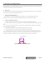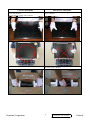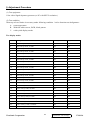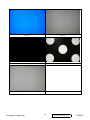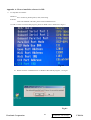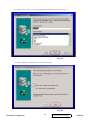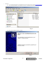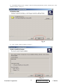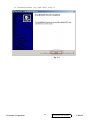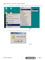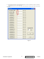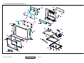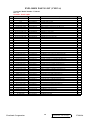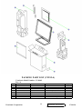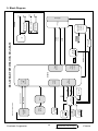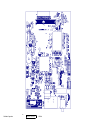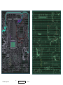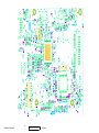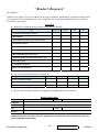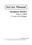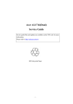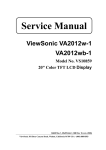
1
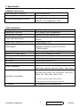
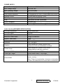
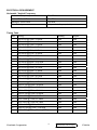
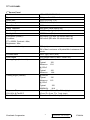
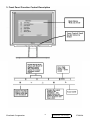
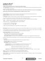
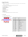
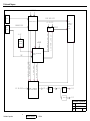
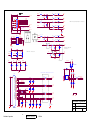
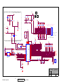
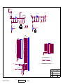
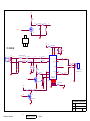
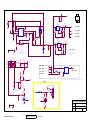
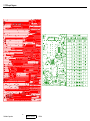
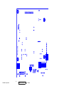
Service Manual
ViewSonic VX912-4
Model No. VS10162
19” Color TFT LCD Display
(VX912-4_SM Rev. 1a Jun. 2006)
ViewSonic 381 Brea Canyon Road, Walnut, California 91789 USA - (800) 888-8583
Copyright
Copyright © 2006 by ViewSonic Corporation. All rights reserved. No part of this publication
may be reproduced, transmitted, transcribed, stored in a retrieval system, or translated into any
language or computer language, in any form or by any means, electronic, mechanical, magnetic,
optical, chemical, manual or otherwise, without the prior written permission of ViewSonic
Corporation.
Disclaimer
ViewSonic makes no representations or warranties, either expressed or implied, with respect to
the contents hereof and specifically disclaims any warranty of merchantability or fitness for any
particular purpose. Further, ViewSonic reserves the right to revise this publication and to make
changes from time to time in the contents hereof without obligation of ViewSonic to notify any
person of such revision or changes.
Trademarks
Opt quest is a registered trademark of ViewSonic Corporation.
ViewSonic is a registered trademark of ViewSonic Corporation.
All other trademarks used within this document are the property of their respective owners.
Revision History
Revision
SM Editing Date
1a
06/07/2006
ViewSonic Corporation
ECR Number
i
Description of Changes
Editor
Initial Release
J. Chang
Confidential - Do Not Copy
VX912-4
TABLE OF CONTENTS
1.Precautions and Safety Notices
1
2.Specification
4
3.Front Panel Function Control Description
9
4.Circuit Description
11
5.Adjustment Procedure
23
6.Troubleshooting Flow Chart
42
7.Recommended Spare Parts List
45
8.Exploded Diagram and Exploded Parts List
47
9.Block Diagram
50
10.Schematic Diagrams
51
11.PCB Layout Diagrams
58
ViewSonic Corporation
ii
Confidential - Do Not Copy
VX912-4
1. Precautions and Safety Notices
1.
Caution :
No modification of any circuit should be attempted . Service work should only be performed after you are thoroughly familiar
with all of the following safety checks and servicing guide line
2.
Safety Check :
Care should be taken while servicing this LCD display. Because of the high voltage used in the inverter circuit. These voltage
are exposed in such areas as the associated transformer circuits .
3.
POWER SUPPLY REQUIREMENTS
The external power converter for this display utilizes AC and DC cords , AC cord is detachable , but DC cord is
permanently attached . Any attempt to replace another adapter could result in serious problem on the display .
4.
LEAKAGE CURRENT HOT CHECK
4-1 Plug the AC cord directly into the AC outlet. Do not use an isolation transformer during this check.
4-2
Connect a 1500 ohm , 10 watt resistor , paralleled by a 0.15uF capacitor between each metallic part and a good earth
ground
4-3 Use an AC voltmeter with 1000 ohm / volt or more sensitivity and measure the AC voltage across the combination
1500 ohm resistor and 0.15uF capacitor.
4-4
Move the resistor connection to each exposed metallic part and measure the voltage.
4-5
Reverse the polarity of the AC plug in the AC outlet and repeat the above measurement.
4-6
Voltage measured must not exceed 1.5 volt RMS, from any exposed metallic part to the ground. A leakage current
tester may be used in the above hot check, in which case any circuit measured must not exceed 1.0 milliamp. In the case of a
measurement exceeding the 1.0 milliamp value, a rework is required to eliminate the chance of a shock hazard .
AC VOLTMETER
V
0.15u
.
To Metal Parts
ViewSonic Corporation
1500
10W
1
Earth Ground
Confidential - Do Not Copy
VX912-4
Correct methods :
Incorrect Methods :
Only touch the metal-frame of the panel or the front
cover of the monitor .
Do not touch the surface of the polarizer .
Surface of the panel is pressed by fingers & this may
cause “ MURA “
Take out the monitor with cushion
Take out the monitor by grasping the LCD panel.
That may cause “ MURA“.
ViewSonic Corporation
2
Confidential - Do Not Copy
VX912-4
Correct Methods :
Incorrect Methods :
Place the monitor on a clean & soft foam pad .
ViewSonic Corporation
Place the monitor on foreign objects .
That could scratch the surface of panel
3
Confidential - Do Not Copy
VX912-4
2. Specification
GENERAL specification
Test Resolution & Frequency
1280x1024 @ 60Hz
Test Image Size
Full Size
Contrast and Brightness Controls
Factory Default:
Contrast = 70%, Brightness = 100%
VIDEO INTERFACE
Analog Input Connector
DB-15 (Analog), refer the appendix A
Digital Input Connector
DVI-I (Digital), refer the appendix B
Default Input Connector
Defaults to the first detected input
Video Cable Strain Relief
Equal to twice the weight of the monitor for five
minutes
Video Cable Connector DB-15 Pin out
Compliant DDC 1/2B
Video Signals
1. Video RGB (Analog)
Separate, Composite, and Sync on Green
2. TMDS (Digital)
Video Impedance
75 Ohms (Analog), 100 Ohms (Digital)
Maximum PC Video Signal
950 mV with no damage to monitor
Maximum Mac Video Signal
1250 mV with no damage to monitor
Sync Signals
LVDS
DDC 1/2B
Compliant with Revision 1.3
Sync Compatibility
Separate Sync, Composite Sync, SOG
Video Compatibility
Shall be compatible with all PC type computers,
Macintosh computers, and after market video cards
Resolution Compatibility
640 x 350*, 640 x 480, 720 x 400* (640 x 400*), 800 x
600, 832 x 624, 1024 x 768, 1152 x 864, 1152 x 870,
1280 x 720, 1280 x 960, 1280 x 1024
* The image vertical size might not be full screen.
But the image vertical position should be at the center.
Exclusions
ViewSonic Corporation
Not compatible with interlaced video
4
Confidential - Do Not Copy
VX912-4
POWER SUPPLY
Internal Power Supply
Part Number: FSP035-1PI01
Input Voltage Range
90 to 264 VAC
Input Frequency Range
47.5 to 63 Hertz
Short Circuit Protection
Output can be shorted without damage
Over Current Protection
3.5 A typical at 12.0 VDC ( Protect when short circuit )
Leakage Current
0.75mA (Max) at 264VAC / 50Hz
Efficiency
77 % typical at 115VAC Full Load
Fuse
Internal and not user replaceable
Power Dissipation
35 Watts (typ)
Max Input AC Current
1.2 Arms @ 90VAC, 0.7 Arms @265VAC
Audio interface(SPEAKER SPECIFICATION)
Line input connection
3.5mm stereo jack
Line input signal
1.3Vrms
Line input impendence
10Kohm
Maximum Power output
1W@<5% distortion
Signal to Noise Ratio
72dB
Frequency response
200Hz – 20K
Distortion
<5% THD @1K
Vibration
There should be no audio vibration with
Volume at 100% and treble/bass at default
Screen image
There should be no affect on the screen
Image stability under any conditions.
Connector PC99 requirement Audio in
Lime Green pantone # 577C
Cable type / length
3.5mm stereo cable / 1.8m length
Audio DPMS
Speakers stay on where the rest of the monitor is in
power –saving.
Note: There us no guarantee <1w power consumption
in active off mode when the Audio cable is connected.
ViewSonic Corporation
5
Confidential - Do Not Copy
VX912-4
ELECTRICAL REQUIREMENT
Horizontal / Vertical Frequency
Horizontal Frequency
30 – 82 kHz
Vertical Refresh Rate
50 – 75 Hz.
Maximum Pixel Clock
135 MHz
Sync Polarity
Independent of sync polarity.
Timing Table
Item
Timing
Analog
Digital
1
640 x 350 @ 70Hz, 31.5kHz
Yes
Yes
2
640 x 400 @ 60Hz, 31.5kHz
Yes
Yes
3
640 x 400 @ 70Hz, 31.5kHz
Yes
Yes
4
640 x 480 @ 50Hz, 24.7kHz
Yes
No
5
640 x 480 @ 60Hz, 31.5kHz
Yes
Yes
6
640 x 480 @ 67Hz, 35.0kHz
Yes
Yes
7
640 x 480 @ 72Hz, 37.9kHz
Yes
Yes
8
640 x 480 @ 75Hz, 37.5kHz
Yes
Yes
9
640 x 480 @ 85Hz, 43.27kHz
Yes
Yes
10
720 x 400 @ 70Hz, 31.5kHz
Yes
Yes
11
800 x 600 @ 56Hz, 35.1kHz
Yes
Yes
12
800 x 600 @ 60Hz, 37.9kHz
Yes
Yes
13
800 x 600 @ 75Hz, 46.9kHz
Yes
Yes
14
800 x 600 @ 72Hz, 48.1kHz
Yes
Yes
15
800 x 600 @ 85Hz, 53.7kHz
Yes
Yes
16
832 x 624 @ 75Hz, 49.7kHz
Yes
Yes
17
1024 x 768 @ 60Hz, 48.4kHz
Yes
Yes
18
1024 x 768 @ 70Hz, 56.5kHz
Yes
Yes
19
1024 x 768 @ 72Hz, 58.1kHz
Yes
Yes
20
1024 x 768 @ 75Hz, 60.0kHz
Yes
Yes
21
1024 x 768 @ 85Hz, 68.67kHz
Yes
Yes
22
1152 x 864 @ 75Hz, 67.5kHz
Yes
Yes
23
1152 x 870 @ 75Hz, 68.7kHz
Yes
Yes
24
1280 x 1024 @ 60Hz, 63.4kHz
Yes
Yes
25
1280 x 1024 @ 75Hz, 79.97kHz
Yes
Yes
26
1280x 720 @ 60Hz, 45kHz (HDTV)
Yes
Yes
ViewSonic Corporation
6
Confidential - Do Not Copy
VX912-4
TFT LCD PANEL
1st Source Panel
Model number
HSD HSD190ME13-D10
Type
TN type with LVDS interface
Active Size
376.3 (H) x 301.1 (V)
Pixel Arrangement
RGB Vertical Stripe
Pixel Pitch
0.294 mm
Glass Treatment
Anti Glare (Hard coating 3H)
# of Backlights
4 CCFL edge-light (2 top / 2 bottom)
Backlight Life
40000 Hours (Min)
Luminance (Center) –
Condition:
CT = 6500K, Contrast = Max,
Brightness = Max
300 cd/m2 (Typ after 30 minute warm up)
240 cd/m2 (Min after 30 minute warm up)
Brightness Uniformity
70% (min)
δW = Max Luminance of 9 points/Min Luminance of 9
points
Contrast Ratio
700:1 (typ), 450:1 (min)
Color Depth
16.2 million colors (6 bits + 2 bits FRC)
Viewing Angle (Horizontal)
@ CR>10
Typical:
Minimum:
@ CR>5
Typical:
Minimum:
Viewing Angle (Vertical)
@ CR>10
Typical:
Minimum:
@ CR>5
Typical:
MINIMUN:
150
130
160
N/A
135
115
150
N/A
Response Time
10%-90% @ Ta=25°C
5 ms (Tr= 1,5 ms, Tf = 3.5 ms) (typ)
10 ms (Tr= 3 ms, Tf = 7 ms) (max)
Panel Defects
Please see Panel Quality Specifications.
ViewSonic Corporation
7
Confidential - Do Not Copy
VX912-4
MECHANICAL
Dimension (Desktop)
Width
431 mm (17 inch)
Height
468 mm (18.4 inch)
Depth
201 mm (7.9 inch)
Monitor Weight
6.7 Kg (14.8 lbs)
Dimension (Head Only / Wall Mount)
Width
431 mm (17 inch)
Height
370 mm (14.6 inch)
Depth
66 mm (2.6 inch)
Monitor Weight
5.3 Kg (11.7 lbs)
Ergonomics
Tilt Up
From 0º up to ≧20º
Tilt Down
From 0º down to -3º ~ -5 º
ENVIRONMENTAL
z Operating Temperature : 0°C to +40°C
z Storage Temperature : -20°C to +60°C
z Operating Relative Humidity : 20% to 90% RH Non-Condensing
z Storage Relative Humidity : 5% to 90% RH Non-Condensing
z Operating Altitude : 0 to +3,000 meters
z Storage Altitude : 0 to +12,000 meters
ViewSonic Corporation
8
Confidential - Do Not Copy
VX912-4
3. Front Panel Function Control Description
ViewSonic Corporation
9
Confidential - Do Not Copy
VX912-4
ViewSonic VX912-4
Main Menu Controls
Adjust the menu items shown below by using the up and down buttons.
Auto Image Adjust automatically sizes, centers, and fine tunes the video signal to eliminate waviness and distortion. Press the
[2] button to obtain a sharper image.
NOTE: Auto Image Adjust works with most common video cards. If this function does not work on your LCD display,
then lower the video refresh rate to 60 Hz and set the resolution to its pre-set value.
Contrast adjusts the difference between the image background (black level) and the foreground (white level).
Brightness adjusts the lamps current to control the screen brightness.
Color Adjust provides several color options: preset color temperatures and Custom User Color which allows you to adjust red
(R), green (G), and blue (B). The factory setting for this product is 6500K (6500° Kelvin).
9300K — Adds blue to the screen image for cooler white (used in most office settings with fluorescent lighting).
5400K — Adds red to the screen image for warmer white and richer red.
Custom User Color — Individual adjustments for red, green, and blue.
1 To select color (R, G or B) press button [2].
2 To adjust selected color, press ▼ or ▲ .
3 When you are finished making all color adjustments, press button [1] twice.
Information displays the timing mode (video signal input) coming from the graphics card in your computer. See your graphic
card’s user guide for instructions on changing the resolution and refresh rate (vertical frequency). VESA 1280 x 1024 @ 60 Hz
(recommended) means that the resolution is 1280 x 1024 and the refresh rate is 60 Hertz.
Manual Image Adjust controls are explained below:
H. Size (Horizontal Size) adjusts the width of the screen image.
NOTE: Vertical size is automatic with your LCD display.
H./V. Position adjusts horizontal and vertical position of the screen image. You can toggle between Horizontal and
Vertical by pressing button [2]. Horizontal moves the screen image to the left or to the right. Vertical moves the screen image
up and down.
Fine Tune sharpens focus by aligning the illuminated text and/or graphic characters.
Sharpness adjusts the clarity and focus of the screen image.
Setup Menu controls are explained below:
Language allows you to choose the language used in the menus and control screens.
Resolution Notice displays the recommended resolution for this LCD display.
Enable allows the Resolution Notice to appear on-screen.
Disable will not allow the Resolution Notice to appear on-screen.
OSD Timeout sets the length of time an on-screen display screen is displayed. For example, with a“15 second”
setting, if a control is not pushed within 15 seconds, the display OSD disappears.
OSD Position allows you to move the on-screen display menus and control screens.
Memory Recall returns adjustments to the original factory settings if the display is operating in a factory Preset Timing Mode
listed in this user guide.
ViewSonic Corporation
10
Confidential - Do Not Copy
VX912-4
4. Circuit Description
1. Outline
3.1. POWER On/Off , LED, Button"2" , Up arrow- button , Down arrow button , Button"1" , button , Down arrow button ,
Button"1" , on the front panel.
3.2. Video signal connector, and AC-IN are located on the back side of the cabinet.
3.3. OSD menu includes the following function;
AUTO IMAGE ADJUST
CONTRAST / BRIGHTNESS
COLOR ADJUST
INFORMATION
MANUAL IMAGE ADJUST
SETUP MENU
MEMORY RECALL
3.4. CONTRAST and BRIGHTNESS can be directly controlled with UP / DN key.
.
2. CONNECTORS
2.1 AC inlet : CEE22 typed connector
1
6
2
7
3
8
4
9
5
10
2.2 Video signal connector 14P + Mini D-Sub
CN6
DB15HD
ViewSonic Corporation
15
14
13
12
17
11
16
PIN
MNEMONI
SIGNAL
1
RV
Red Video
2
GV
Green Video
3
BV
Blue Video
4
NC
None
5
GND
Ground(DDC return)
6
RG
Red GND
7
GG
Green GND
8
BG
Blue GND
9
+5V
+ 5V (for DDC)
10
SG
Sync GND
11
NC
None
12
SDA
DDC Data
13
HS
Horizontal Sync
14
VS
Vertical Sync
15
SCL
DDC Clock
11
Confidential - Do Not Copy
VX912-4
3. ELECTRICAL SPECIFICATIONS
3.1. Standard conditions
Display Area
338 x 270 mm
Video Signal
0.7 Vpp
Contrast
70%
Brightness
Max.
Ambient
20 +/- 5 °C
Input
AC
Warming up
> 30 min
Display
1280 x 1024
3.2. POWER
3.2.1. Power supply
Input Voltage
90 -240 ~Volts
Power Frequency
50/ 60 Hz +/-3Hz
Input current
<1.5Arms @ 90Vac
<0.75Arms@240Vac
Inrush current
90A(max.) at 230Vac
Power consumption
50Watt
Output Voltage
@0-3.0A load 12Vdc
+/-5%
3.2.2. Power Management
State
Power
Indicator
On
40Watt
Green
Standby
<1Watt
Amber
Off
<1Watt
3.3. Acceptable timing
If your timing is within following specification, this LCD display can automatically function with a certain position.
Horizontal: Sync frequency : 30~81 kHz
Vertical: Sync frequency : 56~85Hz(1280x1024,75Hz)
ViewSonic Corporation
12
Confidential - Do Not Copy
VX912-4
3.4. Signal level and input impedance
3.4.1.
Video Signal level This LCD display is adjusted at the factory using 0,7 Vp-p Video signal.
3.4.2.
Sync Signal level
H/V Separate : TTL level
3.4.3.
Input impedance
Video input : 75 ohms
Sync input : > 1 k ohms
4. SIGNAL CABLE : Signal cable with Mini D-Sub 15P connectors at both ends. Length : 1.8 meter.
ViewSonic Corporation
13
Confidential - Do Not Copy
VX912-4
5.
EDID data
Analog EDID
______________________________________________________________________
VIEWSONIC CORPORATION
EDID Version # 1, Revision # 3
DDCTest For: ViewSonic VX912-3
______________________________________________________________________
______________________________________________________________________
128 BYTES OF EDID CODE:
0
1
2
3
4
5
6
7
8
9
________________________________________
0
| 00
FF FF FF FF FF
FF 00 5A 63
10 |
1C D7 01 01 01 01 01 0F 01 03
20 |
0E
30 |
9D 25 17 50 54 BF
40 |
81 40 71 4F 01 01 01 01 01 01
50 |
01 01 01 01 30 2A 00 98 51 00
60 |
2A 40 30 70 13 00 78 2D 11 00
70 |
00 1E 00 00 00 FF 00 50 5A 38
80 |
30 35 30 31 30 30 30 30 31 0A
90 |
00 00 00 FD 00 32 4B 1E 52
100 | 00
26 1E 78 2E 57 45 A4 57
47
EF 80 81 80
0E
0A 20 20 20 20 20 20 00 00
110 | 00 FC 00 56 58 39 31 32 2D 33
120 | 0A 20 20 20 20 20 00 49
______________________________________________________________________
(08-09) ID Manufacturer Name ________________ = VSC
(11-10) Product ID Code _____________________ = D71C
(12-15) Last 5 Digits of Serial Number ______ = Not Used
(16)
Week of Manufacture _________________ = 01
(17)
Year of Manufacture _________________ = 2005
(10-17) Complete Serial Number ______________ = See Descriptor Block
(18)
EDID Version Number _________________ = 1
(19)
EDID Revision Number ________________ = 3
(20)
VIDEO INPUT DEFINITION:
Analog Signal
0.700, 0.300 (1.000 Vp-p)
Separate Syncs, Composite Sync, Sync on Green
(21)
Maximum Horizontal Image Size ________________
= 380 mm
(22)
Maximum Vertical Image Size __________________
= 300 mm
(23)
Display Gamma ________________________________
(24)
Power Management and Supported Feature(s):
Active Off/Very Low Power, Standard Default
ViewSonic Corporation
= 2.20
Color Space,
14
Confidential - Do Not Copy
VX912-4
Preferred Timing Mode
Display Type = R/G/B Color
(25-34) CHROMA INFO:
Red X - 0.642 Green X - 0.278 Blue X - 0.146 White X - 0.313
Red Y - 0.341 Green Y - 0.616 Blue Y - 0.090 White Y - 0.329
(35)
ESTABLISHED TIMING I:
720 X 400 @ 70Hz (IBM,VGA)
640 X 480 @ 60Hz (IBM,VGA)
640 X 480 @ 67Hz (Apple,Mac II)
640 X 480 @ 72Hz (VESA)
640 X 480 @ 75Hz (VESA)
800 X 600 @ 56Hz (VESA)
800 X 600 @ 60Hz (VESA)
(36)
ESTABLISHED TIMING II:
800 X 600 @ 72Hz (VESA)
800 X 600 @ 75Hz (VESA)
832 X 624 @ 75Hz (Apple,Mac II)
1024 X 768 @ 60Hz (VESA)
1024 X 768 @ 70Hz (VESA)
1024 X 768 @ 75Hz (VESA)
1280 X 1024 @ 75Hz (VESA)
(37)
Manufacturer's Reserved Timing:
1152 X 870 @ 75Hz (Apple,Mac II)
(38-53) Standard Timing Identification:
1280 X 1024 @60Hz
1152 X 864 @75Hz
1024 X 768 @85Hz
800 X 600 @85Hz
640 X 480 @85Hz
Not Used
Not Used
Not Used
______________________________________________________________________
(54-71) Detailed Timing / Descriptor Block 1:
1280x1024 Pixel Clock: 108.00 MHz
______________________________________________________________________
ViewSonic Corporation
15
Confidential - Do Not Copy
VX912-4
Horizontal Image Size: 376 mm
Vertical Image Size: 301 mm
Refreshed Mode: Non-Interlaced
Normal Display - No Stereo
Horizontal:
Active Time: 1280 pixels
Blanking Time: 408 pixels
Sync Offset: 48 pixels
Sync Pulse Width: 112 pixels
Border: 0 pixels
Frequency: 63.98 KHz
Active Time: 1024 lines
Blanking Time: 42 lines
Sync Offset: 1 lines
Sync Pulse Width: 3 lines
Vertical:
Border: 0 lines
Frequency: 60.02 Hz
Digital Separate, Horizontal Polarity (+) Vertical Polarity (+)
______________________________________________________________________
(72-89) Detailed Timing / Descriptor Block 2:
Monitor Serial Number:
PZ8050100001
______________________________________________________________________
(90-107) Detailed Timing / Descriptor Block 3:
Monitor Range Limits:
Min Vertical Freq - 50 Hz
Max Vertical Freq - 85 Hz
Min Horiz. Freq - 30 KHz
Max Horiz. Freq - 82 KHz
Pixel Clock - 140 MHz
Secondary GTF - Not Supported
______________________________________________________________________
(108-125) Detailed Timing / Descriptor Block 4:
Monitor Name:
VX912-3
(126)
No Extension EDID Block(s)
(127)
CheckSum OK
ViewSonic Corporation
16
Confidential - Do Not Copy
VX912-4
Digital EDID
______________________________________________________________________
VIEWSONIC CORPORATION
EDID Version # 1, Revision # 3
DDCTest For: ViewSonic VX912
______________________________________________________________________
128 BYTES OF EDID CODE:
0
0
| 00
1
2
3
4
5
6
FF FF FF FF FF
7
8
9
FF 00 5A 63
10 |
1C D7 01 01 01 01 01 0F 01 03
20 |
80 26 1E 78 2E 57 45 A4 57
30 |
9D 25 17 50 54 BF
40 |
81 40 71 4F 31 0A 01 01 01 01
50 |
01 01 01 01 30 2A 00 98 51 00
60 |
2A 40 30 70 13 00 78 2D 11 00
70 |
00 1E 00 00 00 FF 00 50 5A 38
80 |
30 35 30 31 30 30 30 30 31 0A
90 |
00 00 00 FD 00 32 4B 1E 52
100 | 00
47
EF 80 81 80
0E
0A 20 20 20 20 20 20 00 00
110 | 00 FC 00 56 58 39 31 32 2D 33
120 | 0A 20 20 20 20 20 00 49
______________________________________________________________________
(08-09) ID Manufacturer Name ________________ = VSC
(11-10) Product ID Code _____________________ = D71C
(12-15) Last 5 Digits of Serial Number ______ = Not Used
(16)
Week of Manufacture _________________ = 01
(17)
Year of Manufacture _________________ = 2005
(10-17) Complete Serial Number ______________ = See Descriptor Block
(18)
EDID Version Number _________________ = 1
(19)
EDID Revision Number ________________ = 3
(20)
VIDEO INPUT DEFINITION:
Analog Signal
0.700, 0.300 (1.000 Vp-p)
Separate Syncs, Composite Sync, Sync on Green
(21)
Maximum Horizontal Image Size ________________
= 380 mm
(22)
Maximum Vertical Image Size __________________
= 300 mm
(23)
Display Gamma ________________________________
(24)
Power Management and Supported Feature(s):
= 2.20
Active Off/Very Low Power, Standard Default Color Space,
Preferred Timing Mode
Display Type = R/G/B Color
(25-34) CHROMA INFO:
Red X - 0.642 Green X - 0.278 Blue X - 0.146 White X - 0.313
ViewSonic Corporation
17
Confidential - Do Not Copy
VX912-4
Red Y - 0.341 Green Y - 0.616 Blue Y - 0.090 White Y - 0.329
(35)
ESTABLISHED TIMING I:
720 X 400 @ 70Hz (IBM,VGA)
640 X 480 @ 60Hz (IBM,VGA)
640 X 480 @ 67Hz (Apple,Mac II)
640 X 480 @ 72Hz (VESA)
640 X 480 @ 75Hz (VESA)
800 X 600 @ 56Hz (VESA)
800 X 600 @ 60Hz (VESA)
(36)
ESTABLISHED TIMING II:
800 X 600 @ 72Hz (VESA)
800 X 600 @ 75Hz (VESA)
832 X 624 @ 75Hz (Apple,Mac II)
1024 X 768 @ 60Hz (VESA)
1024 X 768 @ 70Hz (VESA)
1024 X 768 @ 75Hz (VESA)
1280 X 1024 @ 75Hz (VESA)
(37)
Manufacturer's Reserved Timing:
1152 X 870 @ 75Hz (Apple,Mac II)
(38-53) Standard Timing Identification:
1280 X 1024 @60Hz
1152 X 864 @75Hz
1024 X 768 @85Hz
800 X 600 @85Hz
640 X 480 @85Hz
Not Used
Not Used
Not Used
______________________________________________________________________
(54-71) Detailed Timing / Descriptor Block 1:
1280x1024 Pixel Clock: 108.00 MHz
______________________________________________________________________
ViewSonic Corporation
18
Confidential - Do Not Copy
VX912-4
Horizontal Image Size: 376 mm
Vertical Image Size: 301 mm
Refreshed Mode: Non-Interlaced
Normal Display - No Stereo
Horizontal:
Active Time: 1280 pixels
Blanking Time: 408 pixels
Sync Offset: 48 pixels
Sync Pulse Width: 112 pixels
Border: 0 pixels
Frequency: 63.98 KHz
Active Time: 1024 lines
Blanking Time: 42 lines
Sync Offset: 1 lines
Sync Pulse Width: 3 lines
Vertical:
Border: 0 lines
Frequency: 60.02 Hz
Digital Separate, Horizontal Polarity (+) Vertical Polarity (+)
______________________________________________________________________
(72-89) Detailed Timing / Descriptor Block 2:
Monitor Serial Number:
PZ8050100001
______________________________________________________________________
(90-107) Detailed Timing / Descriptor Block 3:
Monitor Range Limits:
Min Vertical Freq - 50 Hz
Max Vertical Freq - 85 Hz
Min Horiz. Freq - 30 KHz
Max Horiz. Freq - 82 KHz
Pixel Clock - 140 MHz
Secondary GTF - Not Supported
______________________________________________________________________
(108-125) Detailed Timing / Descriptor Block 4:
Monitor Name:
VX912-3
(126)
No Extension EDID Block(s)
(127)
CheckSum OK
ViewSonic Corporation
19
Confidential - Do Not Copy
VX912-4
6.
THEORY OF OPERATION
This section describes the function of the LCD monitor per functional block.
This monitor includes MB board, power board and button board.
6.1 MB BOARD
The MB board is a two-layer, single-landed design with ground and internal planes provided. DC power from the power
board enter the board through a 6P connector. Other connector on the board is for button board .The VGA cable is a signal
cable that contains video signal, sync signal and DDC signal from PC VGA adapter. This system board consists of 4
functional areas : flat panel controller, MCU with flash ROM , power regulator .
6.1.1
Flat panel controller… MST8131A (U3)
The heart of the system board is MStart MST8131A.
The MST8131A is a graphics processing IC for LCD monitor. It
provides all key IC functions required for LCD panel. On-chip functions include a high-speed triple-ADC , PLL, high
scaling engine, OSD controller.
a) Clock Generation :
Crystal Input Clock (TCLK and XTAL). This is the input pair to an internal crystal oscillator and corresponding logic.
A 14.318 MHz crystal is recommended.
b) Analog to Digital Converter:
The MST8131A chip has three ADC's (analog-to-digital converters), one for each color (red, green and blue) .The
analog RGB signals are connected to MST8131A as described below
Pin Name
Pin Number
Red +
63
Red -
62
Green +
60
Green -
59
Blue +
58
Blue -
57
c). OSD : The MST8131A has a fully programmable ,high-quality OSD controller. The on-chip static RAM(4096
words by 24 bits) stores the cell map and the cell definitions..
d). MTV312 Micro controller: The MTV312 micro controller(MCU) serves as the system micro controller. It’s
programs the MST8131A and manages other devices in the system such as the keypad, the backlight, LED, audio
and non-volatile RAM. using general purpose input/output (GPIO) pins.
ViewSonic Corporation
20
Confidential - Do Not Copy
VX912-4
e).
Pin number
Pin Name
Pin Number Usage
21
P1.3
Key / Power on ,off
13
P3.4
NV_RAM (U4) SDA
14
P3.5
NV_RAM (U4) SCL
25
P1.7
Key_down
9
P6.3
Key_right
24
P1.6
Key_up
16
P6.2
Key_left
37
P4.1
Key_mute
34
P5.6
VGA connector
23
P1.5
Key_select
42
P5.3
LED_red
41
P5.4
LED_green
32
P6.6
LCD panel power1 on / off control
3
P5.0
LCD panel power2 on / off control
36
P4.0
Backlight on / off control
Panel Power Sequencing ( VDDCTRL1, 2) ( Pin 32, 3) : The MTV312 has two dedicated outputs
VDDCTRL1 and 2 ( Pin32 and Pin3)
to control LCD power sequencing once data and control signals
are stable.
f).
Panel interface (Pin 1~25, Pin75~128) : The MTV312 driver interface is highly programmable. It supports
dual bus / dual port for SXGA drivers.
6.1.2 Power Regulator MC34063A (U6),AIC1739 (Q4) : The MC34063A is a monolithic control IC containing the primary
functions required for DC to DC converters. The device consists of an internal temperature compensated reference, comparator,
controlled duty cycle.
Oscillator with an active current sense circuit. Desired output voltage are determined by the equation,
Volt = 1.25 ( 1 + R67 / R66), In this case, the output voltage are 3.3 Volts
The AIC1739 is a low dropout positive adjustable regulator with minimum of 300mA output current capability.
So it is well suited for 3.3 V and 2.5 V Regulator.
6.1.3 Power Regulator MC34063A (U7) : The MC34063A is a monolithic control IC containing the primary functions required
for DC to DC converters. The device consists of an internal temperature compensated reference, comparator, controlled duty
cycle.
Oscillator with an active current sense circuit. Desired output voltage are determined by the equation,
Volt = 1.25 ( 1 + R85 / R86), In this case, the output voltage are 5.0 Volts for panel power.
ViewSonic Corporation
21
Confidential - Do Not Copy
VX912-4
6.3 Power(Inverter) Board
This is a specific power(inverter) power board for VE912 monitor 40W 12V 3.5A output power and backlight which
converters 12 Vdc to drive four cold cathode fluorescence tubes.
6.3.1 Inverter Electrical specification described as below.
Input
Output
Rated Input Voltage
12Vdc
Input Voltage Range
11.4 ~ 12.6 Vdc
Input Current
<2A
On / Off control Voltage
2~3.3 for on , 0~1 for off
Rated Output Strike-on Voltage
1500Vrms
Rated Output Voltage
912Vrms at 7mA
Rate Output Frequency
40~50KHz
Rated Ourput Current
7~8 mA
6.3.2 power
This is a general purpose AC / DC adapter which converter 90~240 Vac to a stabilized DC voltage 12 V with rated output
current of 4.16A . Electrical specification described as below.
Rated Input Voltage
90~240 Vac , 50 / 60Hz
Operation Input Voltage
90~260 Vac , 47 ~ 63Hz
Input Current
<1.5A
Inrush Current
<100A@120Vac
Standby Input Voltage
12Vdc
Output Voltage Regulation
+/-5%
Output Ripple & Noise
120mVp-p
Rate Output Current
<3.5A
Turn-on delay
<3secs
ViewSonic Corporation
22
Confidential - Do Not Copy
VX912-4
5. Adjustment Procedure
Function test
(1) Test equipment
Color video Signal & pattern generator (or PC with SXGV resolution )
(2) Test condition
Warm-up at least 30mins is necessary under following condition
A. room temperature
B. With full-white screen , RGB , black pattern
C. with cycled display modes.
before function test & alignment :
Test display modes
Item
Timing
Analog
Digital
1
640 x 350 @ 70Hz, 31.5kHz
Yes
Yes
2
640 x 400 @ 60Hz, 31.5kHz
Yes
Yes
3
640 x 400 @ 70Hz, 31.5kHz
Yes
Yes
4
640 x 480 @ 60Hz, 31.5kHz
Yes
Yes
5
640 x 480 @ 67Hz, 35.0kHz
Yes
Yes
6
640 x 480 @ 72Hz, 37.9kHz
Yes
Yes
7
640 x 480 @ 75Hz, 37.5kHz
Yes
Yes
8
640 x 480 @ 85Hz, 43.27kHz
Yes
Yes
9
720 x 400 @ 70Hz, 31.5kHz
Yes
Yes
10
800 x 600 @ 56Hz, 35.1kHz
Yes
Yes
11
800 x 600 @ 60Hz, 37.9kHz
Yes
Yes
12
800 x 600 @ 75Hz, 46.9kHz
Yes
Yes
13
800 x 600 @ 72Hz, 48.1kHz
Yes
Yes
14
800 x 600 @ 85Hz, 53.7kHz
Yes
Yes
15
832 x 624 @ 75Hz, 49.7kHz
Yes
Yes
16
1024 x 768 @ 60Hz, 48.4kHz
Yes
Yes
17
1024 x 768 @ 70Hz, 56.5kHz
Yes
Yes
18
1024 x 768 @ 72Hz, 58.1kHz
Yes
Yes
19
1024 x 768 @ 75Hz, 60.0kHz
Yes
Yes
20
1024 x 768 @ 85Hz, 68.67kHz
Yes
Yes
21
1152 x 864 @ 75Hz, 67.5kHz
Yes
Yes
22
1152 x 870 @ 75Hz, 68.7kHz
Yes
Yes
23
1280 x 1024 @ 60Hz, 63.4kHz
Yes
Yes
24
1280 x 1024 @ 75Hz, 79.97kHz
Yes
Yes
25
1280x 720 @ 60Hz, 45kHz (HDTV)
Yes
Yes
ViewSonic Corporation
23
Confidential - Do Not Copy
VX912-4
Test pattern
Item Test condition
Pattern
Specification
Remark
1
Frequency &
performance
Cross-hatch
pattern
No noise is allow & all color
is clear
Pattern 1
2
Monitor saturation
16-gray scale
pattern
3~4 level need to saturated
when brightness & contrast is
100%
Pattern 2
3
RGB color
performance
RGB color
Check the color temperature
of RGB signal color
Pattern 3, 4, 5
4
Sub-pixel defect
RGB color
Check the sub-pixel defect
Pattern 3, 4 , 5
5
Full white
Full white
Check the brightness
bright pixel defect
Pattern 6
6
Full black
Full black
7.
5-cycle pattern
5-cycle pattern
Check the BU
Pattern 8
8.
1-dot pattern
1-dot pattern
Check the flicker
Pattern 9
,CR &
Pattern 7
Pattern 1
Pattern2
Pattern 3
Pattern4
ViewSonic Corporation
24
Confidential - Do Not Copy
VX912-4
Pattern 5
Pattern6
Pattern 7
Pattern 8
Pattern 9
ViewSonic Corporation
25
Confidential - Do Not Copy
VX912-4
Firmware update procedure :
When you received a received monitor , please check whether the firmware version.
procedure to upgrade to the latest version .
If not , please following
1. Equipment needed :
- VX912-4
- PC ( Personal computer )
- LPT cable
- Fixture (for LM5ISP)
- Firmware upgrade program
-
2.
Connection :
To monitor
To PC
ViewSonic Corporation
26
Confidential - Do Not Copy
VX912-4
Appendix A : How to install the software for ISP :
0.
To setup ISP environment :
Hardware:
PC or notebook, parallel(printer) cable, ISP tooling.
Software:
If OS was Win2000 or WinXP , please install “PORT95NT.exe”
In order to ensure can execute ISP program, please set BIOS in PC or Notebook as Fig 0.0
Fig 0.0
0.1 Double-click the “ PORT95NT.exe” in Windows & install the program. , see Fig 0.1
Fig 0.1
ViewSonic Corporation
27
Confidential - Do Not Copy
VX912-4
0.2 Keep on press “ Next “ 4 times to go through the installation processes, see Fig. 0.2
Fig. 0.2
0.3 Choose “ Typical “ then press “ Next “ , see Fig. 0.3
Fig. 0.3
ViewSonic Corporation
28
Confidential - Do Not Copy
VX912-4
0.4 Keep on press “ Next “ 4 times to go through the installation processes, see Fig. 0.4
Fig. 0.4
0.5 Install completed , restart the PC or notebook. See Fig 0.5
Fig. 0.5
ViewSonic Corporation
29
Confidential - Do Not Copy
VX912-4
1.
Install ISP
1.1 User could download ISP driver and PORT95NT install from Myson Century website (www.myson.com.tw)
1.2 After extracting the ZIP file , the total files list as Fig 1.0 , and double click the file of setup.exe to install.
Fig 1.0
1.3
Press “ Next “ button to continue., see Fig 1.1
Fig 1.1
ViewSonic Corporation
30
Confidential - Do Not Copy
VX912-4
1.4 Keep default setting or press “ Change “ button for selecting the path that you want , and then press “ Next
“ button to continue , see Fig 1.2
Fig 1.2
1.5
Press “ Install “ button to continue , see Fig 1.3
Fig. 1.3
ViewSonic Corporation
31
Confidential - Do Not Copy
VX912-4
1.6
Installation has finished , press “ Finish “ button , see Fig 1.4
Fig. 1.4
ViewSonic Corporation
32
Confidential - Do Not Copy
VX912-4
Appendix B : How to use software to upgrade the BIOS :
2.1 After installation , we could find the shortcut in the setting path or the program bar ( default setting ) , see Fig 2.1
Fig. 2.1
2.2 Security file is a key to use ISP function , press “ OK “ button , see Fig 2.2
Fig. 2.2
ViewSonic Corporation
33
Confidential - Do Not Copy
VX912-4
2.3 The warning is used to remind user of that different CPU rate may cause ISP function fail. (it’s limited by IIC
protocol ) , press “ OK “ button , see Fig 2.3
Fig. 2.3
2.4 Press “ Create Security File “ button to key in Security code . Adjusting bar to decrease speed of IIC bus , See
Fig. 2.4 .
Speed of IIC bus
Fig. 2.4
ViewSonic Corporation
34
Confidential - Do Not Copy
VX912-4
2.5 Fig 2.5 shows the setting for security code of software ISP . it needs 2 command No. and key in command
sequentially for 7C , 4C , 77. The command No.
and command must be set by user while coding. About the detailed of setting , please refer to section 6 boot
code of ISP .
Fig. 2.5
ViewSonic Corporation
35
Confidential - Do Not Copy
VX912-4
Appendix C : Use ISP to program MCU
3.1 Select MTV type first , load the binary or intel hex file that you want to program into the MCU , and select
“ AUTO” item , then press “ RUN “ button , see fig3.1
Step 2
Step 1
Step 3
Step 4
Fig. 3.1
3.2 If user change the MTV type , it must load file again , or the buffer of load file will be cleared .
3.3 CRC ( cyclic redundancy check ) : the host can check CRC register’s result instead of reading every byte in
flash .
ViewSonic Corporation
36
Confidential - Do Not Copy
VX912-4
The message of Check MCU CRC OK means that the host verify OK for the progress of program , see Fig.3.2
Fig. 3.2
ViewSonic Corporation
37
Confidential - Do Not Copy
VX912-4
1. Packing procedure
1.1
Paste protection film to protect the monitor (Figure.1)
1.2
Put the monitor in EPE bag & seal the with tape . (Figure.2)
Figure.1
Figure.2
1.3 Put the cushion on the monitor (Figure.3)
1.4 Put the monitor into carton & put all the accessories into the carton .Then close the carton . (Figure.4)
(Figure 3)
(Figure 4)
QSG
ViewSonic Corporation
38
Power cord
Confidential - Do Not Copy
VX912-4
2. Disassemble monitor
2.1 Turn the monitor , face to back-side & take the I/O cover off. (Figure 5)
2.2 Remove the stand back cover (Figure 6)
(Figure 5)
(Figure 6)
2.3 Remove the 4pcs of black hinge screw & separate the stand & head part (Figure 7)
2.4 Face-down & put the monitor on soft surface of desktop (Figure 8)
Figure 7
Figure 8
Screws
ViewSonic Corporation
39
Screws
Confidential - Do Not Copy
VX912-4
2.5 Remove the 4 black screw on 4 corners .& separate the cover & front-bezel (Figure 9)
2.6 Remove the screws which for fixed the B/B & pull the cable out from the connector on M/B (Figure 10)
Figure 9
Figure 10
2.7 Remove the B/B (Figure 11)
2.8 Remove the screws on PCB shield & remove it . (Figure 12)
Figure 11
Figure 12
Screws
ViewSonic Corporation
40
Confidential - Do Not Copy
VX912-4
2.9 Remove the MB-LCD connector & loosen the 4 screws on PCB holder . (Figure 13)
2.10 Separate the PCB holder & panel . (Figure 14)
Figure 13
Figure 14
Screws
2.11 Loosen the 4 screws on the sides of panel (Figure 15)
2.12 Remove the front bezel & panel (Figure 16)
Figure 15
Figure 16
2.13 Remove the 4 hexagon screws beside the DVI & D-sub connector . (Figure 17)
2.14 Remove the screws which fixed the power board & Mainboard (Figure 18)
Figure 17
ViewSonic Corporation
Figure 18
41
Confidential - Do Not Copy
VX912-4
6. Troubleshooting Flow Chart
No Power
ViewSonic Corporation
42
Confidential - Do Not Copy
VX912-4
No Characters , Missing Color
ViewSonic Corporation
43
Confidential - Do Not Copy
VX912-4
Always show NO SIGNEL
ViewSonic Corporation
44
Confidential - Do Not Copy
VX912-4
7. Recommended Spare Parts List
RECOMMENDED SPARE PARTS LIST (VX912-4)
Item
1
2
3
4
5
6
7
8
9
10
11
12
13
14
15
16
17
18
19
20
21
22
23
24
25
26
ViewSonic Model Number: VS10162
Rev: 1A
Serial No. Prefix: Q8D
Description
Board Assembly:
Cabinets:
Cables:
Electronic
Components:
Hardware:
Miscellaneous:
Documentation:
Packing Material:
ECR/ECN
ViewSonic P/N
Universal Number#
Ref. P/N
Location
power board ADP/INV,FSP043-2PI01 90~264V
B-00003993
AS05B312D00
power board
Qt'y
1
main board - L9TA M/B ASSY(RTD2523-LF)
B-00005431
1SL9V0MB041
main board
1
button board L7VD
B-00005207
1SL9V0BB003
button board
1
STAND COVER (EBL9V002,REV3A
C-00001778
EBL9V002015
STAND COVER
1
Base Ass'y Stand SUB ASSY L9VDQ-4 GP
C-00005372
37L9V0SU002
stand
1
front bezel assembly L9VDQ-1A SUB ASSY GP
C-00005432
34L9V0LB018
front bezel assembly
1
back cover assembly
C-00005376
35L9V0LS009
back cover assembly
1
VGA cable (15/15P,1.8M)L7VD
CB-00002602
DDL7VDPC005
VGA cable
1
DVI cable L0T MB-DVI(24P,REV2A) GP
CB-00003440
DD0L0TTH108
DVI cable
1
MB-LCD cable (30P,140MM,LINKTEC,AU)L9VA
CB-00004152
DD0L9VLC023
MB-LCD cable
1
audio cable (ST,1.8M)BLACK W9ZA) GP
CB-00005211
DDW9ZAPA009
audio cable
1
cable Button-MB (10P/8P,240MM)W0E
CB-00005371
DD0W0ETH002
cable Button-MB
1
E-00005213
DN0TE230F06
speaker assembly
1
speaker assembly L9VDQ FG-TE230
LCD panel 19" HSD190ME13-D10 5MS
E-00005370
AA90ME130F5
LCD panel
1
HW-00005216
3FL9V0HS002
hinge cover
1
panel to L/R bracket SCREW M3.0*6.0-I(NI)
M-SCW-0824-6800
MM30060IBJ8
panel to L/R bracket
4
PCBAs to metal shielding SCREW F3.0*6-B(NI)
M-SCW-0824-0813
MF30060BBJ6
PCBAs to metal shielding
7
hinge cover
DVI&D-SUB to shielding IO NUT LI1(MBLI1004
M-MS-0808-8986
MBLI1004018
DVI&D-SUB to shielding
4
LCD FILM L9V(JXL9V001
M-MS-0808-9682
JXL9V001010
LCD film
1
rubber plug VESA L9V(GAL9V002
M-MS-0808-9815
GAL9V002014
rubber plug
4
user guide (VX912-4) L9VD-H(HGL9V023,R3A)
DC-00005433
HGL9V023017
user guide
1
5MS sticker VX912-4 L9VD-H(HCL9V022,REV3A
DC-00005434
HCL9V022017
5MS sticker
1
P-00001432
HFL9V005018
carton
1
cushion END CAP-R L9V(HBL9V002,REV3A)
P-FM-0602-0896
HBL9V001019
cushion
1
cushion END CAP-L L9V(HBL9V001,REV3A
P-FM-0602-0897
HBL9V002015
cushion
1
EPE bag
M-MS-0808-9817
HAL9V002014
EPE bag
1
carton VX912 L9VD(HFL9V005,REV3A
M-Model (VX912-4M)
Item
1 Accessories:
Power Cord 3P 1.8M(USA)V04VS350012180
P-Model (VX912-4P)
Item
1 Accessories:
POWER CORD SP-305+IS-14 3P 1.8M(TWN)B
G-Model (VX912-4G)
Item
1 Accessories:
2 Documentation:
3
4
5
Description
Power Cord
Qc-Pass Label
VSCN Warranty Card
Warranty Sticker
Address Label
E-Model (VX912-4E)
Item
1 Accessories:
Power Cord SP-023+IS-14 1.8M(B)EU
Description
Description
Description
PWR CORD SP-60+IS-14H05VV-F 3P 1.8
ECR/ECN
ECR/ECN
ECR/ECN
ECR/ECN
ViewSonic P/N
A-PC-0106-0224
Ref. P/N
DM333181G97
Location
power cord
Universal Number#
ViewSonic P/N
A-00003642
Ref. P/N
DM33T181004
Location
power cord
Universal Number#
ViewSonic P/N
A-PC-0106-0306
DC-00003444
DC-00003445
M-00003446
DC-00003443
Ref. P/N
DM333181S01
HCL7V026017
HDL7V005011
HCL7V023018
HCL7V024014
Location
power cord
Qc-Pass Label
Warranty Card
Warranty Sticker
Address Label
Universal Number#
ViewSonic P/N
A-PC-0106-0227
Ref. P/N
DM333181801
Universal Number#
A-00003644
DM333181703
Location
power cord
power cord
Qt'y
1
Qt'y
1
Qt'y
1
1
1
1
1
Qt'y
1
1
Remark 1: Above listed items are examples, supplier can expand the rows to add more necessary items.
Remark 2: All revised RSPLs with newly added items or any change made should be highlighted and correlated with the ECN/ECR approved by ViewSonic Corporation.
This is to eliminate repeated cross checks of each item between this version and prior versions.
ViewSonic Corporation
45
Confidential - Do Not Copy
VX912-4
ViewSonic Model Number: VS10162
Rev: 1a
Serial No. Prefix: Q8D
Item
1
2
3
4
5
6
7
8
9
10
11
12
13
14
15
16
17
18
19
20
21
22
23
24
25
26
27
28
29
30
31
32
33
34
35
36
37
38
39
40
41
42
43
44
45
46
47
48
49
50
51
52
53
54
55
56
57
58
59
60
61
62
63
64
65
66
67
68
69
70
71
72
73
74
75
76
77
78
79
80
81
82
83
84
85
86
87
88
89
90
91
92
93
ViewSonic P/N
N/A
B-00004169
N/A
N/A
N/A
N/A
N/A
N/A
B-00003993
N/A
N/A
N/A
N/A
N/A
C-00005432
N/A
N/A
N/A
M-MS-0808-9401
M-MS-0808-9243
M-MS-0808-9402
N/A
N/A
M-SCW-0824-6802
M-SCW-0824-0813
M-SCW-0824-0726
M-SCW-0824-6799
M-MS-0808-8986
N/A
PL-00001806
CB-00002525
CB-00004152
CB-00005371
E-00005213
N/A
N/A
N/A
M-MS-0808-9248
N/A
N/A
N/A
N/A
C-00005376
N/A
M-MS-0808-9253
M-MS-0808-9411
N/A
M-SCW-0824-6895
N/A
C-00005372
N/A
N/A
C-BS-0303-0553
M-CV-0830-2589
M-MS-0808-9811
N/A
M-SCW-0824-0813
N/A
M-MS-0808-9812
N/A
E-00005370
N/A
HW-00001807
M-SCW-0824-6800
N/A
HW-00005216
C-00001778
M-CV-0830-2593
M-MS-0808-9815
M-SCW-0824-6859
M-SCW-0824-0795
M-SCW-0824-6894
N/A
CB-00002602
CB-00003440
CB-00005211
PL-00005198
P-FM-0602-0897
P-FM-0602-0896
M-MS-0808-9817
M-LB-0813-0747
N/A
M-LB-0813-0745
P-00001432
DC-00005433
M-MS-0808-9682
M-LB-0813-1043
N/A
DC-00005434
N/A
N/A
N/A
A-PC-0106-0224
Ref. P/N
1L9VZHXVS40
21L9TAMB090
31L9TASS079
23L7VDBB001
DFHD08MR319
BEYG0014DA0
DAL7VDTB113
DHP0002B205
AS05B312D00
24L9V0LB042
36L9V0PS006
FAL9V004017
FCL9V001010
FCL9V003012
34L9V0LB018
EAL9V009019
EAL9V006010
EBL9V004018
EBL7V028019
FEL7V003019
FEL7V007014
FBL9V011014
FCL9V002016
MM30040IBJ9
MF30060BBJ6
MF30080BBJ5
MM35080BBW2
MBLI1004018
GAL5T002012
GAL5T001016
DD0L9VLC015
DD0L9VLC023
DD0W0ETH002
DN0TE230F06
FCL9V005015
FCM7T004014
FCL7G001016
FCL7A001014
FCL9ZA01019
FCL7C004011
GAL7TA02012
25L9V0LC007
35L9V0LS009
EAL9V008012
FEL7V005011
FBL70008014
FAL9V003011
MF40080IBJ1
26L9V0SA008
37L9V0SU002
FAL9V006010
FAL9V005013
EAL9V004017
EAL9V005013
GAL5M002011
MM40060BCI6
MF30060BBJ6
FCL9V004019
EBL9V001019
2AL9V0PTU08
AA90ME130F5
AZL9VDBU006
FBL9V009010
MM30060IBJ8
27L9V0CS014
3FL9V0HS002
EBL9V002015
EBL9V003011
GAL9V002014
MM40060IL69
MM40080BCI5
MF30060BJ28
28L9V0PK0A1
DDL7VDPC005
DD0L0TTH108
DDW9ZAPA009
JXLM5003011
HBL9V002015
HBL9V001019
HAL9V002014
HCL7V004013
HCL9V014014
HCL7V002011
HFL9V005018
HGL9V023017
JXL9V001010
HCL70021011
HFL9V002019
HCL9V022017
HCL5VC02019
HCL9VA02011
HDL7VC02015
DM333181G97
ViewSonic Corporation
BOM LIST (VX912-4)
Description
L9V LCD MONITOR(L9VD-H,VX912-4)USA GP
L9TA M/B ASSY(RTD2523-LF) GP
L9TA M/B S/S ASSY(RTD2523-LF) GP
L7VD BUTTON/B ASSY GP
CONN DIP HEADER 8P 1R MR(P2.0,H4.1) GP
LED(DIP) YELLOW/GREEN(L-3WYGW-F01) GP
PCB(BUTTON) L7VD TL(1L,180*15,REVA) GP
SWITCH PUCH BUTTON(PT-002-B2,50MA,12V)GP
ADP/INV,FSP043-2PI01 90~264V REV:D GP
L9VD-H LCD BEZEL ASSY GP
L9VDQ-1A PCB SHIELDING ASSY SPK GP
PCB SHDING L9VDQ-4(FAL9V004,R3A)SPK GP
SHIELDING MYLAR L9VDQ-4(FCL9V001,R3A)GP
I/O MYLAR L9VDQ-4(FCL9V003,REV3A) GP
L9VDQ-1A LCD BEZEL SUB ASSY GP
LCD BEZEL(SPK) L9VDQ-1A(EAL9V009,R3A) GP
LCD MASK L9VDQ-4(EAL9V006,REV3A) GP
CONTROL BUTTON L9VDQ-4(EBL9V004,R3A) GP
LENS L7VD(EBL7V028,REV3A)GP
LOGO FRONT-VSC-38MM L7VC(REV3A)GP
BIRD LOGO L7VD(FEL7V007,REV3A)GP
LCD PANEL LOCK METAL L9VDQ(R3A)GP
POWER MYLAR L9VDQ-4(FCL9V002,REV3A) GP
SCREW M3.0*4.0-I(NI) GP
SCREW F3.0*6-B(NI)GP
SCREW F3.0*8L,B,NI GP
SCREW M3.5*8-B (NI,WASHER)GP
IO NUT LI1(MBLI1004,REV3A)GP
RUBBER-HOLDER L5TL-N(GAL5T002,REV3B)GP
RUBBER-HOLDER L5TL-E(GAL5T001,REV3B)GP
CABLE MB-LCD(30P,140MM)L9V-5 GP
CABLE LVDS(30P,140MM,LINKTEC,AU)L9VA GP
CABLE MB-BUTTON(10P/8P,240MM)W0E GP
SPEAKER ASSY L9VDQ FG-TE230 GP
AL FOIL L9VDQ-4(FCL9V005,R3A)100*80 GP
AL FOIL M7T(FCM7T004,REV3A) GP
AL FOIL L7G(FCL7G001,REV3A)HAN GP
AL FOIL L7A(FCL7A001,REV3A) GP
MYLAR L9ZA(FCL9ZA01,REV3A)GP
PANEL MYLAR LEFT L7C(FCL7C004,REV3A)GP
RUBBER-10*20*6.8 L7TA(GAL7TA02,R3A)GP
L9VDQ-4 LCD COVER ASSY GP
L9VDQ-4 LCD COVER SUB ASSY GP
LCD COVER L9VDQ-4(EAL9V008,REV3B) GP
LOGO PLATE ELLIPSE L7VC(REV3A)GP
LOCK METAL L70B(FBL70008,REV3A) GP
HINGE BKT L9VDQ-4(FAL9V003,REV3A) GP
SCREW F4.0*8-I(NI)GP
L9VDQ-4 STAND ASSY GP
L9VDQ-4 STAND SUB ASSY GP
STAND BASE L9VDQ-4(FAL9V006,REV3A) GP
HINGE L9VDQ-4(FAL9V005,REV3A) GP
STAND BASE L9V(EAL9V004,REV3A)GP
STAND BKT COVER L9V(EAL9V005,REV3A)GP
RUBBER FOOT L5M(GAL5M002,REV3B)GP
SCREW M4.0* 6-B(NI,NYLOK) GP
SCREW F3.0*6-B(NI)GP
STAND EVA L9VDQ-4(FCL9V004,REV3A) GP
STAND COVER F L9V(EBL9V001,REV3A)GP
L9VD-H(VX912-4) PANEL KIT ASSY(HSD) GP
LCD(TFT)19" HSD190ME13-D10 5MS GP
L9VD-H(VX912-4) SW BIOS IMAGE 2523(HSD)
LCD BKT L-R L9VD-1(FBL9V009,REV3B)GP
SCREW M3.0*6.0-I(NI) GP
L9VDQ-1A CHASSIS ASSY GP
L9VDQ-4 HINGE COVER SUB ASSY GP
STAND COVER R L9V(EBL9V002,REV3A)GP
I/O COVER L9V(EBL9V003,REV3B)GP
RUBBER PLUG VESA L9V(GAL9V002,REV3A)GP
SCREW M4*6-I (BNI)(NYLOK))GP
SCREW M4.0*8-B(NI,NYLOK)GP
SCREW F3.0*6-B(BNI)GP
L9VD-H PACKING ASSY(VX912-4) GP
CABLE MB-VGA (15/15P,1.8M)L7VD GP
CABLE DVI L0T BLACK 1800(24P) GP
CABLE AUDIO(ST,1.8M)BLACK W9ZA GP
HANDLE LM5S(JXLM5003,REV 3B) GP
END CAP-R L9V(HBL9V002,REV3A)GP
END CAP-L L9V(HBL9V001,REV3A)GP
EPE BAG L9VD(HAL9V002,REV3A)GP
CORE LABEL(HCL7V004,REV3A)GP
ID LABEL VX912 L9VDQ-1A(HCL9V014,R3A)GP
SERIAL LEBAL L7V(HCL7V002,REV3A) GP
CARTON VX912 L9VD(HFL9V005,REV3A)GP
CD+QSG(VX912-4) L9VD-H(HGL9V023,R3A)GP
LCD FILM L9V(JXL9V001,REV3A) GP
HI-POT LABEL L70L(HCL70021,REV3A)GP
SPACE PLATE L9V(HFL9V002,REV3A)GP
5MS VX912-4 L9VD-H(HCL9V022,REV3A) GP
ROHS LABEL(W) 27*27 L5VC(HCL5VC02,R3A)GP
CARTON LABEL(4) L9VA(HCL9VA02,R3A) GP
(B)17-19"SERV.PAPER L7VC(HDL7VC02,R3A)GP
POWER CORD SP-30+IS-14 3P 1.8M(USA)B GP
46
Location
Universal number#
CN1
LED1
SW1,SW2,SW3,SW4,SW5
Confidential - Do Not Copy
Q'ty
1
1
1
1
1
1
5
1
1
1
1
1
1
1
1
1
1
1
1
1
2
1
8
5
4
1
4
4
2
1
1
1
1
1
3
1
1
2
2
2
1
1
1
1
1
1
4
1
1
1
1
1
1
4
4
11
2
1
1
1
1
2
4
1
1
1
1
4
4
4
2
1
1
1
1
1
1
1
1
1
1
1
1
1
1
1
0.05
1
1
1
1
1
VX912-4
8. Exploded Diagram and Exploded Parts List
ViewSonic Corporation
47
Confidential - Do Not Copy
VX912-4
EXPLODED PARTS LIST (VX912-4)
ViewSonic Model Number: VS10162
Rev: 1a
Serial No. Prefix: Q8D
Item
1
2
3
4
5
6
7
8
9
10
11
12
13
14
15
16
17
18
19
20
21
22
23
24
25
26
27
28
29
30
31
32
33
34
35
36
37
38
39
40
41
42
43
44
45
46
ViewSonic P/N
N/A
N/A
N/A
M-MS-0808-9243
M-MS-0808-9401
M-MS-0808-9402
N/A
N/A
M-SCW-0824-0726
E-00005370
HW-00001807
M-SCW-0824-6802
M-BK-0805-0079
CB-00002525
B-00003993
B-00004169
CB-00005371
M-SCW-0824-6799
M-SCW-0824-6800
M-MS-0808-9405
HW-00000989
M-MS-0808-9811
M-SCW-0824-0813
M-CV-0830-2589
M-MS-0808-9812
M-BK-0805-0110
C-BS-0303-0553
M-MS-0808-9813
M-SCW-0824-6859
M-SCW-0824-6894
M-MS-0808-9404
C-00001778
M-SCW-0824-6895
M-BK-0805-0111
M-CV-0830-2590
M-CV-0830-2591
M-MS-0808-9411
N/A
M-SCW-0824-6859
M-CV-0830-2593
M-MS-0808-9253
M-SCW-0824-0870
M-MS-0808-9815
PL-00001804
PL-00001805
PL-00001806
ViewSonic Corporation
Ref. P/N
EAL9V009019
EAL9V006010
EBL9V004018
FEL7V003019
EBL7V028019
FEL7V007014
23L7VDBB006
FBL9V011014
MF30080BBJ5
AA90ME130F5
FBL9V009010
MM30040IBJ9
FAL7V014017
DD0L9VLC015
AS05B312D00
21L9TAMB090
DD0W0ETH002
MM35080BBW2
MM30060IBJ8
FAL7V015013
MM30040IBJ8
GAL5M002011
MF30060BBJ6
EAL9V005013
EBL9V001019
FBL9V005014
EAL9V004017
FBL9V006011
MM40060IL69
MF30060BJ28
EBL7V029015
EBL9V002015
MF40080IBJ1
FBL9V002015
FBL9V001019
FBL9V003011
FBL70008014
EAL9V008012
MM40060IL69
EBL9V003011
FEL7V005011
MS40070B808
GAL9V002014
GAL70002015
GAL70005014
GAL5T001016
Description
BEZEL L9V
MIDDLE BEZEL L9V
CONTROL BUTTON
LOGO FRONT-VSC-38CM L7VC(FEL7V003,REV3A)
LENS L7VD(EBL7V028,REV3A)
BIRD LOGO L7VD(FEL7V007,REV3A)
BUTTON/B ASSY
LCD PANEL LOCK METAL L9V
SCREW F3.0*8L,B,NI
LCD(TFT)19" HSD190ME13-D10 5MS GP
LCD BKT L9V(FBL9V004,REV3A)
SCREW M3.0*4.0-I(NI) GP
PCB BKT L7VD(FAL7V014,REV3A)
CABLE MB-LCDL9V-5 GP
ADP/INV,FSP043-2PI01 90~264V GP
L9TA M/B ASSY(RTD2523-LF) GP
CABLE ASSY L7VD BUTTON-MB (8P-10P)
SCREW M3.5*8-B (NI,WASHER)
SCREW M3.0*6.0-I(NI)
PCB SHIELDING L7VD(FAL7V015,REV3A)
SCREW M3.0*4.0-I(NI)
RUBBER FOOT L5M(GAL5M002,REV3B)
SCREW F3.0*6-B(NI)
STAND BKT COVER L9V(EAL9V005,REV3A)
STAND COVER F L9V(EBL9V001,REV3A)
STAND BKT L9V(FBL9V005,REV3A)
STAND BASE L9V(EAL9V004,REV3A)
STAND PLATE L9V(FBL9V006,REV3A)
SCREW M4*6-I (BNI)(NYLOK))
SCREW F3.0*6-B(BNI)
WIRE CLAMP L7VD(EBL7V029,REV3A)
STAND COVER R L9V(EBL9V002,REV3A)
SCREW F4.0*8-I(NI)
HNGE-BKT L9V(FBL9V002,REV3A)
HINGE-L L9V(FBL9V001,REV3A)
HINGE-R L9V(FBL9V003,REV3A)
LOCK METAL L70B(FBL70008,REV3A)
LCD COVER L9V(EAL9V008,REV3A)
SCREW M4.0x6 (BNI)NYLOCK
I/O COVER L9V(EBL9V003,REV3A)
LOGO PLATE
SCREW M4.0x7 (BMC)NYLOCK
RUBBER PLUG VESA L9V
RUBBER HOLDER
RUBBER BKT
RUBBER HOLDER
48
Confidential - Do Not Copy
Q'ty
1
1
1
1
1
1
1
2
2
1
2
4
1
1
1
1
1
1
7
1
10
4
1
1
1
4
1
1
4
4
2
1
8
1
1
1
1
1
6
1
1
4
4
2
2
4
VX912-4
PACKING PART LIST (VX912-4)
Item
1
2
3
4
5
6
7
8
ViewSonic Model Number: VS10162
Rev: 1a
ViewSonic P/N
N/A
P-FM-0602-0896
P-FM-0602-0897
DC-00005433
A-PC-0106-0227
P-00001432
M-LB-0813-1042
M-MS-0808-9817
ViewSonic Corporation
Ref. P/N
1L9VZHXVS40
HBL9V001019
HBL9V002015
HGL9V023017
DM333181801
HFL9V005018
HCL7V019011
HAL9V002014
49
Location
VX912-4 unit
END CAP(L)
END CAP(R)
CD+QSG(VX912-4)
Power cord 3P 1.8M
CARTON VX912
Carton label
EPE bag
Confidential - Do Not Copy
Q'ty
1
1
1
1
1
1
1
1
VX912-4
ViewSonic Corporation
50
Confidential - Do Not Copy
Crystal
11.059MHz
ISP
EEPROM
24C16
Crystal
24.576MHz
DDC
24C02
ANALOG
RGB
CPU
MTV312V64
SCL
SDA
DVI
AR AG AB
IRQ
RST
Keypad
CSZ
HSYNC ,VSYNC
DDC-SCL;DDC-SDA
Host
Interface
Clock
GEN.
Triple
ADC
Interface
RTD2523
Panel
Inverter
control
Panel
Interface
Switch
Si2301DS
BRIGHTNESS
5V
12V
12V
CLK+
CLK-
LVDS+
LVDS-
ON/OFF
REALTEK RTD2523BLOCK DIAGRAM
ADAPTOR
Backight
Control
Inverter
19” Panel
AIC1117ADJ
AIC117ADJ
AIC1563
POWER
2.5V
3.3V
5V
12V
9. Block Diagram
Backlight
VX912-4
10. Schematic Diagrams
+3.3V+2.5V
DVI
RSDS AND LVDS
SCALAR RTD2523
LCD
PANEL(17
19 RSDS
AND
LVDS)
+3.3V +12V
ANALOG RGB
PC
VGA
EEPROM
24LC16
LCDPWR_ON3.3V
+3.3V
+3.3V
AUDIO_MUTE
AUDIO_VOLUME
BRIGHTNESS
INVCTRL
MICRO-CONTROLLER
MTV312
DDC
AC 90-264V
LCDVCC
LCDPWR_ON12V
POWER
POWER INVERTER
AND AUDIO BOARD
+12V
AIC
1563
+5.0V
AIC1739
AIC1739
+2.5V
+3.3V
ViewSonic Corporation
Model
Title
Date
ViewSonic Corporation
51
Confidential - Do Not Copy
VX912-4
BLOCK DIAGRAM
Rev:
PAGE1 VGA
INPUT
L8
0/6
RED+IN
R24
DDC_SDA
RED+IN
RED-IN
GREEN+IN
GREEN-IN
BLUE+IN
BLUE-IN
1
6
2
7
3
8
4
9
5
10
DDC_SDA 12
13
IN-V
75/6/F
RED-IN
11
IN-H
14
DDC_SCL 15
L9
C16
0.047u/6
R25
100/6
C18
0.047u/6
R26
100/6
C19
0.047u/6
R28
100/6
C21
0.047u/6
R29
100/6
C22
0.047u/6
RED+
R27
DSUB_5V
DEL L11,C32,U6,R51,R52
GREEN+
2004/6/17
C20
NC
DSUB_5V
17
RED-
0/6
GREEN+IN
75/6/F
GREEN-IN
PIN 10 VGA_CON
VGA/NC
100/6
NC
16
CN2
R23
C17
GREENSOGIN
DDC_SCL
R30
1M/6
L10
+
+
+
+
+
+
+
RED+IN
GREEN+IN
BLUE+IN
GND
IN-V
DDC_SDA
DSUB_5V
2
4
6
8
10
12
14
+
+
+
+
+
+
+
R31
100/6
C23
0.047u/6
R33
100/6
C25
0.047u/6
BLUE+
C24
R32
NC
75/6/F
BLUE-IN
L31
VGA INPUT
BLUE-
0/6
IN-H
R34
C26
2K/6
22P/6
AHS
D34
Z3.3V
Add D34,D35,L31
2004/6/17
GREEN+IN
3
D9
DAN217K/NC
BLUE+IN
3
DEL D29
2004/6/17
R36
IN-V
3
100/6
VGAVS
R37
C28
2K/6
22P/6
AVS
D35
Z3.3V
1
1
1
1
RED+IN
D8
DAN217K/NC
3
D7
DAN217K/NC
2
2
2
1
ADC_VCC
VGAHS
100/6
R35
3
IN-H
DDC_SCL
1
3
5
7
9
11
13
0/6
BLUE+IN
CN3
RED-IN
GREEN-IN
BLUE-IN
GND
3DVCC
D17
D13
Z5.6/NC
BAT54C-GS08/NC
Z5.6/NC
1
1
1
3
D12
Z5.6/NC
C29
Add R156~R162 damping RES 2004/4/16
CN4
D22
R157
R158
0
0
TX1TX1+
R159
R160
0
0
TX0TX0+
R161
R162
0
0
TXC+
TXC-
1
3
D27
D28
Z5.6/NC
1
Z5.6/NC
1
1
3
D26
Z5.6/NC
Z5.6/NC
1
D25
1
Z5.6/NC
ViewSonic Corporation
DVI-D/NC
R50
10K/6NC
Model
Title
Date
ViewSonic Corporation
52
DDC2_SCL
DDC2_SDA
Z5.6/NC
3
C30
0.1U/6/NC
100/6/NC
3
3
Z5.6/NC
100/6/NC
R47
D21
Z5.6/NC
3
D24
C31
1U/6NC
R46
D23
Z5.6/NC
3
Hot_plug
8
7
6
5
3
17
18
19
20
21
22
23
24
VCC
VCLK
SCK
SDA
1
RX0RX0+
GND
RX5RX5+
GND
RXC+
RXC-
10K/6NC
100/6NC
NC
NC
NC
VSS
Z5.6/NC
D20
R48
R49
1
2
3
4
R45
2K/6/NC
M24C02/NC
D19
Z5.6/NC
Bus_Power
TX2TX2+
3
9
10
11
12
13
14
15
16
D18
DDC2_SCL
DDC2_SDA
0
0
1
RX1RX1+
GND
RX3RX3+
5V
GND
HP
R155
R156
3
1
2
3
4
5
6
7
8
1
RX2RX2+
GND
RX4RX4+
SCL
SDA
VS
26
R44
2K/6/NC
U5
1
25
0.1U/6/NC
3
D11
Z5.6/NC
1
D10
Bus_Power
DDC_SCL
3
3
3
DDC_SDA
1
IN-V
IN-H
Confidential - Do Not Copy
VX912-4
VGA AND TMDS INPUT
Rev:
3DVCC
R3DVCC
R2.5DVCC
L13 FEB_0805 2.5DVCC
L12
2.5DVCC
NC
R58
3AVCC2
1K/6
RX2P
RX2N
RX1P
RX1N
RX0P
RX0N
RXCP
RXCN
TX2+
TX2TX1+
TX1TX0+
TX0TXC+
TXCTMDS_AVCC
Near to Chip
4.7K/6
3AVCC2
3AVCC1
3AVCC1
C58
0.1u/6
22uF/16V
C57
0.1u/6
C53 +
C56
0.1u/6
0.1u/6
C55
0.1u/6
L15 FEB_0805
C54
B+
BSOG
G+
GR+
R-
BLUE+
BLUESOGIN
GREEN+
GREENRED+
RED-
ADC_VCC
C62
0.1u/6
C60
0.1u/6
C61
0.1u/6
+
C63
0.1u/6
C59
22uF/16V
L19 FEB_0805
C64
0.1u/6
ADC_GND
C43.C44.C45盡量靠近IC
AHS
AVS
C46
10uF/16V
C45
0.1u/6
C44
0.1u/6
C43
0.1u/6
C42
0.1u/6
C41
0.1u/6
C40
0.1u/6
C39
0.1u/6
C38
0.1u/6
C37
0.1u/6
9
12
14
15
17
18
20
21
23
24
TMDS_TST/PWM1
EXT_RES
RX2P
RX2N
RX1P
RX1N
RX0P
RX0N
RXCP
RXCN
11
13
19
26
10
16
22
25
TMDS_VDD
TMDS_VDD
TMDS_VDD
TMDS_VDD
TMDS_GND
TMDS_GND
TMDS_GND
TMDS_GND
30
31
33
34
35
37
38
B+
BSOG/ADC_TEST
G+
GR+
R-
29
36
41
ADC_VDD
ADC_VDD
ADC_VDD
28
ADC_REFIO
27
32
39
40
ADC_GND
ADC_GND
ADC_GND
ADC_GND
42
43
AHS
AVS
127
98
69
45
121
110
95
83
71
58
49
128
97
70
44
2.5V Ground
2.5V Ground
2.5V Ground
2.5V Ground
PLL_TEST1
PLL_TEST2
2.5V Power
2.5V Power
2.5V Power
2.5V Power
6
7
TCON11
TCON10
TCON9
TCON8
TCON7
TCON6
TCON5
RTD_SCLK
RTD_SDO/SDI
SDIO1
SDIO2
SDIO3
RTD_SCSB
RESET
DDC_SDA
DDC_SCL
TCON[12]/COUT/PWM2
PWM0/REFCLK
TCON[13]/COUT/PWM2
113
112
55
AR1N
AR1P/TCON[0]
AR2N/TCON[1]
AR2P/TCON[5]
AR3N/TCON[6]
AR3P/TCON[7]
AG1N/TCON[8]
AG1P/TCON[9]
AG2N/TCON[10]
AG2P/TCON[11]
108
107
106
105
104
103
102
101
100
99
AR1N
AR1P
AR2N
AR2P
AR3N
AR3P
AG1N
AG1P
AG2N
AG2P
BG3N
BG3P
BCLKN
BCLKP
BB1N
BB1P
BB2N
BB2P
BB3N
BB3P
68
67
66
65
64
63
62
61
60
59
BG3N
BG3P
BCLKN
BCLKP
BB1N
BB1P
BB2N
BB2P
BB3N
BB3P
AG3N/TEAN
AG3P/TEAP
ACLKN/TEBN
ACLKP/TEBP
AB1N/TECN
AB1P/TECP
AB2N/TECLKN
AB2P/TECLKP
AB3N/TEDN
AB3P/TEDP
94
93
92
91
90
89
88
87
86
85
RXEIN0RXEIN0+
RXEIN1RXEIN1+
RXEIN2RXEIN2+
RXECKINRXECKIN+
RXEIN3RXEIN3+
BR1N/TOAN
BR1P/TOAP
BR2N/TOBN
BR2P/TOBP
BR3N/TOCN
BR3P/TOCP
BG1N/TOCLKN
BG1P/TOCLKP
BG2N/TODN
BG2P/TODP
82
81
80
79
78
77
76
75
74
73
RXOIN0RXOIN0+
RXOIN1RXOIN1+
RXOIN2RXOIN2+
RXOCKINRXOCKIN+
RXOIN3RXOIN3+
RTD2523
50
54
53
52
51
111
56
AHS
AVS
DPLL_VDD
APLL_VDD
DPLL_GND
APLL_GND
TCON[11]/V[0]
TCON[10]/V[1]
TCON[9]/V[2]
TCON[8]/V[3]
TCON[7]/V[4]
TCON[6]/V[5]
TCON[5]/V[6]
TCON[1]/V[7]
TCON[0]/VCLK
R56
R55
4.7K/6/NC
R57
0.1u/6
VBRI
VOLUME
114
115
116
117
118
119
122
123
124
TMDS_AVCC
4
5
3
8
DDCSDA
DDCSCL
DDCSDA2
DDCSCL2
PLL_GND
XO
XI
47
46
125
126
C52
0.1u/6
C51
0.1u/6
C50
10uF/16V
C49
0.1u/6
R54
4.7K/6
L14 FEB_0805
1
2
3.3V Power
3.3V Power
3.3V Power
3.3V Power
3.3V Power
3.3V Power
3.3V Power
U7
XI
XO
XI
3PVCC
120
109
96
84
72
57
48
R53
NC
22pF/6
3.3V Ground
3.3V Ground
3.3V Ground
3.3V Ground
3.3V Ground
3.3V Ground
3.3V Ground
C48
C47
XO
Y1
24.576MHz
22pF/6
SCLK
SDIO[0]
TCON[4]/SDIO[1]
TCON[3]/SDIO2]
TCON[2]/SDIO[3]/PWM2
SCSB
RESET#
3PVCC
C33
C36
0.1u/6
C34
10uF/16V
C35
0.1u/6
FEB_0805
TP2
1
TCON5
TCON6
TCON7
TCON8
R59
R60
R61
R62
22/6
22/6
22/6
22/6
FXDIO
XSTB
POL
BXDIO
TCON9
TCON10
TCON11
R63
R64
R65
22/6
22/6
22/6
YCLK
YDIO
YOE
TEST POINT
R66
100/6
R71
R72
NC
NC
ViewSonic Corporation
Model
Title
Date
ViewSonic Corporation
53
Confidential - Do Not Copy
VX912-4
MCU/ BOTTON CONTROL
Rev:
3DVCC
Reset circuit
VCPU
R78
R79
R165
Q12
4.7K/6
VCPU
Q13
3
C86
NC/1U/16V
3AVCC1
2
2N3906
R147
4.7K/6
VCPU
R95
R96
R97
R98
R99
R100
R101
R102
R103
10
9
8
7
6
5
4
3
2
1
C81
0.1U/6
C82
0.1U/6
C80
0.1U/6
C79
0.1U/6
2.0mm pitch
90° E&T
4607-11Pin
4501-10-10P-R
TO BUTTON BOARD
3
0.1u/6
C78
0.1U/6
22uF/16V
NC/DAN202U
C77
0.1U/6
Junction from
A change to B
D33
R166
0/6
1K/6
1K/6
1K/6
1K/6
1K/6
1K/6
1K/6
220/6
220/6
C85
C76
0.1U/6
1
2
RESET
+ C84
less R94 to CN6 pin 11
R101,R103 net swap
CN6
MENU
SEL
PWR
DOWN
UP
RIGHT
LEFT
R106
NC/82K/6
3AVCC1
R84
33K/6
R85
33K/6
4.7K/6
R91
33K/6
R93
3DVCC
R90
33K/6
3
LED_R
2N3906
2
R87
33K/6
NC/2N3906
R82
R89
33K/6
LED_G
1
2
1
10K/6
Q20
C103
NC/1U/16V
E
R88
33K/6
NC/100K/6
1
NC/ 1N4148
B
10K/6
3
D32
C
VCPU
R163
Add Q20,R165,R166,C103,D32,D33
2004/6/16
I1
11
7
2
C75
R80
0.1U/6
R81
U8
1
2
3
4
A0
A1
A2
VSS
VCPU
VCC
WP
SCK
SI
8
7
6
5
2K/6
2K/6
R83
R92
100/6
100/6
24LC16
PARAMETER
EEPROM
19
R142
IICSCL
IICSDA
LED_R
LED_G
NC
PANEL_PW12
MUTE
Hot_Plug
STBY
PWR_SEL
14
13
27
26
16
9
30
31
32
33
VSS
10pF/6
1
C88
12
P5.0
P5.1
X1
P5.2
P5.3
P5.4
X2
P5.5
P5.6
DA8/HLFHO
RESET
DA9/HALFV
P1.0
P1.1
P1.2
INT0/P3.2
P1.3
P1.4
ISCL/P3.5/T1
P1.5
ISDA/P3.4/T0
P1.6
P6.0/AD0
P1.7
DA7
P6.1/AD1
P6.2
P4.0
P4.1
P6.3
P4.2
P6.4
P6.5
P3.1/TXD
P6.6
P3.0/RXD
P6.7
MTV312M64
10
Y2
11.0592MHz
VCPU
6
5
4
8
43
44
10pF/6
NC
NC
VDD3
VCC
HSYNC
VSYNC
C87
VCPU
VCPU
4.7K/6
VCC12
R164
3
2
1
42
41
40
34
39
38
17
18
20
21
22
23
24
25
35
36
37
15
28
29
22
R39
R40
AVS
MENU
SEL
PWR
UP
DOWN
RIGHT
LEFT
4.7K/6
4.7K/6
R110
R111 R112 R113 R114 R115
4.7K/6 4.7K/6
NC
NC 4.7K/6 4.7K/6
VRMT
R116
4.7K/6
R120
VCPU
R124
R125
R109
R108
PANEL_PW3
SDIO1
SDIO2
SDIO3
RTD_SDO/SDI
RTD_SCLK
RTD_SCSB
JP1
TxD
RxD
100/6
100/6
NC
DDC_SDA
DDC_SCL
4.7K/6
4.7K/6
5DVCC
1
2
3
4
HEADER 4
R41
6.8K/6
ViewSonic Corporation
R38
2K/6
Model
Title
Date
ViewSonic Corporation
54
Confidential - Do Not Copy
VX912-4
SCALAR RTD2523
Rev:
5DVCC
5DVCC
VCC12
PANEL_5_12VCC
L21
PANEL_3VCC
3DVCC
NC
FEB_1206
L22
Q8 SI2301DS
Q10 NC/SI2301DS
PANEL_5_12VCC
2
2
3
C71
C67
R68
C69
C70
R75
10K/6
0.1U/6
100U/16V
NC/2200P/6
1
C68
2200P/6
2200P/6
82K/6
R76
C73
NC/10K/6
NC/0.1U/6
C74
C72
1
R67
PANEL_3VCC
3
NC/2200P/6
NC/100U/16V
NC/82K/6
R77
R70
D 3
NC/10K/6
3
Q9
3
82K/6
DTC144EUA
G
2
1 S
NC/DTC144EUA
2
PANEL_PW12
PANEL_PW3
C
3
1
2
Q11
1
B
2
1
E
GND
J2
J1
1
2
3
4
5
6
7
8
9
10
11
12
13
14
15
16
17
18
19
20
21
22
23
24
25
26
27
28
29
30
BB3P
BB3N
BB2P
BB2N
BB1P
BB1N
BCLKP
BCLKN
BG3P
BG3N
RXOIN0RXOIN0+
RXOCKINRXOCKIN+
RXOIN1RXOIN1+
RXOIN2RXOIN2+
RXOIN3RXOIN3+
RXEIN0RXEIN0+
1
2
3
4
5
6
7
8
9
10
11
12
13
14
15
16
17
18
19
20
21
22
23
24
25
26
27
28
29
30
RXECKINRXECKIN+
RXEIN1RXEIN1+
RXEIN2RXEIN2+
RXEIN3RXEIN3+
AG2P
AG2N
AG1P
AG1N
AR3P
AR3N
AR2P
AR2N
AR1P
AR1N
FXDIO
XSTB
POL
BXDIO
RSDS_CON30
YCLK
YDIO
YOE
PANEL_3VCC
L16
FEB_0805/NV
L17
FEB_0805/NC
L18
FEB_0805/NC
FEB_0805/NC
C66
0.1U/6/NC
L20
C65
0.1U/6/NC
PANEL_5_12VCC
1
2
3
4
5
6
7
8
9
10
11
12
13
14
15
16
17
18
19
20
21
22
23
24
25
26
27
28
29
30
31
32
33
34
35
36
37
38
39
40
41
42
43
44
45
46
47
48
49
50
1
2
3
4
5
6
7
8
9
10
11
12
13
14
15
16
17
18
19
20
21
22
23
24
25
26
27
28
29
30
31
32
33
34
35
36
37
38
39
40
41
42
43
44
45
46
47
48
49
50
RSDS_CON50/NC
CN5
RXOIN0RXOCKINRXOIN1DGND
RXOIN2RXOIN3RXEIN0DGND
RXECKINRXEIN1RXEIN2RXEIN3DGND
PANEL_5_12VCC
1
3
5
7
9
11
13
15
17
19
21
23
25
27
29
1
3
5
7
9
11
13
15
17
19
21
23
25
27
29
2
4
6
8
10
12
14
16
18
20
22
24
26
28
30
2
4
6
8
10
12
14
16
18
20
22
24
26
28
30
RXOIN0+
RXOCKIN+
RXOIN1+
DGND
RXOIN2+
RXOIN3+
RXEIN0+
DGND
RXECKIN+
RXEIN1+
RXEIN2+
RXEIN3+
DGND
PANEL_5_12VCC
PANEL_5_12VCC
1841 30P
PANEL_3VCC L30
NC/FEB_1206
PANEL_5_12VCC
If panel is 3.3V LVDS IF, L30 must add the part 2004/4/14
ViewSonic Corporation
Model
Title
Date
ViewSonic Corporation
55
Confidential - Do Not Copy
VX912-4
PANEL INTERFACE
Rev:
VCC12
R128
1K/6/NC
VOL
10K/6/NC
C89
1U/8/NC
R1313.9K/6/NC
R130
1
Q15
2
VOLUME
10K/6/NC
SN7002E/NC
3
R129
3
C
AGND
B 2
1
VCC12
E
L24
BEAD/1206/NC
PC AUDIO-IN
C90
C91
330U/16V
L25 600/CX601T02001/NC
R132
1
2 Z0415
LIN_PC
100/6/NC
C92
0.47U/8/NC
4
AGND
VS
Z0412
1
L_LINE
5
4
3
R_LINE
2
ZD005D100/NC
VS
J3
15
U9
16
0.1U/6/NC
INL
OUTL
1
2 Z0416 R133
L26 600/CX601T02001/NC
RIN_PC
100/6/NC
C94
0.47U/8/NC
9
INR
VAROUT_L
17
C93
SPKOUTL
330U/16V/NC
5
JP2
VCC12
R136
20K/6/NC
R135
20K/6/NC
C96
220P/6/NC
6
7
VOL
R137
R138
10K/6/NC
R139
4606-04-04P-R/NC
10K/6/NC
AGND
11
STBY
VAROUR_R
12
MUTE
OUTR
10
SVR
14
C97
SPEAKER OUT
SPKOUTR
330U/16V/NC
TDA7496L/NC
AGND
L23 BEAD/1206/NC
1
DTC144EUA/NC
GND
GND
GND
GND
GND
GND
GND
Q16
2
C99
330U/16V
MUTE
MUTE
C98
0.1U/8/NC
3
AGND
VOLUME
1
2
CX201209805/8/NC 3
4
CX201209805/8/NC
1
2
3
13
18
19
20
C95
220P/6/NC
R134
VCC12
AGND
AGND
10K/6/NC
R141
AGND
10K/6/NC
3
R140
STBY
STBY
Q17
2
DTC143EUA/NC
1
ViewSonic Corporation
AGND
Model
Title
Date
ViewSonic Corporation
56
Confidential - Do Not Copy
VX912-4
Audio
Rev:
5DVCC
3
C
D1
1SS355
EC1
10uF/16V
C1
0.1u/6
5DVCC
+
2
C2
1u/6
1
E
3DVCC
U1
AIC1117CY
3 VIN VOUT 2
FB
AIC1563
0.1u/6
GND
GND
0.1u/6
10uF/16V
4
5
+
3AVCC1
RTD 3DVCC
ADC_ 3AVCC
C3
GND
VCC
+
EC3
CF
330K/6
R3
200/6 1%
47/6
R5
R6
330/6 1%
R4
3
GND
2
1
DE
EC2
10uF/16V
IS
6
C7
0.1u/6
1
4
3
2
1
DC
D2
1SS355
BOOST
7
3DVCC
2
C8
8
R7
240K/6 1%
0/1206
120p/6
VCC12
C9
GND
Q1
NDS9410A/SO
5
6
7
8
U2
R2
RTD 3PVCC
3PVCC
LVDS_3AVCC
3AVCC2
Q2
1
GND
CONN 4x2-R
GND
C12
0.1u/6
10uF/16V
+
EC6
GND
1
EC5
+
RTD 2.5DVCC
U10 與 U3 共layout
2004/4/16
VCC12
C6
330u/16V
2
C5
0.1u/6
FUSE1
0
1
2
4
6
8
RB081L-20
2.5DVCC
R1,L1
12V
1
3
5
EC4
330u/16V
D3
R11:3K 1% ohm, R12:1K 1%
ohm -->output:5V;
R11:3.6K 1% ohm, R12:2.2K
1% ohm-->output 3.3V
GND
CN1
1
3
R12
1K/6 1%
L2 2
47UH
2.5DVCC
U3 AIC1117CY
VIN VOUT 2
R15
200/6 1%
3
R17
200/6 1%
3K/6 1%
2200p/6
1
C10
10uF/16V
R11
R9
1K/6
3
MMST3906
GND
C4
0.1u/6
RTD 3DVCC
ADC_ 3AVCC
3DVCC
3DVCC
RTD 3PVCC
R8
LVDS_3AVCC
R10
3DVCC
2.5DVCC
U10
3
VIN
2
GND
VOUT
1
2.5DVCC
3AVCC1
L29
3PVCC
FEB/1206/NC
RTD 2.5DVCC
AIC1739/NC
3AVCC2
0/6
10K/6
Q3
MMST3906
R13
1K/6
VRMT
3.3V-->2.5V regulator for 3.3V system power, no 5V 2004/4/14
L3
Modify
1
10K/6
C11
0.1U/6
C102
1U/6
2
R14
3DVCC NC/CX201209805/8 VCPU
L27
10K/6/NC
3DVCC
R16
1K/6
D30
D31
L28
1N4148
4.7K/6
C100
0.1u/6
3
C13
CX201209805/8
DSUB_5V
1N4148
R18
Q18
MMBT3906
1U/8
Q4
SN7002E
2
R143
4.7K/6
Q19
VBRI
3DVCC
MMBT3906
R144
4.7K/6
1
C101
NC/6
ViewSonic Corporation
Model
Title
GND
DGND
Date
ViewSonic Corporation
57
Confidential - Do Not Copy
VX912-4
POWER
Rev:
11. PCB Layout Diagrams
ViewSonic Corporation
58
Confidential - Do Not Copy
VX912-4
ViewSonic Corporation
59
Confidential - Do Not Copy
VX912-4
ViewSonic Corporation
60
Confidential - Do Not Copy
VX912-4
ViewSonic Corporation
61
Confidential - Do Not Copy
VX912-4
ViewSonic Corporation
62
Confidential - Do Not Copy
VX912-4
ViewSonic Corporation
63
Confidential - Do Not Copy
VX912-4
ViewSonic Corporation
64
Confidential - Do Not Copy
VX912-4
ViewSonic Corporation
65
Confidential - Do Not Copy
VX912-4
ViewSonic Corporation
66
Confidential - Do Not Copy
VX912-4
ViewSonic Corporation
67
Confidential - Do Not Copy
VX912-4
* Reader’s Response*
Dear Readers:
Thank you in advance for your feedback on our Service Manual, which allows continuous improvement
of our products. We would appreciate your completion of the Assessment Matrix below, for return to
ViewSonic Corporation.
Assessment
A. What do you think about the content of this Service Manual?
Unit
Excellent
Good
Fair
Bad
1. Precautions and Safety Notices
2. Specification
3. Front Panel Function Control Description
4. Circuit Description
5. Adjustment Procedure
6. Troubleshooting Flow Chart
7. Recommended Spare Parts List
8. Exploded Diagram and Exploded Parts List
9. Block Diagrams
10. Schematic Diagrams
11.PCB Layout Diagrams
B. Are you satisfied with this Service Manual?
Item
Excellent
Good
Fair
Bad
1. Service Manual Content
2. Service Manual Layout
3. The form and listing
C. Do you have any other opinions or suggestions regarding this service manual?
Reader’s basic dada:
Name:
Title:
Company:
Add:
Tel:
Fax:
E-mail:
After completing this form, please return it to ViewSonic Quality Assurance in the USA at facsimile
1-909-839-7943. You may also e-mail any suggestions to the Director, Quality Systems & Processes
([email protected])
ViewSonic Corporation
68
Confidential - Do Not Copy
VX912-4