1
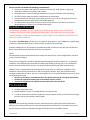
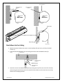
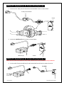
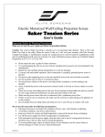
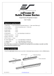
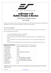
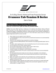
PowerMax / PowerMax Pro Series Electric/Motorized Front Projection Screen User’s Guide Important Safety & Warning Precautions Make sure to read this user’s guide and follow the procedures below. Caution: The screen’s Black Top Drop is already set to its maximum drop distance. There is NO extra Black Top Drop in the roller. Please be aware of this as it will void your warranty with Elite Screens. Unapproved changes or modifications (except for cutting the power cord for hardwire installations) to this unit are prohibited and will void your warranty. For more information, please contact our Technical Support Department at (877) 511-1211 Ext. 604. Please retain this user’s guide for future reference. To avoid damaging the unit, do not use with any unauthorized accessories not recommended by the manufacturer. Handle the unit carefully during transportation to avoid any damages. To ensure safe and reliable operation, direct connection to a properly grounded power source is advised. The power outlet supplying power to the unit should be close to the unit and easily accessible. Do not install the unit on uneven or inclined surfaces. Do not put heavy objects on the power cord and position it properly to avoid creating a trip obstacle. Never overload the power cord to prevent an electric shock or fire due to a loose contact or a short circuit. There are not user serviceable parts in this unit. Do not attempt to disassemble this unit by yourself. No one except authorized technicians can open and make repairs to this unit. Make sure the power source this unit is connected to has a continuous power flow. If there is need to use an extension cord, make sure the cord has an equal rating as the appliance to avoid overheat. Do not handle the power plug when your hands are wet or your feet are in contact with water. Rev.072512-JA 1 www.elitescreens.com/epv Do not use this unit under the following circumstances. Disconnect the power cord under the conditions of heavy rain, wind, thunder or lightning. Avoid direct Sunshine, rain shower and moisture. Keep away from fire sources and high temperature to prevent this device from overheating. Cut off the power supply first before transportation or maintenance. Fully disconnect from the power supply when the unit is not in use for a long period of time, as should be done with any other electric household appliance. To avoid possible injury and/or an electric shock, do not attempt to use the screen if there is obvious damage or if there are any evident broken parts. Installation Warning The instructions provided in this user’s guide are for reference only. Please consult a professional installation company for further installation and safety advice. The installer must insure that proper mounting hardware is used to provide adequate strength suitable for the installation. Elite Screens is not liable for any faulty installations. The Screen’s Top Black Drop is already set to its maximum drop distance. There is NO extra top black drop in the roller. Please be aware of this as it will void the limitation of your warranty. Individual modifications to this product are prohibited and will void the warranty with the manufacturer. Please contact Elite Screens Customer Service for any questions. NOTE: This equipment has been tested and found to comply with the limits for a Class B digital device, pursuant to Part 15 of the FCC Rules. These limits are designed to provide reasonable protection against harmful interference in a residential installation. This equipment generates and can radiate radio frequency energy and, if not installed and used in accordance with the instructions, may cause harmful interference to radio communications. However, there is no guarantee that the interference will not occur on a particular installation. If this equipment causes harmful interference to radio or television reception, which can be determined by turning the equipment off and on, the user is encouraged to try to correct the interference by one or more of the following measures. Reorient or relocate the receiving antenna of the device which may be causing the interference. Increase the separation between the screen and the device’s receiver. Connect the equipment into a different power outlet other than the device. Pre-Installation 1. Carefully unpack the screen. 2. Always handle the screen in a leveled position on a clean surface. 3. In order to protect the screen from exposure to stains, keep the screen out of contact with foreign particles such as dust, sawdust, and/or liquids. NOTE Regardless of the mounting method, the screen should be securely supported so that the vibration or pulling on the viewing surface will not cause the casing to become loose or fall. The installer must insure that the fasteners used are of adequate strength and suitable for the installation location. Rev.072512-JA 2 www.elitescreens.com/epv Hardware Parts List for the PowerMax Series Please make sure all parts listed below are included before proceeding with the installation. a. b. c. Hardware Parts List d. e. f. a. Mounting Bracket b. M4x50 Screw c. M10 Anchor d. Suspended Ceiling Bracket Connector e. M5x15 Screw& Bolt f. Bubble Leveler Installation Instructions Please consult a professional Installer. Elite Screens is not liable for faulty installations. Flush Mount to the Wall 1. Mark the location of where the screen is to be installed, drill your holes, and insert the M10 Anchors (c). 2. Install the Mounting Brackets (a) to the wall and secure with the M4x50 Screws (b). Anchor Fix Plate 1 M4x50 Screw Wall Mounting Bracket Fix Plate 2 Mounting Bracket 3. Attach the screen to the Mounting Bracket by inserting the top of the case to the first fix plate, and securing the back of the case to the second Fix Plate. Make sure the case slots are securely attached to the Mounting Bracket. Rev.072512-JA 3 www.elitescreens.com/epv QTY 2 4 4 2 4 1 Mounting Bracket Mounting Bracket Fix Plate 1 Mounting Bracket Fix Plate 2 Case Slot 1 Case Slot 2 Screen Case Flush Mount to the Ceiling 1. Mark the location of where the screen is to be installed, drill your holes, and insert the M10 Anchors (c). 2. Install the Mounting Brackets (a) to the ceiling and secure with the M4x50 Screws (b). Ceiling M10 Anchor Mounting Bracket Fix Plate 1 M4x50 Screw Mounting Bracket Fix Plate 2 3. Attach the screen to the Mounting Bracket by inserting the top of the case to the first Fix Plate, and securing the back of the case to the second Fix Plate. Make sure the case slots are securely attached to the Hanging Bracket. Rev.072512-JA 4 www.elitescreens.com/epv Fix Plate 1 Fix Plate 2 Suspended Ceiling using Chains(additional hardware required) 1. You can also hang the screen on a ceiling by using chains (not included). 2. Connect the Suspended Ceiling Bracket Connector (d) to the Mounting Bracket (a) and secure with the M5x15 Screws& Bolts (e). M5x15 Bolt (e) Suspended Ceiling Bracket Connector (d) Mounting Bracket (a) M5x15 Screw (e) 3. Insert chains (not included) through the loop holes of the Suspended Ceiling Bracket Connector (d). Suspended Ceiling Bracket Connector Loop Holes Built in 3 Way Control Switch 1. The PowerMax Series comes with a 3 Way Control Switch attached to the Power Cord, which is 3.5 meters in length. 2. Use the provided Bubble Level (f) to ensure the screen is leveled before plugging in the power cord. 3 Way Control Up/Stop/Down Switch Rev.072512-JA Bubble Leveler (f) 5 www.elitescreens.com/epv How to remove the screen from Mounting Brackets 1. Pull down on the Mounting Bracket Release Tab and remove the bottom of the case first, away from the wall/ceiling, followed by the top of the case. Release Tab Pull Bottom of case first away from wall/ceiling. ZPM-RT Optional Remote Control Kit for PowerMax Series (Standard for PowerMax Pro)1 Please contact Elite Screens to purchase the optional ZPM-RT Remote Control Kit. E F. In-wall RJ45 module 55” A. B. IR Remote RF Remote Red+ C. 3- way Wall Switch Green - D. 12V Trigger 110” E. IR ey receiver G. AAA batteries H. Wall box Rev.072512-JA 6 www.elitescreens.com/epv ZPM-RT Installation & Control Instructions1 1. Disconnect the 3 Way Control Switch from the PowerMax Screen as shown below. 3 Way Control Switch Screen 2. Connect the Wall Box (G) to the screen as shown below. Wall box (G) Screen ZPM-RT Installation & Control Instructions 2 Please consult a professonial installer for this procedure. Elite Screens is not responsible for faulty installations. 1. Cut the cable of both the Wall Box (G) and the attached Control Switch to expose the wires. Cut Cable Cut Cable Wall Box (G) Rev.072512-JA 7 www.elitescreens.com/epv 2. Connect the wires from the screen to the Wall box (G) according to their specific color. Purple Wire = Up Orange Wire = Down Yellow Wire = Common Yellow & Green Wire = Ground Purple Wire = Up Orange Wire = Down Yellow Wire = Common Yellow & Green Wire = Ground 3. The Wall Box (G) should be connected to your screen as shown below. Wall Box (G) 3 Way Wall Switch (C) 1. Connect the 3 Way Wall Switch (C) to the Wall Box (G) and mount on wall. Wall Box (G) 3 Way Wall Switch (C) Rev.072512-JA 8 www.elitescreens.com/epv 12 Volt Trigger (E) 1. Connect the 12 Volt Trigger (E) to the Wall Box (G)for set up to your projector. Wall Box (G) 12 Volt Trigger (E) Red Wire + DC12V Green Wire 0VConnect to Projector IR Eye Receiver (F) 1. Connect the IR Eye Receiver (F) to the Wall Box (G) for high wall or ceiling installations Wall Box (G) IR Remote (A) IR Eye Receiver (F) For a local Elite Screens contact or Technical Support, please visit www.elitescreens.com Rev.072512-JA 9 www.elitescreens.com/epv