1
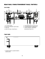
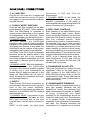
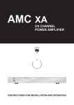
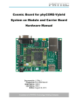
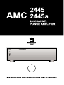
1. Since the 2445/2445a generates modest amounts of heat, adequate ventilation is
required. Do not place the amplifier on a soft surface such as a carpeted surface that may
block the ventilation holes of the bottom cover. Also, avoid obstructing the ventilation
holes in the top cover.
2. CAUTION: To prevent the risk of fire or shock, do not allow any liquid or moisture to
enter into the internal parts of this product. If any liquid accidentally enters this product,
shut off the power and remove the AC power cord immediately. If the liquid is anything
other then clean water or pure alcohol, have the product examined by a service
technician. Servicing of this product should be referred to a qualified service technician.
120V 60Hz
SPEAKER
CH 1
SPEAKER
+
+
CH 2
TRIGGER
AUDIO SENSE
+
OUT
IN
12V
DC
3-30V
AC/DC
SPEAKER
4CH
CH 3
SPEAKER
+
+
SWITCHED
CH 4
CONSTANT
RIGHT
2/4 Channel Power Amplifier 2445a
+
TOTAL 2A MAX 240W
LEFT
INPUT LEVEL
INPUT LEVEL
ADJ.
ADJ.
120V
60Hz
3A
UNSWITCHED 2A MAX 240W
INPUT
INPUT
2 CH
2 CH
4 CH
RIGHT CH
1. AC LINE CORD
2. 2CH/4CH "MODE" SWITCHES
3. INPUTS
4. INPUT LEVEL CONTROLS
2/4 Channel Power Amplifier 2445a
H.O.M.E. AUTOMATION SERIES
POWER
1
1. POWER SWITCH AND POWER
INDICATOR
2CH
4 CH
LEFT CH
5. CONVENIENCE AC OUTLETS
6. LOUDSPEAKER TERMINALS
7. AUDIO SENSE/ TRIGGER/
CONSTANT SWITCH
1. AC LINE CORD.
Plag the AC line cord into a nearby wall
outlet that provides the correct AC power
line voltage, or into a convenience outlet on
any AMC product.
2. 2CH/4CH "MODE" SWITCHES.
There are two slide switches on the back
panel labelled "2CH 4CH". These switches
allow the 2445/2445a to opreated in
several modes depending on the number
of loudspeakers to be connected. These
modes of operation are defined as follows;2 CHANNEL MODE. With both switches in
the 2CH. position, the 2445/2445a
becomes a two channel (stereo) amplifier
capable of driving two 8 ohm loudspeakers
at 90 watts per channel. In this mode, the
2445/2445a can be used as a high power,
audiophile quality, stereo power amplifier.
CAUTION: In the 2CH. mode, the speaker
terminals should be directly wired to the
loudspeaker and not to any accessory
device like headphones adaptors etc. That
may share a common ground with other
channels.
4 CHANNEL MODE. With both switches in
the 4CH. position, the 2445/2445a
becomes a four channel amplifier capable
of driving four 4 ohm loudspeakers at
greater than 45 watts per channel. In this
mode, the 2445/2445a can be used for
Dolby surround sound systems and multiroom type applications.
3. INPUTS.
There are four RCA photo connectors on
the back panel that connect to the inputs of
each of the four power amplifiers.
Connections to these inputs are made with
reference to the MODE SWITCH settings
described above;2 CHANNEL MODE. Connections for the
left channel input can be made via CH3
RCA input connector and for the right
channel input, use the input connector of
CH1.
NOTE: In this mode, the input photo
connectors of CH2 and CH4 are
disconnected.
4 CHANNEL MODE. In this mode, the
2445/2445a opreates as a 4 channel
amplifier. Connections to the inputs of
these amplifiers are made through the RCA
phono connectors of CH1 through 4.
4. INPUT LEVEL CONTROLS.
Each channel of the 2445/2445a has its
own, independant level control. Before
turning on the 2445/2445a for the first time,
make sure that all level controls are set to
their fully clockwise position. These
controls can be used for various functions.
For example, they can be used to match
the levels of loudspeakers in a multi-room
installation, or to lower the sensitivity of the
power amplifier, so that the volume control
on the pre-amplifier is at a more convenient
and usable position. They can also be used
to optimise the balance in a stereo system.
NOTE: In the 2 channel mode, only the
input levelcontrols of CH1 and CH3 are
operative. The controls for CH2 and CH4
are switched out of circuit.
5. CONVENIENCE AC OUTLETS.
There are 2 switched AC outlets and one
unswitched outlet on the back panel of
120V versions of the 2445/2445a. For
220V/230V/240V version. there is only one
unswitched AC outlet. These outlets can be
used to provide AC power for other audio or
video components.
6. LOUDSPEAKERS TERMINALS
The 2445/2445a is equipped with binding
post type speaker terminals that are
designed to handle the extremely high
peak currents that this amplifier is capable
of giving. Connections from these
terminals to the loudspeakers should be
made with heavy-duty wire. Stranded wire
of 16 gaugeor thicker is recommended
especially if low impedance loudspeakers
are used. The following describes the
connections for 2 channel and 4 channel
operation;4 CHANNEL MODE. When the MODE
SWITCH of the 2445/2445a are set to 4
channel operation, simply connect the
wires from one loudspeaker to the
terminals (marked - and +) of CH1, the
second speaker to CH2 and so on. Make
sure that the red terminal on each
loudspeaker is connected to the
corresponding red terminal on the amplifier
and likewise for the blck terminals.
2 CHANNEL MODE. When the MODE
SWITCHES are set to 2 channel opreation,
only the red terminals on the 2445/2445a
areused. For this mode of opreation,
connect the red terminal of the right
speaker to the red terminal of CH1 and the
black speaker terminal to the red terminal
of CH2. The left speaker is connected in a
similar way, where the red terminal of the
speaker is connectored to the red terminal
of CH3 and the black terminal of the
speaker is connected to the red terminal of
CH4.
NOTE: The 2445 amplifier is normally used
in 2 or 4 channel modes. However, it can
also be set to operate as a 3 channel
amplifier that is capable of driving one 8
ohm loudspeaker at 90 watts and two 4
ohm loudspeakers at greater than 45 watts
per channel. Typical applications include,
satellite/subwoofer systems and Dolby
surround sound decoder systems. To set
the 2445/2445a in this mode of operation,
please consult your AMC dealer.
7. AUDIO SENSE/TRIGGER/CONSTANT
SWITCH
The remote power switch is located on the
back panel of the AMC 2445a and provides
the following functions; (note that this
feature is only valid for 2445a, please skip
to next part if your model is 2445)
AUDIO SENSE. When the remote power
switch is set in the AUDIO SENSE
position, the 2445a is turned on or off
automatically, depending on the audio
signal level at the inputs. With an audio
signal greater than 10 mV at any of the
four stereo inputs of 2445a, the amplifier
will automatically turn on. If the signal
level drops below this level, the amplifier
will remain on for a period of
approximately 5 minutes before it
automatically reverts to stand_by mode.
Please note that when AC power is first
applied to the 2445a while the remote
power switch is in the AUDIO SENSE
position, the amplifier will automatically
turn on, even without an audio signal
being present at any of the audio inputs.
However, after approximately 5 minutes,
the amplifier will revert to stand_by mode,
assuming no signals are present at any of
the inputs.
TRIGGER. When the remote power
switch is set in the TRIGGER position,
the AMC 2445a can be turned on
automatically by an external trigger
voltage. The trigger voltage is applied to
the trigger input socket, located on the
back panel of the 2445a. This trigger
voltage can originate from a system
controller or from another 2445a. The
sensitivity of this input ranges from +3Vdc
to +30Vdc and will also accept AC
voltages over the same range. The
current required from the trigger source is
only 0.2mA.
The 2445a is also provided with a trigger
output socket, also located on the back
panel. When the 2445a is turned on, the
trigger output socket provides a +12Vdc
signal that can be looped through or
"daisy_chained" to the trigger input of
another 2445a amplifier (or other
component) in a multi component
installation. When the external trigger
voltage is set to 0V, the 2445a will be in
stand_by mode and the voltage from the
trigger output socket will likewise be 0V.
CONSTANT. When the remote power
switch is set in the CONSTANT position,
the power on and off states of the AMC
2445a are controled by the front panel
master power on/off switch. In this position,
the 2445a has the same functionality as the
original 2445.
NOTE: The bi-color power LED above the
front panel power switch, indicates the
power status of the 2445a. This LED will
light up RED when the 2445a is in standby mode and GREEN when turned on.
FRONT PANEL.
1.POWER SWITCH AND POWER.
The press button switch marked power can
be used to switched the 2445/2445a on or
off. When the 2445/2445a is switched on,
the led above the power switch will light.
2 CHANNEL MODE
Power output into 8 ohms (20Hz~20KHz) ..............................................................90W
With both channels driven
Rated THD. .......................................................................................................0.03%
1KHz clipping power into 8 ohm ........................................................................100W
Damping factor ....................................................................................................>100
Input sensitivity for 1W/90W into 8 ohm ................................................91mV/866mV
4 CHANNEL MODE
Power output into 4 ohms (20Hz-20KHz) .......................................................... ..45W
With all channels driven
Rated THD. .......................................................................................................0.05%
1KHz clipping power into 4 ohm ..........................................................................50W
Damping factor ....................................................................................................>100
Input sensitivity for 1W/45W into 4 ohms ............................................130mV/866mV
Input impedance ................................................................................R=10K C=200pf
Frequency response 20Hz~20KHz ................................................................+/-0.5dB
"A" WTD. singal to noise ratio (ref. 1W/8 ohms) ...............................................100dB
Dimensions (WxHxD) .......................................................................430x112x288mm
Net weight ...........................................................................................................9.5kg
Shipping weight ................................................................................................10.5kg
Power consumption ............................................................................................360W
Weltronics Corp. reserved the right to improve its products at any time. Specifications are
subject to change without notice.
1. READ INSTRUCTIONS
16. DAMAGE REQUIRING SERVICE
All the safety and operating instructions should be read
before the appliance is operated.
2. RETAIN INSTRUCTIONS
The safety and operating instructions should be retained for
future reference.
3. HEED WARNINGS
All warnings on the appliance and in the operating instructions
should be adhered to.
4. FOLLOW INSTRUCTIONS
All operating and use instructions should be followed.
5. WATER AND MOISTURE
The appliance should not be used near water - for example,
near a bathtub, washbowl, kitchen sink, laundry tub, in a wet
basement, or near a swimming pool, etc.
6. CARTS AND STANDS
The appliance should be used only with a cart or stand that is
recommended by the manufacturer.
6A. An appliance and cart combination should be
moved with care. Quick stops, excessive force,
and uneven surfaces may cause the appliance
and cart combination to overturn.
7. WALL OR CEILING MOUNTING
PORTABLE CART WARNING
S3125A
This equipment is not designed for use mounted on a wall or a
ceiling.
8. VENTILATION
The appliance should be situated so that its location or position
does not interfere with its proper ventilation. For example, the
appliance should not be situated on a bed, sofa, rug, or similar
surface that may block the ventilation openings, or placed in a
built-in installation, such as bookcase or cabinet that may
impede the flow of air through the ventilation openings.
9. HEAT
The appliance should be situated away from heat sources
such as radiators, heat registers, stoves, or other appliances
(including amplifiers) that produce heat.
The appliance should be serviced by qualified service
personnel when:
a) The power-supply cord or the plug has been damaged; or
b) Objects have fallen, or liquid has been spilled into the
appliance; or
c) The appliance has been exposed to rain; or
d) The appliance does not appear to operate normally or
exhibits a marked change in performance; or
e) The appliance has been dropped, or the enclosure is
damaged.
17. POWER LINES
(APPLIES TO TUNER AND RECEIVERS ONLY)
An outdoor antenna should be located away from power lines.
18. OUTDOOR ANTENNA GROUNDING
(APPLIES TO TUNER AND RECEIVERS ONLY)
If an outside antenna is connected to the receiver, be sure the
antenna system is grounded so as to provide some protection
against voltage surges and built up static charges.
Section 810 of the National Electrical Code, ANSI/NFPA No.
70-1984, provides information with respect to proper
grounding of the mast and supporting structure, grounding of
the lead-in wire to an antenna discharge unit, size of grounding
conductors, location of antenna-discharge unit, connection to
grounding electrodes, and requirements for the grounding
electrode. See Figure.
a) Use No. 10 AWG (5.3 mm2) copper, No. 8 AWG (8.4 mm2)
aluminum, No. 17 AWG (1.0 mm2) copper-clad steel or
bronze wire, or larger, as a ground wire.
b) Secure antenna lead-in and ground wires to house with
stand-off insulators spaced from 4-6 feet (1.22-1.83 m)
apart.
c) Mount antenna discharge unit as close as possible to where
lead-in enters house.
d) Use jumper wire not smaller than No.6 AWG (13.3 mm2)
copper, or the equivalent, when a separate antennagrounding electrode is used. See NEC Section 810-21(j).
Antenna Grounding According to
the National Electrical Code
10. POWER SOURCES
The appliance should be connected to a power supply only of
the type described in the operating instructions or as marked
on the appliance.
Antenna Lead
In Wire
11. POWER-CORD PROTECTION
Power-supply cords should be routed so that they are not likely
to be walked on or pinched by items placed upon or against
them, paying particular attention to cords at plugs,
convenience receptacles, and the point where they exit from
the appliance
12. CLEANING
The appliance should be cleaned only as recommended by
the manufacturer.
Ground
Clamp
Electric
Service
Equipment
The power cord of the appliance should be unplugged from the
outlet when left unused for a long period of time.
Power Service Grounding
Electrode System
(NEC Art 250 Part H)
14. OBJECT AND LIQUID ENTRY
15. SERVICING
The user should not attempt to service the appliance beyond
that described in the operating instructions. All other servicing
should be referred to qualified service personnel.
Grounding Conductors
(NEC Section 810.21)
Ground Clamps
13. NON USE PERIODS
Care should be taken so that objects do not fall and liquids are
not spilled into the enclosure through openings.
Antenna
Discharge
Unit (NEC
Section 810.20)
National Electrical Code
Available from Library, book
stores, or National Fire Protection
Association (Batterymarch Park,
Quincy. MA 02269).
AMC 21-3004