1
30
7.0 Site Requirements
50
28
7.9
&8
26
NOTE: Please read this section in conjunction with
the instructions supplied in the kit. The table opposite
supplements information in the kit literature.
0
24
22
0/2
10
20
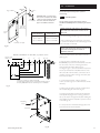
70Ø Exhaust (metres) X
18
Plume Displacement Kit
1. This kit is recommended for installations where the
condensate plume emitted from the flue may cause a
nuisance or affect the surroundings.
2. The flue consists of two main parts. The concentric
part, most of which is fitted inside and the 70Ø part
which is entirely outside the building.
16
14
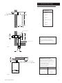
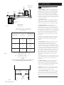
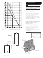
3. Full fitting details are supplied with the kit. The table
and illustration opposite show the maximum permissible
lengths of each part of the flue (Fig 17a).
12
10
4. The required length of one part of the flue affects the
maximum permissible length of the other. For example,
when fitting a 100/2 HE the table shows that if 14 metres
of 70Ø are required outside, up to 2 metres of
concentric flue can be used.
8
6
4
5. This is determined by finding the 14 metre mark on
the left hand part of the graph, and tracing across to the
sloping line marked ‘100/2 HE’. Then trace vertically
down to the bottom part of the graph - this gives a
concentric maximum of 2 metres.
2
0
0
1
2
3
4
Concentric 70/110 Flue (metres) Y
Fig. 17a
6. Further worked examples are shown in the literature
supplied with the kit.
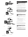
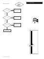
IMPORTANT: If fitting a Plume
Displacement Flue Kit, the air inlet
must be a minimum of 100mm from
any opening windows or doors (see
Section 7.9).
70Ø Exhaust
X
Plume
Displacement Kit
Y
Air Inlet
Concentric 70/110 Flue
(MUST be installed
horizontally)
Fig. 17b
© Baxi Heating UK Ltd 2006
Opening Window
or Door
100mm
MIN.
Fig. 17c
21