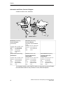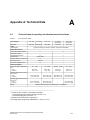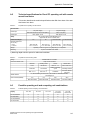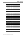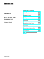
1
Preface, Table of Contents
SIMATIC PC
Panel PC 670 / 870
Operating Unit
Product Overview
1
Description of Device
2
Mounting
3
Maintenance
4
Remote Mount Form Factor
5
Equipment Manual
Appendices
Technical Data, Keyboard Table
A
ESD Guidelines
B
Index
Edition 07/02
Safety information
This manual contains information which you must observe for your personal safety and to
prevent material damage. The information is denoted by a warning triangle and is differentiated as follows, depending on the degree of danger:
!
!
!
Danger
indicates an imminently hazardous situation which, if not avoided, will result in death or
serious injury.
Warning
indicates a potentially hazardous situation which, if not avoided, could result in death
or serious injury.
Caution
used with the safety alert symbol indicates a potentially hazardous situation which, if
not avoided, may result in minor or moderate injury.
Caution
used without the safety alert symbol indicates a potentially hazardous situation which, if
not avoided, may result in property damage.
Notice
indicates a situation which, if not avoided, could give rise to an undesirable result or
state.
Note
is an important piece of information about the product, the handling of the product or a
particular part of the documentation to which attention is to be drawn.
Qualified personnel
Only qualified personnel are permitted to start up and operate the device. Qualified
personnel for the purposes of the safety information in this manual are persons who
hold the necessary authorization to install, ground and label devices, systems and circuits in accordance with the standards of safety engineering.
Correct usage
Please note the following:
!
Warning
The device may only be used for the application cases specified in the catalog and the
technical description and may only be used in combination with third-party equipment
and components recommended or approved by Siemens.
Startup must not take place until it is established that the machine which is to
accommodate this component is in conformity with the guideline 98/37 EC.
Appropriate transport, and appropriate storage, installation and assembly, as well as
careful operation and maintenance, are required to ensure that the product operates
perfectly and safely.
Trademarks
You will find the registered trademarks of Siemens AG in the preface.
The remaining marks used in this publication (or on the CD) may be
trademarks, the use of which by third parties for their own purposes
could violate the rights of the owner.
Impressum
Editor and Publisher: A&D PT1
Copyright Siemens AG 2002 All rights reserved
Exclusion of liability
The transmission and reproduction of this documentation and the exploitation
and communication of its contents are not permitted without express
authority. Offenders will be liable for compensation for damage. All rights
reserved, especially in the case of the granting of a patent or registration of a
utility model or design
We have checked the content of this publication for compliance with the
described hardware and software. However, discrepancies cannot be
excluded, with the result that we cannot guarantee total compliance. The
information in this publication is, however, checked regularly, and any
necessary corrections are included in the following editions. We welcome any
suggestions for improvement.
Siemens AG
Automation & Drives
SIMATIC Human Machine Interface
Postfach 4848, D-90327 Nürnberg
E Siemens AG 2002
Subject to technical changes.
Siemens Aktiengesellschaft
Edition 07/02
Preface
Purpose of the manual
This manual contains information which you require when using the operating unit of
the SIMATIC Panel PC 670 or PC 870. With this information you can:
S
become acquainted with the functions and components of the operating unit,
S
separate the operating unit from the computing unit,
S
install the Panel PC
1. Centrally (installed with operating unit and computing unit integrated), or
2. in remote mount form factor (operating unit and computing unit installed separately, refer to Chapter 5)
S
perform upgrades and install spare parts, providing you fulfill the necessary conditions.
Target group
The manual is supplied as an electronic document in PDF-format together with the SIMATIC Panel PC 670 or PC 870 and has been written for the following readers:
S
users who commission the device themselves or work with the Panel PC
(editing, testing),
S
service and maintenance engineers who perform conversions and install
upgrades or spare parts.
SIMATIC Panel PC 670 / 870 Operating Unit, Equipment Manual
Edition 07/02
v
Preface
Documentation
S
Commissioning Instructions
The Commissioning Instructions are supplied as a paper document. The document
is intended for commissioning engineers and system administrators.
The Commissioning Instructions describe briefly the most important steps for commissioning the hardware and software.
S
SIMATIC Panel PC 670/PC 870 Operating Unit Equipment Manual
The manual is supplied on CD together with the SIMATIC Panel PC 670 or
PC 870 as an electronic document in PDF-format. It is intended for the
commissioning engineers and service and maintenance technicians who install the
Panel PC and perform maintenance work on the operating unit.
Furthermore, the Equipment Manual provides an overview of how to use the controls of the operating unit.
S
SIMATIC Panel PC 670 Computing Unit Equipment Manual
The manual is supplied on CD together with the SIMATIC Panel PC 670 as an
electronic document in PDF-format. It is intended for the commissioning engineers,
and service and maintenance technicians who install upgrades or perform error
analyses on the computing unit.
S
SIMATIC Panel PC 870 Computing Unit Equipment Manual
The manual is supplied on CD together with the SIMATIC Panel PC 870 as an
electronic document in PDF-format. It is intended for the commissioning engineers,
and service and maintenance technicians who install upgrades or perform error
analyses on the computing unit.
Notation
The following conventions are used in this manual:
vi
Motor off
Text that is displayed on the operating unit is printed in
Courier typeface.
Variable
Symbolic names that stand for variable values appearing on
the screen are printed in Courier italic typeface.
Screens
Selectable functions are printed in standard italic typeface.
ESC
Names of keys and buttons are shown in a different typeface.
SIMATIC Panel PC 670 / 870 Operating Unit, Equipment Manual
Edition 07/02
Preface
History
Edition
Comments
03/00
Initial release of the equipment manual SIMATIC Panel PC 670 –
Operating Unit.
07/01
Initial release of the equipment manual SIMATIC Panel PC 670/870 –
Operating Unit.
12/01
Extension to include the ”remote mount form factor” option of the SIMATIC Panel PC 670/870 – operating Unit equipment manual.
07/02
Technical update of the SIMATIC Panel PC 670/870 – Operating unit
equipment manual.
Trademarks
The following names are registered trademarks of Siemens AG:
S
SIMATICR
S
SIMATIC HMIR
S
HMIR
S
ProToolR
S
ProTool/LiteR
S
ProTool/ProR
S
SIMATIC Multi PanelR
S
SIMATIC Multifunctional PlatformR
S
MP 270R
S
ProAgentR
SIMATIC Panel PC 670 / 870 Operating Unit, Equipment Manual
Edition 07/02
vii
Preface
Automation and Drives, Service & Support
Available round the clock, worldwide:
Nuremberg
Johnson City
Singapore
SIMATIC Hotline
Worldwide (Nuremberg)
Worldwide (Nuremberg)
Technical Support
Technical Support
(FreeContact)
(fee-based, only with SIMATIC
Card)
Local time: Mon.-Fri. 8:00 to 17:00
Local time: Mon.-Fri. 0:00 to 24:00
Telephone: +49 (180) 5050-222
Telephone: +49 (911) 895-7777
Fax:
+49 (180) 5050-223
Fax:
+49 (911) 895-7001
E-Mail:
techsupport@
ad.siemens.de
+1:00
GMT:
+01:00
GMT:
Europe / Africa (Nuremberg)
America (Johnson City)
Asia / Australia (Singapore)
Authorization
Technical Support and
Authorization
Technical Support and
Authorization
Local time: Mon.-Fri. 8:00 to 17:00
Local time: Mon.-Fri. 8:00 to 19:00
Local time: Mon.-Fri. 8:30 to 17:30
Telephone: +49 (911) 895-7200
Telephone: +1 423 461-2522
Telephone: +65 740-7000
Fax:
+49 (911) 895-7201
Fax:
+1 423 461-2289
Fax:
+65 740-7001
E-Mail:
authorization@
nbgm.siemens.de
+1:00
E-Mail:
simatic.hotline@
sea.siemens.com
–5:00
E-Mail:
simatic.hotline@
sae.siemens.com.sg
+8:00
GMT:
GMT:
GMT:
The languages spoken by the SIMATIC Hotlines are generally German and English,
the Authorization Hotline is also provided in French, Italian and Spanish.
viii
SIMATIC Panel PC 670 / 870 Operating Unit, Equipment Manual
Edition 07/02
Preface
SIMATIC Customer Support Online Services
The SIMATIC Customer Support team offers you substantial additional information
about SIMATIC products via its online services:
S
General current information can be obtained
– in the Internet unter
http://www.siemens.com/simatic
S
Current Product Information leaflets, FAQs (Frequently Asked Questions),
Downloads, Tips and Tricks can be obtained
– in the Internet under
http://www.siemens.com/automation/service&support
Training Center
Siemens offers a number of training courses to familiarize you with the SIMATIC S7
automation system. Please contact your regional training center or our central training
center in D 90327 Nuremberg, Germany for details.
Telephone:
+49 (911) 895–3200
Internet:
http://www.sitrain.com
E-Mail:
[email protected]
Other Sources of Assistance
In case of technical queries, please contact the Siemens representatives in the
subsidiaries and branches responsible for your area.
The addresses can be found:
S
in the Siemens Catalogue ST 80
S
in the Internet under
http://www.siemens.com/automation/partner
S
in the Interactive Catalogue CA01
http://www.siemens.com/automation/ca01
SIMATIC Panel PC 670 / 870 Operating Unit, Equipment Manual
Edition 07/02
ix
Preface
x
SIMATIC Panel PC 670 / 870 Operating Unit, Equipment Manual
Edition 07/02
Table of Contents
Table of Contents
1
2
3
4
Preface . . . . . . . . . . . . . . . . . . . . . . . . . . . . . . . . . . . . . . . . . . . . . . . . . . . . . . . . . . . . . . . .
i
Product Overview . . . . . . . . . . . . . . . . . . . . . . . . . . . . . . . . . . . . . . . . . . . . . . . . . . . . . .
1-1
1.1
Panel PC 670: Computing and operating units . . . . . . . . . . . . . . . . . . . . . . .
1-2
1.2
Panel PC 870: Computing and operating units . . . . . . . . . . . . . . . . . . . . . . .
1-4
Description of Device . . . . . . . . . . . . . . . . . . . . . . . . . . . . . . . . . . . . . . . . . . . . . . . . . . .
2-1
2.1
2.1.1
2.1.2
2.1.3
Operating units with key-based front panels . . . . . . . . . . . . . . . . . . . . . . . . .
Status indicators . . . . . . . . . . . . . . . . . . . . . . . . . . . . . . . . . . . . . . . . . . . . . . . .
Keyboard . . . . . . . . . . . . . . . . . . . . . . . . . . . . . . . . . . . . . . . . . . . . . . . . . . . . . .
Integrated mouse . . . . . . . . . . . . . . . . . . . . . . . . . . . . . . . . . . . . . . . . . . . . . . .
2-2
2-2
2-3
2-5
2.2
Operating units with touchscreen front panels . . . . . . . . . . . . . . . . . . . . . . .
2-6
2.3
2.3.1
2.3.2
2.3.3
Interfaces . . . . . . . . . . . . . . . . . . . . . . . . . . . . . . . . . . . . . . . . . . . . . . . . . . . . . .
Front-side USB interface . . . . . . . . . . . . . . . . . . . . . . . . . . . . . . . . . . . . . . . . .
Rear-side interfaces . . . . . . . . . . . . . . . . . . . . . . . . . . . . . . . . . . . . . . . . . . . . .
Interface assignment . . . . . . . . . . . . . . . . . . . . . . . . . . . . . . . . . . . . . . . . . . . .
2-7
2-7
2-7
2-8
2.4
2.4.1
2.4.2
Device dimensions . . . . . . . . . . . . . . . . . . . . . . . . . . . . . . . . . . . . . . . . . . . . . .
Dimensions of Panel PC 670 in standard mount form factor . . . . . . . . . . .
Dimensions of Panel PC 870 in standard mount form factor . . . . . . . . . . .
2-9
2-9
2-10
Mounting . . . . . . . . . . . . . . . . . . . . . . . . . . . . . . . . . . . . . . . . . . . . . . . . . . . . . . . . . . . . . .
3-1
3.1
3.1.1
3.1.2
Mounting cut-out . . . . . . . . . . . . . . . . . . . . . . . . . . . . . . . . . . . . . . . . . . . . . . . .
Panel PC 670 . . . . . . . . . . . . . . . . . . . . . . . . . . . . . . . . . . . . . . . . . . . . . . . . . . .
Panel PC 870 . . . . . . . . . . . . . . . . . . . . . . . . . . . . . . . . . . . . . . . . . . . . . . . . . . .
3-2
3-2
3-3
3.2
3.2.1
3.2.2
Installation . . . . . . . . . . . . . . . . . . . . . . . . . . . . . . . . . . . . . . . . . . . . . . . . . . . . .
Panel PC 670 . . . . . . . . . . . . . . . . . . . . . . . . . . . . . . . . . . . . . . . . . . . . . . . . . . .
Panel PC 870 . . . . . . . . . . . . . . . . . . . . . . . . . . . . . . . . . . . . . . . . . . . . . . . . . . .
3-4
3-4
3-6
Maintenance . . . . . . . . . . . . . . . . . . . . . . . . . . . . . . . . . . . . . . . . . . . . . . . . . . . . . . . . . . .
4-1
4.1
4.1.1
4.1.2
Spare parts and accessories . . . . . . . . . . . . . . . . . . . . . . . . . . . . . . . . . . . . . .
Spare parts . . . . . . . . . . . . . . . . . . . . . . . . . . . . . . . . . . . . . . . . . . . . . . . . . . . . .
Accessories . . . . . . . . . . . . . . . . . . . . . . . . . . . . . . . . . . . . . . . . . . . . . . . . . . . .
4-1
4-1
4-1
4.2
Detaching the operating unit in standard mount form factor from the
computing unit . . . . . . . . . . . . . . . . . . . . . . . . . . . . . . . . . . . . . . . . . . . . . . . . . .
Panel PC 670 . . . . . . . . . . . . . . . . . . . . . . . . . . . . . . . . . . . . . . . . . . . . . . . . . . .
Panel PC 870 . . . . . . . . . . . . . . . . . . . . . . . . . . . . . . . . . . . . . . . . . . . . . . . . . . .
4-2
4-2
4-4
4.2.1
4.2.2
SIMATIC Panel PC 670 / 870 Operating Unit, Equipment Manual
Edition 07/02
xi
Table of Contents
4.3
5
A
B
Replacing soft key labeling
(operating units with key-based front panels only) . . . . . . . . . . . . . . . . . . . .
4-6
Remote Mount Form Factor . . . . . . . . . . . . . . . . . . . . . . . . . . . . . . . . . . . . . . . . . . . . .
5-1
5.1
5.1.1
5.1.2
Overview . . . . . . . . . . . . . . . . . . . . . . . . . . . . . . . . . . . . . . . . . . . . . . . . . . . . . . .
Configuration . . . . . . . . . . . . . . . . . . . . . . . . . . . . . . . . . . . . . . . . . . . . . . . . . . .
Block diagram . . . . . . . . . . . . . . . . . . . . . . . . . . . . . . . . . . . . . . . . . . . . . . . . . .
5-2
5-2
5-4
5.2
5.2.1
5.2.2
5.2.3
Description . . . . . . . . . . . . . . . . . . . . . . . . . . . . . . . . . . . . . . . . . . . . . . . . . . . . .
Overview . . . . . . . . . . . . . . . . . . . . . . . . . . . . . . . . . . . . . . . . . . . . . . . . . . . . . . .
Dimensions . . . . . . . . . . . . . . . . . . . . . . . . . . . . . . . . . . . . . . . . . . . . . . . . . . . . .
Mounting . . . . . . . . . . . . . . . . . . . . . . . . . . . . . . . . . . . . . . . . . . . . . . . . . . . . . . .
5-5
5-5
5-6
5-7
5.3
Cable connection . . . . . . . . . . . . . . . . . . . . . . . . . . . . . . . . . . . . . . . . . . . . . . . .
5-8
5.4
Spare parts . . . . . . . . . . . . . . . . . . . . . . . . . . . . . . . . . . . . . . . . . . . . . . . . . . . . .
5-8
5.5
Technical specifications . . . . . . . . . . . . . . . . . . . . . . . . . . . . . . . . . . . . . . . . . .
5-8
Appendix A: Technical Data . . . . . . . . . . . . . . . . . . . . . . . . . . . . . . . . . . . . . . . . . . . . .
A-1
A.1
Technical data of operating unit standard mount form factor . . . . . . . . . . .
A-1
A.2
Technical specifications for Panel PC operating unit with remote mount
form factor . . . . . . . . . . . . . . . . . . . . . . . . . . . . . . . . . . . . . . . . . . . . . . . . . . . . .
A-3
A.3
Possible operating unit and computing unit combinations . . . . . . . . . . . . .
A-3
A.4
Keyboard table (operating units with key-based front panels) . . . . . . . . . .
A-4
Appendix B: ESD Guidelines . . . . . . . . . . . . . . . . . . . . . . . . . . . . . . . . . . . . . . . . . . . .
B-1
Index . . . . . . . . . . . . . . . . . . . . . . . . . . . . . . . . . . . . . . . . . . . . . . . . . . . . . . . . . . . . . . . . . . Index-1
xii
SIMATIC Panel PC 670 / 870 Operating Unit, Equipment Manual
Edition 07/02
Product Overview
Usage
1
The SIMATIC Panel PC 670/870 is an industry-standard PC platform for
demanding tasks in the field of PC-based automation. The Panel PC is designed for on-site use on the machine, installed for example in
S
19” cabinets/racks,
S
Control cabinets and consoles,
S
Swivel arms (booms).
The SIMATIC Panel PC 670/870 is available in two configurations:
S
Panel PC in standard mount form factor (computing unit and operating
unit integrated)
S
or as a Panel PC in remote mount form factor (computing unit and operating unit spatially separated, refer to Chapter 5).
The present equipment manual describes
S
Chapters 2 to 4 basically describe the specific characteristics of the
operating unit, but also make reference to the complete unit where necessary – for example, with regard to the dimensions for mounting,
maintenance and technical specifications.
S
Chapter 5 describes the remote mount form factor of the Panel PC.
SIMATIC Panel PC 670 / 870 Operating Unit, Equipment Manual
Edition 07/02
1-1
Product Overview
1.1
Panel PC 670: Computing and operating units
The computing unit is screwed to the rear of the operating unit with two
mounting rails and can be separated from the latter. Figure 1-1 shows an example of
the complete device and indicates the connection between the computing unit and the
operating unit (2 of the 4 screw joints are marked with circles). Details on how to separate the two components are contained in Section 4.2.1.
Computing unit
Fig. 1-1
Brief description
Operating unit
Panel PC: Computing unit and operating unit
The SIMATIC Panel PC 670 can be supplied with various operating units,
which differ by way of their display size and style of operation, which is either by membrane keyboard or touchscreen.
The following different versions are available:
Keyboard versions
S
1-2
Color display with back-lighting
– 10.4” TFT screen; 640 x 480 pixel resolution
or
– 12.1” TFT screen; 800 x 600 pixel resolution
or
– 15.1” TFT screen; 1024 x 768 pixel resolution
SIMATIC Panel PC 670 / 870 Operating Unit, Equipment Manual
Edition 07/02
Product Overview
S
Membrane keyboard with alpha, numeric, cursor and control keypad
S
Function keys/soft keys
– 2 x 8 vertical rows of keys with soft-key and optional direct–key
functions
– 2 x 10 horizontal rows of keys with soft-key functions
– labeling strips for the rows of soft keys
S
Shift key for switching to the second level of key functions
S
Integrated piezo mouse
S
Status LEDs for power supply and temperature
S
USB interface on front side
for connecting external peripheral devices
S
Degree of protection up to IP 65 1) depending on version
S
Mounting: Clamps on rear side or 19” screw fixing
Touchscreen versions
S
Color display with back-lighting
– 12.1” TFT screen; 800 x 600 pixel resolution
or
– 15.1” TFT screen; 1024 x 768 pixel resolution
S
Status LEDs for power supply and temperature
S
USB interface on front side
for connecting external peripheral devices 2)
S
Degree of protection up to IP 65 / NEMA 4 1)
depending on version
S
Mounting: Clamps on rear side;
alternatively 19” screw fixing for 15.1” version
_______________________________________________________
1)
2)
see Technical Data (Appendix)
not for option “operating unit without front side USB interface” (see Technical Data in Appendix)
SIMATIC Panel PC 670 / 870 Operating Unit, Equipment Manual
Edition 07/02
1-3
Product Overview
1.2
Panel PC 870: Computing and operating units
The computing unit is screwed to the rear of the operating unit with two mounting rails
and can be separated from the latter (see Section 4.2.2).
Figure 1-2 shows an example of the complete device:
Operating unit
Fig. 1-2
Brief description
Computing unit
Panel PC 870: Complete device, comprising computing unit and
operating unit
The SIMATIC Panel PC 870 can be supplied with various operating units,
which differ by way of their display size and style of operation, which is either by membrane keyboard or touchscreen.
The following different versions are available:
Keyboard versions
1-4
S
Color display with back-lighting
– 12.1” TFT screen; 800 x 600 pixel resolution
or
– 15.1” TFT screen; 1024 x 768 pixel resolution
S
Membrane keyboard with alpha, numeric, cursor and control keypad
SIMATIC Panel PC 670 / 870 Operating Unit, Equipment Manual
Edition 07/02
Product Overview
S
Function keys/soft keys
– 2 x 8 vertical rows of keys with soft-key and optional direct-key
functions
– 2 x 10 horizontal rows of keys with soft-key functions
– labeling strips for the rows of soft keys
S
Shift key for switching to the second level of key functions
S
Integrated piezo mouse
S
Status LEDs for power supply and temperature
S
USB interface on front side
for connecting external peripheral devices
S
Degree of protection up to IP 65 1) depending on version
S
Mounting: Clamps on rear side or 19” screw fixing
Touchscreen version
S
Color display with back-lighting,
– 12.1” TFT screen; 800 x 600 pixel resolution 3)
or
– 15.1” TFT screen; 1024 x 768 pixel resolution
S
Status LEDs for power supply and temperature
S
USB interface on front side
for connecting external peripheral devices 2)
S
Degree of protection up to IP 65 / NEMA 4 1)
depending on version
S
Mounting: Clamps on rear side;
alternatively 19” screw fixing
______________________________________________________________
1)
see Technical Data (Appendix)
not for option “operating unit without front side USB interface” (see Technical Data in Appendix)
3) available only in remote mount form factor
2)
SIMATIC Panel PC 670 / 870 Operating Unit, Equipment Manual
Edition 07/02
1-5
Product Overview
1-6
SIMATIC Panel PC 670 / 870 Operating Unit, Equipment Manual
Edition 07/02
2
Description of Device
Table 2-1 indicates which combinations of operating units and computing units can be
delivered.
Table 2-1
Combinations of operating units and computing units which can be delivered
10”
12”
12”
Touch
15”
15”
Touch
PC 670
x
x
x
x
x
PC 870
–
x
x *)
x
x
PC 670 / 870 without front side
USB interface
–
–
x
–
x
Available in combination with
*) available only in remote mount form factor
SIMATIC Panel PC 670 / 870 Operating Unit, Equipment Manual
Edition 07/02
2-1
Description of Device
2.1
Operating units with key-based front panels
The number of keys, their labeling and their functionality are identical on all
operating units featuring key-based front panels. The various types of front
panel differ only in the arrangement the keys and the size and type of display. Figure 2-1 shows the front view of the 12” version as an example to
illustrate the status indicators, the different keypads, the USB interface,
display and mouse.
Status indicators
Function keys/soft keys
Alpha, numeric, cursor and control keys
Display
USB interface
Fig. 2-1
2.1.1
Integrated mouse
Example: 12” version of the operating unit with key-based front panel
Status indicators
Information about the operation status is supplied by the two LEDs at the
upper left side of the keyboard:
S The left LED (”POWER”) lights when the power supply works
S The right LED (”TEMP”) lights when a temperature threshold is exceeded (see “SOM–program” in chapter 7 of the “Computing Unit” manual).
2-2
SIMATIC Panel PC 670 / 870 Operating Unit, Equipment Manual
Edition 07/02
Description of Device
2.1.2
Keyboard
The keyboard is subdivided into different functional groups of keys:
S function keys, soft keys
S control keys
S alpha keys
S numeric keys
S cursor keys
Function keys,
soft keys
The function keys arranged on the left and right of the display and in
two rows at the bottom of the display possess LEDs and can
be assigned freely.
...
Fig. 2-2
Control keys
Function keys
The control keys are used for higher–level editing and control functions
in the different applications:
Backspace
Cancel
Insert
Acknowledge
Delete
Confirm
entry
Tabulator
CTRL key
Open help
ALT key
SHIFT:
Switch between
lower-case and
upper-case letters
Fig. 2-3
FN:
Switch to enable entering
of special characters using
the alpha and numeric keys
Control keys
SIMATIC Panel PC 670 / 870 Operating Unit, Equipment Manual
Edition 07/02
2-3
Description of Device
Alpha keys
The alpha keys are used to enter letters, special characters, spaces
and underscores:
Underscore
Space
Fig. 2-4
Switching between
upper-case and
lower-case letters
Alpha keys
In their basic assignment, the alpha keys are used to enter lower-case letters. To enter upper-case letters, press and hold down SHIFT (see Figure
2-3). The LED on the SHIFT key lights and you can then enter upper-case
letters with the corresponding alpha keys.
To enter lower-case letters again, release SHIFT. The LED on the SHIFT
key goes out and you can enter lower-case characters again.
Entering special
characters
Most of the alpha keys are also assigned special characters. The special
characters are identified in white, in the top left corner of the keys concerned.
To enter the special character you require, press the FN control key (see
Figure 2-3) and, in addition, the appropriate alpha key. If you release the
FN key, you can return to entering the characters of the basic alpha key
assignment.
Numeric keys
The numeric keys are used to enter the digits ”0” to ”9”, various special
characters, and the signs ”+” and ”–”, as well as hyphens (”–”) and decimal
points “.“:
Fig. 2-5
2-4
Numeric keys
SIMATIC Panel PC 670 / 870 Operating Unit, Equipment Manual
Edition 07/02
Description of Device
Entering special
characters, arithmetic characters
and signs
Most of the numeric keys have also been assigned special characters,
arithmetic characters or the plus sign. The special characters are identified
in white, in the top left corner of the keys concerned.
To enter the plus sign, the special character or the arithmetic character you
require, press the FN control key (see Figure 2-3) and, in addition, the appropriate numeric key.
If you release the FN key, you can return to entering the characters of the
basic numeric key assignment.
Cursor keys
The cursor keys are used for navigation (e.g. for scrolling) or to move the
cursor. The following figure indicates the equivalents of the Panel PC cursor keys on conventional PC keyboards:
equivalent to “HOME”
equivalent to “↑”
equivalent to “←”
equivalent to “PAGE ↑”
equivalent to “→”
equivalent to “↓”
equivalent to “PAGE ↓”
Fig. 2-6
Connecting
external keyboards
2.1.3
Cursor keys and their PC keyboards equivalents
The keyboard layout for Windows 98 has been set to ”English/USA
International”. When using an external keyboard with the ”English/
USA International” layout, the key codes of the internal and external
keyboards are identical; for example, if you enter a ”y” on the external keyboard and a ”y” on the internal keyboard, you get a ”y” on the display in
either case.
Integrated mouse
The integrated USB mouse with the two mouse buttons is a ”piezo mouse”,
i.e. the direction of the mouse pointer movement is determined by the pressure position on the center circular button and the speed of the mouse
pointer movement by the intensity of the pressure. The
parameters can be modified under ”System Setting/Mouse”.
If you wish, you can also connect an external mouse via the front USB (refer to Section 2.3).
SIMATIC Panel PC 670 / 870 Operating Unit, Equipment Manual
Edition 07/02
2-5
Description of Device
2.2
Operating units with touchscreen front panels
The 12.1” version and the 15.1” version of the touchscreen front panels
differ in their dimensions and the size of their displays. The 12.1” version
does not have drill holes (covers) at the sides.
Figure 2-7 shows the 15.1” version as an example to illustrate the status
indicators, the USB interface and the display.
Status indicators
Display
OK
USB interface (not present on front panels without USB interface; see Appendix: Technical Data)
Fig. 2-7
Example:15.1” operating unit with touchscreen front panel
Operation
The device is operated by touching the touch-sensitive display with your
finger in accordance with the functions displayed for that specific application, e.g. by applying pressure to a displayed button.
Status indicators
Information about the operation status is supplied by the two LEDs at the
upper left side of the keyboard (see paragraph 2.1.1):
S The left LED (”POWER”) lights when the power supply works
S The right LED (”TEMP”) lights when a temperature threshold is exceeded (see “SOM–program” in chapter 7 of the “Computing Unit” manual).
2-6
SIMATIC Panel PC 670 / 870 Operating Unit, Equipment Manual
Edition 07/02
Description of Device
2.3
Interfaces
The operating unit has interfaces on the front and rear sides.
2.3.1
Front-side USB interface
On the front side of the panel (see Figures 2-1 and 2-7) there is a USB interface *) protected by a rubber cover. This can be used, for example, to
connect an external keyboard or an external mouse.
*) not present on front panels without front side USB interface (refer to Appendix “Technical Data”)
Note
When using generally available USB peripheral devices, you should
note that their electromagnetic compatibility is frequently designed
only for an office environment.
Such devices are adequate for commissioning and for servicing purposes; for industrial applications, however, we recommend the use of
industry-standard components.
2.3.2
Rear-side interfaces
On the rear side (see Figure 2-8) there are two ribbon cables for connection of the computing unit:
S
the I/O USB cable K1 at X1 for all signals, apart from the display interface, relevant for the connection of operating units.
S
the display cable K2.
Display
cable K2
IO/USB
cable K1
Fig. 2-8
Interfaces on the rear side of the operating unit
SIMATIC Panel PC 670 / 870 Operating Unit, Equipment Manual
Edition 07/02
2-7
Description of Device
2.3.3
Interface assignment
Front-side USB
interface
Table 2-2
Pin assignment of front-side USB interface
Pin
Name
Type
USB_GND
V
Chassis ground for external USB interface
3
USB_D0P
B
Data+, USB channel 0
2
USB_D0M
B
Data–, USB channel 0
1
USB_P5V_fused
V
+ 5V (fused) for external USB interface;
4
3
2
Remark
4
max. 100 mA, use an external power
supply for devices requiring higher
currents
1
Signal type
B
O
V
2-8
Bi-directional
Output
Voltage
SIMATIC Panel PC 670 / 870 Operating Unit, Equipment Manual
Edition 07/02
Description of Device
2.4
Device dimensions
The following pages specify the unit dimensions for the Panel PC 670/870 in a central
installation position.
The dimensions of the remote mount form factor you will find in chapter 5
SIMATIC Panel PC 670 / 870 Operating Unit, Equipment Manual
Edition 07/02
2-9
Description of Device
Dimensions of Panel PC 670 in standard mount form factor
Computing unit in final position
T2 ± 0.5
10 ± 0.5
T +3
10
Operating units
Operating Unit
A± 2
297 ± 0.5
Ü
L ± 0.3
L
H
T
T2 A
B
Ü
(a) with key–based front panels:
10.4” TFT / 12.1” TFT
15.1” TFT
483 310 100 20 68 21 38
483 355 130 42 80 29 28
(b) with touchscreen front panels:
12.1” TFT
15.1” TFT
400 310 125 36 58
483 310 130 42 87
Fig. 2-9
H ± 0.5
Computing unit
swung away by 90_
267 ± 0.5
B± 1
2.4.1
23 50
23 22
All dimensions in mm
and without screw
protrusions
Device dimensions Panel PC 670 in standard mount form factor without a CD–ROM drive
The computing unit contains a CD–ROM or CD–RW/DVD drive, depending on the
unit version. The installation depth of the computing unit is increased by 21 mm as
a result of its installation.
2-10
SIMATIC Panel PC 670 / 870 Operating Unit, Equipment Manual
Edition 07/02
Description of Device
Dimensions of Panel PC 870 in standard mount form factor
Computing unit
swung away by 90_
2.4.2
150
ÏÏÏÏ
ÏÏÏÏÏÏÏÏÏÏÏ
ÏÏÏÏ
ÏÏÏÏÏÏÏÏÏÏÏ
ÏÏÏÏ
ÏÏÏÏÏÏÏÏÏÏÏ
ÏÏÏÏ
ÏÏÏÏÏÏÏÏÏÏÏ
ÏÏÏÏ
ÏÏÏÏÏÏÏÏÏÏÏ
Computing unit
Computing unit
swung away by 90_
Space for cables and ventilation
Operating unit
Operating units
L
H
T
T2 A
B
Ü
(a) with key-based front panels:
12.1” TFT
15.1” TFT
483 310 187 20 50 12 143
483 355 212 42 50 20 143
(b) with touchscreen front panel:
15.1” TFT
483 310 212 42 50
12 143
All dimensions in mm
and without screw
protrusions
Fig. 2-10 Device dimensions Panel PC 870 in standard mount form factor without a CD–ROM drive
The computing unit contains a CD–ROM or CD–RW/DVD drive, depending on the
unit version. The installation depth of the computing unit is increased by 21 mm as
a result of its installation.
SIMATIC Panel PC 670 / 870 Operating Unit, Equipment Manual
Edition 07/02
2-11
Description of Device
2-12
SIMATIC Panel PC 670 / 870 Operating Unit, Equipment Manual
Edition 07/02
3
Mounting
Note
The Panel PC 670/870 is permitted for indoor use only.
The display should not be exposed to direct sun light or other strong
light sources.
High frequency radiation, e.g. by mobile telephone equipment, may
cause abnormal operational situations.
SIMATIC Panel PC 670 / 870 Operating Unit, Equipment Manual
Edition 07/02
3-1
Mounting
3.1
Mounting cut-out
3.1.1
Panel PC 670
A mounting cut-out is required as shown in the figure below:
0.5
24 0.5
186 0.5
135 0.5
24 0.5
1)
5
1)
H+1
W +1
Rz 120
D +1
H
D 2)
Operating units
W
(a) with key-based front panels:
10.” TFT / 12.1” TFT
15.1” TFT
450 290 100
450 321 130
min. 1.5 to max. 6
D 3)
69
91
1)
cut–outs only for 15” TFT (keyboard version)
2)
(b) with touchscreen front panels:
12.1” TFT
15.1” TFT
Fig. 3-1
368 290 130
450 290 130
85
91
mounting depth standard mount form factor,
operating and computing unit
3) mounting depth remote mount form factor,
only operating unit
Mounting cut-out for standard mounting of Panel PC 670 (width x height x depth in mm)
When installing in an enclosed housing, ensure that there is sufficient volume for air circulation and, if necessary, for swinging out the computing
unit (see also Figure 2-9 and 4-1).
The maximum air intake temperature must not exceed 45°C.
3-2
SIMATIC Panel PC 670 / 870 Operating Unit, Equipment Manual
Edition 07/02
Mounting
3.1.2
Panel PC 870
A mounting cut-out is required as shown in the figure and explanatory table
below:
5 0.5
24 0.5
186 0.5
135 0.5
24 0.5
1)
*)
H+1
W +1
Rz 120
D +1
H
D 2)
Operating units
W
(a) with key-based front panels:
10.” TFT / 12.1” TFT
15.1” TFT
450 290 100
450 321 130
D 3)
69
91
min. 1.5 to max. 6
1)
cut–outs only for 15” TFT (keyboard version)
2)
(b) with touchscreen front panels:
12.1” TFT
15.1” TFT
Fig. 3-2
368 290 –
450 290 130
85
91
mounting depth standard mount form factor,
operating and computing unit
3) mounting depth remote mount form factor,
only operating unit
Mounting cut-out for standard mounting of Panel PC 870 (width x height x depth in mm)
When installing in an enclosed housing, ensure that there is sufficient volume for air circulation and, if necessary, for swinging out the computing
unit (see also Figure 2-10 and 4-1).
The maximum air intake temperature must not exceed 45°C.
SIMATIC Panel PC 670 / 870 Operating Unit, Equipment Manual
Edition 07/02
3-3
Mounting
3.2
Installation
3.2.1
Panel PC 670
The operating unit can be fitted in the mounting cut-out with either clamps
or screws. Screwed joints are not possible with the 12.1” touchscreen
version!
Protection class IP 65 is possible when the operating unit is secured with
clamps (in conjunction with a continuous gasket).
Protection class IP 54 is achieved with screw fixings.
Mounting location
and dimensions
The permissible mounting locations will depend on the attached computing
unit.
A1 ±1
L3 ± 1
S1 ± 1
S2 ± 1
112 ± 0.5
Clamp with grub screws
L3 ± 1
A2 ± 1
112 ± 0.5
112 ±0.5
56 ±1
Drill hole for
screw fixings
L2 +1
L5 ± 0.2
Pressure points
for clamps
Rz 120 (in gasket area)
*)
*)
L1 +1
S1 ± 1
S1 ± 1
M6/ 7
Gasket area
L4 ± 0.2
min. 1.5 – max. 6
Operating units
L1 L2 L3 L4 L5 A1 A2 S1 S2
(a) with key-based front panels:
10.4” TFT / 12.1” TFT
15.1” TFT
450 290 78 465 235 16 10
450 321 51 465 279 16 17
(b) with touchscreen front panels:
12.1” TFT
15.1” TFT
Fig. 3-3
3-4
—
—
—
—
*) cut-outs only for 15” TFT
368 290 — — — 16 10 35 19
450 290 81 465 235 16 10 — —
(keyboard version),
(for dimensions,
see Fig. 3-1)
Dimensions for installation of the operating unit of Panel PC 670
SIMATIC Panel PC 670 / 870 Operating Unit, Equipment Manual
Edition 07/02
Mounting
Installation with
clamp fixing
The clamps and grub screws required for installation are supplied with the
device. Proceed as follows:
1. Insert the complete operating unit and computing unit into the mounting
cut-out prepared as described in Section 3.1, working from the front.
2. From the rear, fix the operating unit in position in the mounting cut-out
using the six clamps (see Figure 3-3) by tightening the grub screws (torque 0.4 - 0.5 Nm).
Installation with
screw fixing
The 12.1” touchscreen version is not suitable for installation with screw fixings. With the other operating units, proceed as follows:
1. Drill suitable holes around the prepared mounting cut-out (see
Section 3.1) as specified for L4 and L5 in Figure 3-3.
2. Carefully knock out the drill hole covers on the front side of the operating unit:
Drill hole covers
3. Working from the front, insert the complete operating unit and compu-
ting unit into the mounting cutout, ensuring that is flush with the drill holes.
4. Fix the operating unit at the drill holes using suitable screws and nuts.
SIMATIC Panel PC 670 / 870 Operating Unit, Equipment Manual
Edition 07/02
3-5
Mounting
3.2.2
Panel PC 870
The operating unit can be fitted in the mounting cut-out with either clamps
or screws.
S
Protection class IP 65 is possible when the operating unit is secured with
clamps (in conjunction with a continuous gasket).
S
Protection class IP 54 is achieved with screw fixings.
A1 ±1
L3 ± 1
112 ± 0.5
112 ±0.5
56 ±1
Drill hole for
screw fixings
L2 +1
L5 ± 0.2
Pressure points
for clamps
Clamp with grub screws
L3 ± 1
A2 ±1
112 ± 0.5
Rz 120 (in gasket area)
*)
*)
L1 +1
M6/ 7
Gasket area
L4 ± 0.2
min. 1.5 – max. 6
Operating units
L1 L2 L3 L4 L5 A1 A2
(a) with key-based front panels:
12.1” TFT
15.1” TFT (8 modules)
450 290 78 465 235 16 10
450 321 51 465 279 16 17
(b) with touchscreen front panel:
15.1” TFT
Fig. 3-4
3-6
*) cut-outs only for 15” TFT
450 290 81 465 235 16 10
(keyboard version),
(for dimensions, see Fig. 3-2)
Dimensions for installation of the operating unit of Panel PC 870
SIMATIC Panel PC 670 / 870 Operating Unit, Equipment Manual
Edition 07/02
Mounting
Installation with
clamp fixing
The clamps and grub screws required for installation are supplied with the
device. Proceed as follows:
1. Insert the complete operating unit and computing unit into the mounting
cut-out prepared as described in Section 3.1, working from the front.
2. From the rear, fix the operating unit in position in the mounting cut-out
using the six clamps (see Figure 3-3) by tightening the grub screws (torque 0.4 - 0.5 Nm).
3. Hook the computing unit into the two hinges (see Figure 3-5).
4. Make the electrical connections.
5. Swing the computing unit to the operating unit and fix in position by tightening the four knurled screws.
Knurled screw
Computing unit
Operating unit
Hinge
Knurled screw
Hinge
Fig. 3-5
Joining the operating and computing units
SIMATIC Panel PC 670 / 870 Operating Unit, Equipment Manual
Edition 07/02
3-7
Mounting
Installation with
screw fixing
Proceed as follows (Figure 3-6):
Drill hole covers
Fig. 3-6
Installation with screw fixing
1. Drill suitable holes around the prepared mounting cut-out (see
Section 3.1) as specified for L4 and L5 in Figure 3-3.
2. Carefully knock out the drill hole covers on the front side of the opera-
ting unit.
3. Fix the operating unit at the drill holes using suitable screws and nuts.
4. Continue as from step 3 for clamp fixing.
3-8
SIMATIC Panel PC 670 / 870 Operating Unit, Equipment Manual
Edition 07/02
4
Maintenance
4.1
Spare parts and accessories
4.1.1
Spare parts
The following are available as spare parts:
S
For the Panel PC in standard and remote mount form factor: the complete operating unit.
It is not possible to quote a generally valid order number for the operating unit, since it depends on the current equipment configuration (operating unit plus computing unit) and its order number. You can obtain it
from your Siemens office.
S
For the Panel PC in remote mount form factor: the interconnecting cable as well (refer to Section 5.3).
The order numbers for the cable are listed in Table 4-1.
Table 4-1
4.1.2
Order numbers for interconnecting cables
2m
5m
10 m
20 m
6XV1440–7AH20
6XV1440–7AH50
6XV1440–7AN10
6XV1440–7AN20
Accessories
You can get the following accessories:
item
order no.
direct key module
6AV7671–7DA00–0AA0
protection foil for protecting the touch screen
against pollution or scratching
– for 12” touch screen
– for 15” touch screen
6AV7671–2BA00–0AA0
6AV7671–4BA00–0AA0
soft key labeling strips
for Panel PC 670
– for 10” keyboard version
– for 12” keyboard version
– for 15” keyboard version
6AV7671–0CA00–0AA0
6AV7671–3CA00–0AA0
6AV7671–5CA00–0AA0
printing form pattern for labeling strips: purchasing opportunity by download from
the customer support (see preface)
SIMATIC Panel PC 670 / 870 Operating Unit, Equipment Manual
Edition 07/02
4-1
Maintenance
4.2
Detaching the operating unit in standard mount form factor from the computing unit
It may at some stage become necessary to separate the operating unit
from the computing unit, e.g. to replace the operating unit.
4.2.1
Panel PC 670
Swinging open the
computing unit
To swing the computing unit away from the operating unit, proceed as follows:
1. Undo the knurled screws which secure the computing unit to the rear
side of the operating unit.
2. Swing the computing unit away to the left, whereby the two left clips act
Mounting rail
Clips
Computing unit swung away by 90°
as hinges and thus prevent an unintentional releasing of the computing
unit:
Computing unit
Computing unit
Mounting rail
Operating unit
Fig. 4-1
Swinging the computing unit away from the operating unit (viewed from above)
You can now access the connections on the rear panel of the operating
unit.
4-2
SIMATIC Panel PC 670 / 870 Operating Unit, Equipment Manual
Edition 07/02
Maintenance
Removing the
computing unit
completely
To remove the computing unit completely, continue as follows:
3. Remove the cable connectors K1 and K2 of the operating unit (see Fi-
gure 4-2) from their corresponding counterparts on the computing unit.
Two mounting rails are screwed to the computing unit. The two ends of
these rails are formed as clips (see Figure 4-1).
4. Lift the computing unit off horizontally by removing these clips from the
corresponding slits on the operating unit (see Figure 4-2 below).
5. Place the computing unit down carefully.
1)
1)
Display
cable K2 2)
I/O USB
cable K1 2)
1)
2)
1)
1)
Slits for mounting rail
Cable folded: 200 mm longer than illustrated
Fig. 4-2
Rear side of operating unit with positions of interfaces
If necessary, you can now remove the operating unit by loosening the six
clamps which secure the operating unit to the mounting panel (see Figure
3-3).
Securing the
computing unit
Reinstall and swing the computing unit back into place in the reverse order
to that described above.
SIMATIC Panel PC 670 / 870 Operating Unit, Equipment Manual
Edition 07/02
4-3
Maintenance
4.2.2
Panel PC 870
Removing the
computing unit
Proceed as follows:
1. Disconnect the power supply.
2. Swing open the mounting panel to obtain access to the rear of the PC
870.
3. Loosen the four (retained) knurled screws which secure the computing
unit to the rear side of the operating unit (see also Figure 3–3).
4. Swing the computing unit away to the left, whereby the two left clips act
as hinges and thus prevent an unintentional releasing of the computing
unit.
Computing unit
Knurled screw
Ë
Operating unit
Fig. 4-3
ËË
ËË
Ë
Computing unit,
swung away by 90_
ËË
Clips acting as hinges
Swinging the computing unit away from the operating unit (viewed from above)
5. Remove the cable connectors K1 and K2 of the operating unit (see Fi-
gure 4-4) from their corresponding counterparts on the computing unit.
6. Lift the computing unit off the hinges of the operating unit and place it
down carefully.
If necessary, you can now remove the operating unit by loosening
either the screws or, depending on the version, the six clamps which
secure the operating unit to the mounting panel (see Figure 3-3).
4-4
SIMATIC Panel PC 670 / 870 Operating Unit, Equipment Manual
Edition 07/02
Maintenance
1)
2)
1)
2)
Display
cable K2 3)
I/O USB
cable K1 3)
1)
3)
2)
1)
Slits for mounting rails
Cable folded: 200 mm longer than illustrated
Fig. 4-4
1)
2)
2)
Slits for soft-key labeling strips
Rear side of operating panel with positions of interfaces
Securing the
computing unit
Reinstall and swing the computing unit back into place in the reverse order
to that described above (see also Section 3.2).
SIMATIC Panel PC 670 / 870 Operating Unit, Equipment Manual
Edition 07/02
4-5
Maintenance
4.3
Replacing soft key labeling
(operating units with key-based front panels only)
The two horizontal and two vertical rows of soft keys of the operating units
with key-based front panels can be assigned user-specific functions. You
can use two printed labeling strips to identify the soft keys.
A4 foil sheets are available for you to prepare the strips for insertion.
Procedure:
1. Print the foil with a laser printer.
2. Cut the labeling strips along the preprinted lines.
3. Insert the strips through the slits provided on the rear side of the opera-
ting unit (see Figure 4-5).
Slits for vertical soft key labeling strips
Slits for horizontal soft key labeling strips
Fig. 4-5
4-6
Rear side of the operating unit with connections and slits for the soft key labeling strips
SIMATIC Panel PC 670 / 870 Operating Unit, Equipment Manual
Edition 07/02
Remote Mount Form Factor
5
This chapter describes the specific features of the Panel PC in a remote mount form
factor to the extent that they vary from the standard mount form factor (described in
Chapters 2 to 4).
The present document centers around the operating unit.
The part of the description referring to the remote mount form factor of the computing
unit will be found in ”Panel PC 670 Computing Unit” and ”Panel PC 870 Computing
Unit” manuals.
SIMATIC Panel PC 670 / 870 Operating Unit, Equipment Manual
Edition 07/02
5-1
Remote Mount Form Factor
5.1
Overview
5.1.1
Configuration
Figure 5-1 shows the components in a remote mount form factor:
1. The receiver and (optionally) a direct key module are mounted on a mounting plate
that is screwed to the rear panel of the operating unit, instead of the computing unit.
2. The transmitter is fitted between the mounting rails beneath the computing unit.
3. The receiver and transmitter are interconnected by a cable up to 20 m long (refer to
Section 5.3).
Computing unit
Direct key module
(optional)
Power supply
cable
Receiver
Transmitter
(fitted)
Interconnecting
cable
USB cable
Fig. 5-1
Components
5-2
Operating Unit
Overview of remote mount form factor
The components required for the remote mount form factor are listed below. A component has to be selected from each of items 1 to 4 for a complete system.
SIMATIC Panel PC 670 / 870 Operating Unit, Equipment Manual
Edition 07/02
Remote Mount Form Factor
1. PC 670/870 operating units with receiver:
– 12” remote
– 12” touch, remote *)
– 15” remote
– 15” touch, remote *)
*) Includes operating units without USB port on front panel
2. Receiver power supplies:
– 120 – 240 V AC
– 24 V DC
3. Interconnecting cable:
– 2m
– 5m
– 10 m
– 20 m
4. Computing unit with transmitter:
– Panel PC 670 remote
– Panel PC 870 remote
The order will be configured before leaving the works.
SIMATIC Panel PC 670 / 870 Operating Unit, Equipment Manual
Edition 07/02
5-3
Remote Mount Form Factor
5.1.2
Block diagram
The logical design of the remote mount form factor can be seen in Figure 5-2:
S
The transmitter is mounted on the computing unit.
S
The receiver is mounted on the operating unit.
S
The distance between the transmitter and the receiver (not more than 20 m) is bridged by the interconnecting cable.
Computing unit
Transmitter
Max. 20m
USB
Operating unit
Display
LVDS Rec.
Interconnecting cable
LVDS
Receiver
ÀÀÀ
ÀÀÀ
ÀÀÀ
Keyboard
12 V DC, 5 V DC,
3.3 V DC
Power supply
AC DC or DC DC
120 – 240 V or 24 V
Fig. 5-2
5-4
ÀÀÀÀ
ÀÀÀÀ
Keyboard
HUB
Power
supply
120 – 240 V
or
24 V
Block diagram of central configuration
SIMATIC Panel PC 670 / 870 Operating Unit, Equipment Manual
Edition 07/02
Remote Mount Form Factor
5.2
Description
5.2.1
Overview
Figure 5-3 shows an example of the specific use of a 15” operating unit with mounted
receiver and direct key module.
The example shows the receiver with the 120 to 240 V AC power supply.
The receiver can alternatively be ordered with the 24 V DC power supply.
Socket for
interconnecting cable
to transmitter
Power supply
120–240 V AC
Fig. 5-3
USB cable
Operating unit
(rear)
Direct key module (optional)
Fastening screw
for mounting plate
Receiver
Mounting plate
for receiver and direct key module
Rear of operating unit with mounted receiver and direct key module
The optional direct key module can be seen in the center of the figure.
SIMATIC Panel PC 670 / 870 Operating Unit, Equipment Manual
Edition 07/02
5-5
Remote Mount Form Factor
5.2.2
Dimensions
The dimensions of the mounting plate for the receiver and direct key module can be
seen in Figure 5-4.
The included table contains the dimensions depending on the chosen operating unit.
D
48,6
±0,5
A ±0,5
Receiver
Direct key module (optional)
Power supply
Operating unit
319
80
B ±1
269
C±1
E ±2
295
Dimen–
sion
A
15”
12”
12” Touch 15” Touch
483 400 483 483
B
310
C
21
Fig. 5-4
5-6
310
23
354 310
29 23
Dim. 12”
D
20
E
68
15”
12”
Touch 15” Touch
36
42 42
58
87
USB cable
Cable connector
towards transmitter
80
Dimensions without screw protrusions
Dimensions in mm
Dimensions of operating unit in a remote mount form factor with mounted receiver and direct key module
SIMATIC Panel PC 670 / 870 Operating Unit, Equipment Manual
Edition 07/02
Remote Mount Form Factor
5.2.3
Mounting
The operating unit is supplied as a complete combination: operating unit with mounting
plate, on which the receiver is mounted, on the rear panel.
The procedure for installation in a cabinet or housing is the same as that described in
Chapter 3.
The mounting depth has to be taken into account (refer to Figure 5-4).
It results from D + 48,6 mm + 10 mm (10 mm additional space for ventilation).
With a Panel PC 670/870 in remote mount form factor, the operating unit can be operated in an inclined position of up to 70°.
Note
Please note the correct installation of the strain relief devices for the connecting cables.
SIMATIC Panel PC 670 / 870 Operating Unit, Equipment Manual
Edition 07/02
5-7
Remote Mount Form Factor
5.3
Cable connection
The transmitter (refer to ”Computing Unit” manual) and receiver are interconnected by
a cable not longer than 20 m (example shown in Figure 5-5).
Male connector for
connecting to
computing unit
Female connector
for connecting to
operating unit
Fig. 5-5
Cable assembly for connecting operating and computing unit (20 m example)
Table 5-1
Properties of cable connectors
Connector type
Connector on computing unit
Connector on operating unit
15-pin sub D male connector
15-pin sub D female connector
Angled at 45°
Straight
Connector design
5.4
Spare parts
For spare parts relating to the remote mount form factor refer to Chapter 4.
5.5
Technical specifications
For the technical specifications relating to the remote mount form factor refer to Appendix A.
5-8
SIMATIC Panel PC 670 / 870 Operating Unit, Equipment Manual
Edition 07/02
A
Appendix A: Technical Data
A.1
Technical data of operating unit standard mount form factor
Table A-1
Panel PC technical data
Color display 1)
10.4” TFT
12.1” TFT
15.1” TFT
Resolution
640 x 480
800 x 600
1024 x 768
MTBF
of back-lighting
Keyboard and mouse
15.1 “ TFT
Touchscreen
1024 x 768
Typically 60,000 (24 h continuous operation, temperature-dependent)
—
n
n
36 with LEDs
—
—
Touchscreen, analog resistive
Membrane keyboard
with alpha/numeric block
Function keys
12.1” TFT
Touchscreen
800 x 600
n
—
optional
—
n
—
Labeling strips for function keys
Direct-key module
Front-side integrated mouse
Dimensions/weight
Front panel (HM = height modules)
– in mm
– in inches
Mounting dimensions PC 670 2)
W x H x D 3)
– in mm
– in inches
Mounting dimensions PC 870 2)
W x H x D 3)
– in mm
– in inches
Weight
19” 7 HM
19” 8 HM
400 mm 7 HM
19” 7 HM
483 x 310
19.0 x 12.2
483 x 355
19.0 x 14.0
400 x 310
15.75 x 12.2
483 x 310
19.0 x 12.2
450 x 290 x 100
17.7 x 11.4 x 3.13
450 x 327 x 127
17.7 x 12.9 x 4,99
368 x 290 x 121
14.5 x 11.4 x 4,76
450 x 290 x 125
17.7 x 11.4 x 4,91
450 x 290 x 187
450 x 327 x 212
–
450 x 290 x 212
17.7 x 11.4 x 7.36
17.7 x 12.9 x 8.34
–
17.7 x 11.4 x 8.34
Operating unit alone: approx. 6 kg depending on configuration
___________________________________________________________
1)
A small number of defects on the display is inevitable:
– permanently light plus permanently dark color dots: x 12
– permanently light green color dots: x 5
2) operating unit combined with computing unit
3) mounting depth; equipped with CDROM drive: + 20 mm (+ 0.79 “)
SIMATIC Panel PC 670 / 870 Operating Unit, Equipment Manual
Edition 07/02
A-1
Appendix A: Technical Data
Interfaces
USB standard mount form factor
USB remote mount form factor
1 x front panel 1)
1 x front panel 1), 1 x rear panel
Safety
Protection class
Degree of protection
Safety regulations
Electromagnetic compatibility
Certification
Power supply
Oscillation load in operation
tested to
Shock load in operation
tested to
Conforms to VDE 0106 T1: 1982 (IEC 536)
a. with clamp fixing, gasket and inserted rubber plug for
USB interface
touchscreen version without front-side USB interface,
b.
with clamp fixing and gasket
c. with screw fixing
IP 65 2)
NEMA 4 and IP 65
IP 54 2)
IEC, corresponding to DIN VDE 0805/11.93
CE, EN 50081-2, EN 50081 (EN 55022), IEC 1000-4-2,
IEC 1000-4-4, IEC 1000-4-5, ENV 50140, ENV 50204
CE, UL 508/CSA, FCC
Typically approx. 13 W, max. approx. 21 W
10 to58 Hz: 0.075 mm, 58 to 500 Hz: 1 g
DIN IEC 68-2-6
50 m/s2, 30 ms, 100 shocks
DIN IEC 68-2-29
Ambient conditions
Heat dissipation
Temperature limit values
– in operation
– in storage/transport
tested to
Limit values for rel. humidity
– in operation
– in storage/transport
tested to
by natural convection
5°C ... 45°C
–20°C ... 60°C
DIN EN 60068-2-2: 1994, DIN IEC 68-2-1, DIN IEC 68-2-14
5 ... 85 % at 25 °C
5 ... 95 % at 25 °C
DIN IEC 68-2-3, DIN IEC 68-2-30, DIN IEC 68-2-56
Temperature variation
max. 10 K/h
Mositure condensation
not permissible
Intake air
Warranty period
without aggressive gases
24 months
___________________________________________________________________
1)
2)
not for option “operating unit without front side USB interface” (see “Degree of protection”, version b.)
indoor use only
A-2
SIMATIC Panel PC 670 / 870 Operating Unit, Equipment Manual
Edition 07/02
Appendix A: Technical Data
A.2
Technical specifications for Panel PC operating unit with remote
mount form factor
This section describes the technical specifications that differ from those of the standard mount form factor.
Table A-2
Properties of the operating unit with receiver
Electrical data
Power input
AC power supply
DC power supply
Max. 0.67 A (120 V) / max. 0.48 A (240 V)
Max. 1.7 A (24 V)
Max. approx. 70 VA
Max. approx. 41 W
Power input
IEC corresponding to DIN VDE 0805/11.93
Approvals: CE, cULus to UL508/, FCC
15”
12” Touchscreen
Safety
Dimensions/weight
12”
Mounting dimensions
W x H x D 1)
– in mm
– in inches
Weight
15” Touchscreen
450 x 290 x 69
450 x 327 x 91
368 x 290 x 85
450 x 290 x 91
17.7 x 11.4 x 2.71
17.7 x 12.9 x 3.58
14.5 x 11.4 x 3.34
17.7 x 11.4 x 3.58
Operating unit alone: approx. 8,4 kg depending on configuration
Up to 70° inclination from vertical
Mounting
1) Mounting depth exclusive space for cables and ventilation
Table A-3
Properties of Interconnecting Cable
Design
SIMATIC HMI Cu Link cable
Connectors at both ends
15-pin sub D connectors
Bending radius
Torsion
Tensile stress
11 mm
Min. 66 mm
Max. 30 ° / m
Max. 50 N / mm2
Travel rate
Acceleration
Number of bending
cycles
Insulating material
Free from silicone
and CFCs
PU, flame-retarding to IEC 60 332.1; Oil-resistant to VDE 0472, Part 803,
Test category B
2m
5m
10 m
20 m
Max. 3 m / s
Max. 5 m / s2
10 000 000
6XV1440-7AH20
6XV1440-7AH50
6XV1440-7AN10
Sheath material
Order numbers (MLFBs)
Diameter
6XV1440-7AN20
A.3
Possible operating unit and computing unit combinations
Table A-4
Possible operating unit and computing unit combinations
10.4” TFT
12.1” TFT
15.1” TFT
PC 670, standard
n
n
PC 670,remote
–
n
PC 870, standard
–
n
PC 870, remote
–
n
Display
SIMATIC Panel PC 670 / 870 Operating Unit, Equipment Manual
Edition 07/02
n
12.1” TFT
touchscreen
n
15.1” TFT
touchscreen
n
n
n
n
n
–
n
n
n
n
A-3
Appendix A: Technical Data
A.4
Keyboard table (operating units with key-based front panels)
By using the following table, you can check the standard keyboard assignment and
the corresponding key codes.
Table A-5
A-4
Standard keyboard assignment
Key number
Code
Key label/name
1
43
F10
2
41/s
F20 (Shift F8)
3
09
f
3a1
24/s
&
4
08
e
4a1
20/s
#
5
07
d
5a1
1e/s
!
6
06
c
6a1
38/s
?
7
05
b
7a1
27/s
)
8
04
a
8a1
26/s
(
9
42
F9
10
40/s
F19 (Shift F7)
11
0f
l
11a1
35
‘
12
0e
k
12a1
34/A
’
13
0d
j
13a1
34
’
14
0c
i
14a1
34/s
”
15
0b
h
15a1
30
]
16
0a
g
16a1
2f
[
17
41
F8
18
3f/s
F18 (Shift F6)
19
15
r
19a1
35/s
~
SIMATIC Panel PC 670 / 870 Operating Unit, Equipment Manual
Edition 07/02
Appendix A: Technical Data
Key number
Code
Key label/name
20
14
q
20a1
33/AS
°
21
13
p
21a1
31/s
’
22
12
o
22a1
31
\
23
11
n
23a1
30/s
}
24
10
m
24a1
2f/s
{
25
40
F7
26
3e/s
F17 (Shift F5)
27
26
9
27a1
22/s
%
28
25
8
28a1
22/A
29
24
7
29a1
21/s
$
30
18
u
30a1
33/s
:
31
17
t
31a1
33
;
32
16
s
32a1
36
,
33
3f
F6
34
3d/s
F16 (Shift F4)
35
23
6
35a1
23/s
^
36
22
5
36a1
37/s
>
37
21
4
37a1
36/s
<
38
1b
x
39
1a
w
40
19
v
41
3e
F5
42
3c/s
F15 (Shift F3)
SIMATIC Panel PC 670 / 870 Operating Unit, Equipment Manual
Edition 07/02
A-5
Appendix A: Technical Data
A-6
Key number
Code
Key label/name
43
20
3
43a1
38
/
44
1f
2
44a1
25/s
*
45
1e
1
46
2c
(BLANK)
46a1
2d/s
_
47
1d
z
48
1c
y
48a1
1f/s
@
49
3d
F4
50
3b/s
F14 (Shift F2)
51
56
-
51a1
57
+
52
27
0
52a1
2e
=
53
37
.
56
2a
(Backspace)
57
3c
F3
58
3a/s
F13 (Shift F1)
61
52
(CURSOR UP)
62
4b
(PAGE UP)
63
4e
(PAGE DOWN)
64
49
(INSERT)
65
3b
F2
66
45
F12
67
29
(ESC)
68
4f
(CURSOR RIGHT)
69
4a
(HOME)
70
50
(CURSOR LEFT)
72
4c
(DELETE)
73
3a
F1
74
44
F11
75
3a/a
(ACK - ALT F1)
76
28
(ENTER)
77
51
(CURSOR DOWN)
79
0b/a
(HELP)
SIMATIC Panel PC 670 / 870 Operating Unit, Equipment Manual
Edition 07/02
Appendix A: Technical Data
Key number
Code
Key label/name
80
2b
(TAB)
80A1
2b/s
(SHIFT TAB)
81
00/c
(CONTROL)
82
00/s
(SHIFT)
82A1
39
(CAPS LOCK)
83
00/a
(ALT)
89
42/s,1
S1 (Shift F9)
90
43/s,2
S2 (Shift F10)
91
44/s,3
S3 (Shift F11)
92
45/s,4
S4 (Shift F12)
93
3a/c,5
S5 (control F1)
94
3b/c,6
S6 (control F2)
95
3c/c,7
S7 (control F3)
96
3d/c,8
S8 (control F4)
97
3e/c,9
S9 (control F5)
98
3f/c,10
S10 (control F6)
99
40/c,11
S11 (control F7)
100
41/c,12
S12 (control F8)
101
42/c,13
S13 (control F9)
102
43/c,14
S14 (control F10)
103
44/c,15
S15 (control F11)
104
45/c,16
S16 (control F12)
Explanation of values in the table
<key number>a1:
<code value>/s :
<code value>/a :
<code value>/as :
<code value>/c :
Press FN key at the same time.
SHIFT is also transmitted
ALT is also transmitted
ALT+SHIFT is also transmitted
CTRL is also transmitted
SIMATIC Panel PC 670 / 870 Operating Unit, Equipment Manual
Edition 07/02
A-7
Appendix A: Technical Data
A-8
SIMATIC Panel PC 670 / 870 Operating Unit, Equipment Manual
Edition 07/02
Appendix B: ESD Guidelines
B
What does ESD mean?
Virtually all present-day modules incorporate highly integrated MOS devices or components. Due to the technologies used, these electronic components are very sensitive to
overvoltages and consequently therefore to electrostatic discharge:
These devices are referred to in German as Elektrostatisch Gefährdeten
Bauelemente/Baugruppen: EGB.
The more frequent international designation is:
ESD (Electrostatic Sensitive Device).
The following symbol on plates on cabinets, mounting racks or packages draws attention to the use of electrostatic sensitive devices and thus to the contact sensitivity of
the assemblies concerned:
ESDs may be destroyed by voltages and energies well below the human perception
threshold. Voltages of this kind occur as soon as a device or an assembly is touched
by a person who is not electrostatically discharged. Devices exposed to such overvoltages cannot immediately be detected as defective in the majority of cases since faulty
behavior may occur only after a longer period of operation.
Precautions against electrostatic discharge
Most plastics are capable of carrying high charges and it is therefore imperative that
they be kept away from sensitive components!
When handling electrostatic sensitive devices, make sure that persons, workplaces
and packages are properly grounded!
SIMATIC Panel PC 670 / 870 Operating Unit, Equipment Manual
Edition 07/02
B-1
Appendix B: ESD Guidelines
Handling ESD assemblies
A general rule is that assemblies should be touched only when this cannot be avoided
in the course of the work that has to performed on them. Under no circumstances
should you touch device pins or circuitry when handling printed-circuit boards.
You should touch devices only if
S
you are grounded by permanently wearing an ESD wrist strap or
S
you are wearing ESD shoes or ESD shoe-grounding protection straps in conjunction with an ESD floor.
Before you touch an electronic assembly, your body must be discharged. The
simplest way of doing this is to touch a conductive, grounded object immediately beforehand (e.g. bare metal parts of a cabinet, water pipe, etc.).
Assemblies should not be brought into contact with charge-susceptible and highly insulating materials such as plastic films, insulating table tops and items of clothing etc.
containing synthetic fibers.
Assemblies should be deposited only on conductive surfaces (tables with an ESD coating, conductive ESD cellular material, ESD bags, ESD shipping containers).
Do not place assemblies near visual display units, monitors or television sets
(minimum distance to screen > 10 cm).
Measuring and modifying ESD assemblies
Perform measurements on ESD assemblies only if
S
the measuring instrument is grounded (e.g. by means of a protective
conductor) or
S
the measuring head has been briefly discharged before measurements are made
with a potential-free measuring instrument (e.g. by touching a bare metal control
cabinet).
When soldering, use only grounded soldering irons.
Shipping ESD assemblies
Always store and ship assemblies and devices in conductive packing,
e.g. metallized plastic boxes and tin cans.
If packing is not conductive, assemblies must be conductively wrapped before they are
packed. You can use, for example, conductive foam rubber, ESD bags, domestic aluminum foil or paper (never use plastic bags or foils).
With assemblies containing fitted batteries, make sure that the conductive packing
does not come into contact with or short-circuit battery connectors. If necessary, cover
the connectors beforehand with insulating tape or insulating material.
B-2
SIMATIC Panel PC 670 / 870 Operating Unit, Equipment Manual
Edition 07/02
Index
Index
Numbers
G
15” control unit, 5-5
grub screws, 3-5, 3-7
guidelines, ESD, B-1
A
alpha keys, 2-4
ambient conditions, A-2
approvals, A-3
arithmetic characters, 2-5
H
heat dissipation, A-2
I
C
cabinet installation, 5-7
cable, 5-2
cable connectors, 4-3, 4-4
certification, A-2
clamps, 1-3, 1-5, 3-5, 3-7
control keys, 2-3
cursor keys, 2-5
D
degree of protection, 1-3, 1-5
device front panel
key–based panels, 2-2
touchscreen panels, 2-6
direct key module, 5-2, 5-5, 5-6
discharges
electrostatic, B-1
static, B-1
display cable, 2-7, 4-3, 4-5
E
electrostatic discharges, B-1
EMC noise immunity, 2-7
ESD guidelines, B-1
external keyboard, 2-7
I/O USB cable, 2-7, 4-3, 4-5
IEC, A-2
interface assignment, 2-8
interfaces, 2-7, A-2
K
key codes, A-4
knurled screws, 4-2, 4-4
L
labeling strips, 1-3, 1-5
M
manual, i
membrane keyboard, 1-3, 1-4
mounting, 1-3, 1-5
mounting cut–out, 3-2, 3-3
mounting depth, 5-7
mounting plate, 5-6, 5-7
mounting rails, 4-3, 5-2
mouse, 2-5
mouse pointer direction, 2-5
mouse pointer speed, 2-5
N
F
numeric keys, 2-4
function keys, 2-3
SIMATIC Panel PC 670 / 870 Operating Unit, Equipment Manual
Edition 07/02
Index-1
Index
O
S
operating unit, installation, 3-4
overvoltage, B-1
safety, A-2, A-3
safety regulations, A-2
SHIFT key, 1-3, 1-5
shock load, A-2
signs, 2-5
soft keys, 1-3, 1-5, 2-3
special characters, 2-4, 2-5
static discharges, B-1
status LEDs, 1-3, 1-5
P
Panel PC
alpha keys, 2-4
control keys, 2-3
cursor keys, 2-5
function keys, 2-3
numeric keys, 2-4
soft keys, 2-3
Panel PC 670: computing and operating units,
1-2
Panel PC 870: computing and operating units,
1-4
peripheral devices, 2-7
power input, A-3
power supply, A-2
power supply, 24 V DC, 5-5
power supply,120–240 V AC, 5-5
product overview, 1-1
protection class, A-2
R
receiver, 5-5, 5-6, 5-8
relative humidity, A-2
Index-2
T
temperature limit values, A-2
TFT flat screen, 1-2
touchscreen front panel, 2-6
transmitter, 5-8
U
upper–case characters, 2-4
USB, A-2
front–side interface, 2-7, 2-8
W
warranty period, A-2
weight, A-1, A-3
SIMATIC Panel PC 670 / 870 Operating Unit, Equipment Manual
Edition 07/02