1
Features Overview
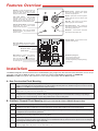
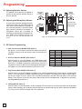
Faceplate: 18 guage 304 stainless steel or 16
gauge polished brass faceplate with super
durable UV stable powder paint to prevent
fading and resist scratching.
Speaker Screen: Stainless steel speaker
screen with 0.018" diameter holes to prevent
punctures from paperclips, etc.
Speaker: Mylar speaker with rubber gasket to
maintain water-tight seal and eliminate water
deterioration.
Color Video Camera:
Wide operating
temperature range of -30°F to 150°F, NTSC
composite video output with 420 lines of
resolution, 80° wide viewing angle lens, tilt and
swivel adjustments for aiming towards visitors.
Blue LED: Helps locate the push button,
indicate ringing and off-hook conditions.
Protective Camera Window: Impact resistant
polycarbonate lens with scratch resistant
coating and water-tight gasket.
Push Button Switch: Push to initiate call,
push again to disconnect. Solid 304 stainless
steel internally sealed per IP67.
Mounting Screws: 6-32 x 1.25" long flathead
with 5/64" hexdrive, 18-8 stainless steel to
prevent corrosion.
VIKING
Microphone:
Omni-directional microphone
with protective water-resistant cloth.
Faceplate Gasket: 1/8" thick closed cell PVC
to provide a water-tight seal.
Entry Phone Board: Compact analog speaker
phone with call progress detection for automatic
disconnect.
VIKING
DEV:
REN 0.8A: P/N: xxxxxx
Viking Electronics, Inc. (715) 386-8861
1531 Industrial St., Hudson, WI 54016
Complies with FCC Part 15 and 68 Reg. No: US:AH3TE08A22264
Speaker Volume
Model: XXXXXXX S/N: XXXXXXXX
Microphone Volume
Earth Ground: To increase surge protection,
loosen the screw labeled
(as shown) and
fasten a wire with ring terminal (included) from
the mounting screw to Earth Ground (grounding
rod, water pipe, etc.)
DIP Switches (see page 6):
1:
2:
3:
4:
Auto Answer Feature (on/off)
Dial Tone Detection (on/off)
Programming Switch (normal/programming)
LED (on/off)
Installation
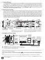
The E-65 is designed to be flush mounted into a standard double gang rough-in box with minimum inside dimensions of 2.25” deep x
3.65” wide x 2.84” tall. The E-65 can also be surface mounted in a Viking model VE-5x5 (not included, see DOD# 424).
WARNING: Do NOT use a typical “wet location box” as not all styles seal properly with the E-65 faceplate.
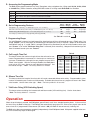
A. New Construction Flush Mounting
Step 1.
Recommended mounting height to bottom of the rough-in box is 50” - 54”. Front of box should stick out approximately ½" from front
surface of wall stud (this may vary depending on the walls sheathing and siding thickness). Caution: Rough-In box must be mounted
LEVEL and must NOT stick out beyond the front surface of siding.
Step 2.
To maintain a vapor barrier on outside wall applications, caulk around the box, filling any gaps between the box and the rough opening.
Apply caulk to any holes in the box around wires, etc.
Step 3.
When installing siding cut a hole just large enough for the Rough-In box opening. Caution: Too large of a hole can cause plate
misalignment and compromise the gasket seal. Note: A siding mounting block is recommended when mounting to vinyl siding or
siding with a 4” or less horizontal lap. Contact siding installer for the correct mounting block.
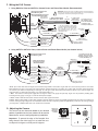
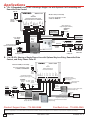
B. Old Work / Remodel Flush Mounting (Using a recommended Carlon BH234R Rough-In Box)
Step 1.
Recommended mounting height to bottom of the rough-in box is 50” - 54”. Make sure mounting location is free of wall studs, wires, etc.
Step 2.
Place Rough-In box LEVEL against siding. Trace outline of box onto siding. Note: A siding mounting block is recommended when
mounting to vinyl siding or siding with a 4” or less horizontal lap. Contact siding installer for the correct mounting block.
Step 3.
Cut a hole through the siding and wall sheathing just large enough for the rough-in box. Caution: Too large of a hole can cause plate
misalignment and compromise the gasket seal.
Step 4.
The front surface of the Rough-In box can be mounted flush against wood siding or can be recessed and mounted flush against wall
sheathing when mounting on aluminum, steel or vinyl siding.
Step 5.
When mounting to 5/8 inch thick or less wall sheathing the two attached screws with wing brackets can be used to secure the RoughIn box. When mounting to surfaces thicker than 5/8 inch, four standard flat head dry wall screws can be used to secure the Rough-In
box through its mounting ears (see page 4 section D).
Step 6.
To maintain a vapor barrier on outside wall applications, caulk around the box, filling any gaps between the box and the rough
opening. Apply caulk to any holes in the box around wires, etc.
3