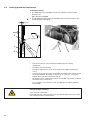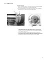
1
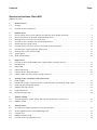
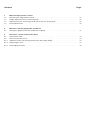
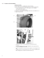
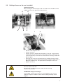
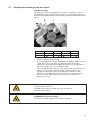
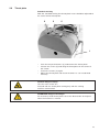
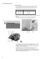
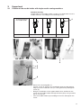
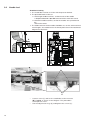
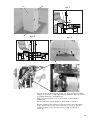
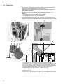
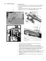
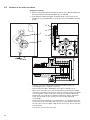
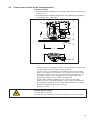
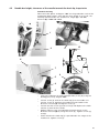
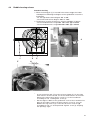
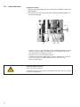
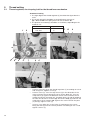
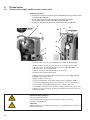
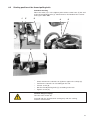
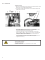
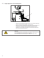
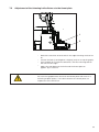
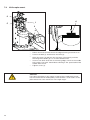
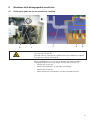
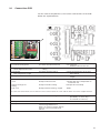
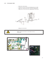
888
Service Instructions
All rights reserved.
Property of Dürkopp Adler AG and protected by copyright. Any reuse of these contents,
including extracts, is prohibited without the written approval in advance of Dürkopp Adler AG.
Copyright © Dürkopp Adler AG - 2012
Foreword
This instruction manual is intended to help the user to become familiar
with the machine and take advantage of its application possibilities in
accordance with the recommendations.
The instruction manual contains important information on how to
operate the machine securely, properly and economically. Observation
of the instructions eliminates danger, reduces costs for repair and
down-times, and increases the reliability and life of the machine.
The instruction manual is intended to complement existing national
accident prevention and environment protection regulations.
The instruction manual must always be available at the machine/sewing
unit.
The instruction manual must be read and applied by any person that is
authorized to work on the machine/sewing unit. This means:
–
–
–
Operation, including equipping, troubleshooting during the work
cycle, removing of fabric waste,
Service (maintenance, inspection, repair) and/or
Transport.
The user also has to assure that only authorized personnel work on the
machine.
The user is obliged to check the machine at least once per shift for
apparent damages and to immediatly report any changes (including the
performance in service), which impair the safety.
The user company must ensure that the machine is only operated in
perfect working order.
Never remove or disable any safety devices.
If safety devices need to be removed for equipping, repairing or
maintaining, the safety devices must be remounted directly after
completion of the maintenance and repair work.
Unauthorized modification of the machine rules out liability of the
manufacturer for damage resulting from this.
Observe all safety and danger recommendations on the machine/unit!
The yellow-and-black striped surfaces designate permanend danger
areas, eg danger of squashing, cutting, shearing or collision.
Besides the recommendations in this instruction manual also observe
the general safety and accident prevention regulations!
General safety instructions
The non-observance of the following safety instructions can cause
bodily injuries or damages to the machine.
1. The machine must only be commissioned in full knowledge of the
instruction book and operated by persons with appropriate training.
2. Before putting into service also read the safety rules and
instructions of the motor supplier.
3. The machine must be used only for the purpose intended. Use of
the machine without the safety devices is not permitted. Observe all
the relevant safety regulations.
4. When gauge parts are exchanged (e.g. needle, presser foot, needle
plate, feed dog and bobbin) when threading, when the workplace is
left, and during service work, the machine must be disconnected
from the mains by switching off the master switch or disconnecting
the mains plug.
5. Daily servicing work must be carried out only by appropriately
trained persons.
6. Repairs, conversion and special maintenance work must only be
carried out by technicians or persons with appropriate training.
7. For service or repair work on pneumatic systems, disconnect the
machine from the compressed air supply system (max. 7-10 bar).
Before disconnecting, reduce the pressure of the maintenance unit.
Exceptions to this are only adjustments and functions checks made
by appropriately trained technicians.
8. Work on the electrical equipment must be carried out only by
electricians or appropriately trained persons.
9. Work on parts and systems under electric current is not permitted,
except as specified in regulations DIN VDE 0105.
10. Conversion or changes to the machine must be authorized by us
and made only in adherence to all safety regulations.
11. For repairs, only replacement parts approved by us must be used.
12. Commissioning of the sewing head is prohibited until such time as
the entire sewing unit is found to comply with EC directives.
13. The line cord should be equipped with a country-specific mains
plug. This work must be carried out by appropriately trained
technicians (see paragraph 8).
It is absolutely necessary to respect the safety
instructions marked by these signs.
Danger of bodily injuries !
Please note also the general safety instructions.
Contents
Page:
Service instructions Class 888
(Edition 05/2012)
1
1.1
1.2
General notes
Gauges. . . . . . . . . . . . . . . . . . . . . . . . . . . . . . . . . . . . . . . . . . . . . . . . . . . . .
Position of the handwheel . . . . . . . . . . . . . . . . . . . . . . . . . . . . . . . . . . . . . . . . .
2
2.1
2.2
2.3
2.4
2.5
2.6
2.7
2.8
2.9
2.10
Bottom feed
Basic setting of the stitch adjustment and the stitch length limitation .
Stitch conformity of forward and backward stitch . . . . . . . . . . . . .
Setting of levers on the rear feed shaft . . . . . . . . . . . . . . . . . . .
Position of the eccentric for the feed movement . . . . . . . . . . . . . .
Switching of the feed clutch . . . . . . . . . . . . . . . . . . . . . . . . . .
Position of the eccentric for the switching of the feed clutch . . . . . .
Checking the switching of the feed clutch . . . . . . . . . . . . . . . . .
Setting of the semi stitch length . . . . . . . . . . . . . . . . . . . . . . .
Throat plate . . . . . . . . . . . . . . . . . . . . . . . . . . . . . . . . . . . .
Slide wheel feeder . . . . . . . . . . . . . . . . . . . . . . . . . . . . . . . .
.
.
.
.
.
.
.
.
.
.
.
.
.
.
.
.
.
.
.
.
.
.
.
.
.
.
.
.
.
.
.
.
.
.
.
.
.
.
.
.
.
.
.
.
.
.
.
.
.
.
.
.
.
.
.
.
.
.
.
.
.
.
.
.
.
.
.
.
.
.
.
.
.
.
.
.
.
.
.
.
.
.
.
.
.
.
.
.
.
.
.
.
.
.
.
.
.
.
.
.
.
.
.
.
.
.
.
.
.
.
.
.
.
.
.
.
.
.
.
.
.
.
.
.
.
.
.
.
.
.
.
.
.
.
.
.
.
.
.
.
7
8
9
10
11
12
13
14
15
16
3
3.1
3.2
3.3
3.4
3.5
3.6
Upper feed
Position of the needle holder with single needle sewing
Needle feed . . . . . . . . . . . . . . . . . . . . . . . . . . .
Roller foot . . . . . . . . . . . . . . . . . . . . . . . . . . . .
Roller foot lifting . . . . . . . . . . . . . . . . . . . . . . . .
Variator of the roller foot drive . . . . . . . . . . . . . . . .
Fabric holder for twin needle sewing machines . . . . .
machines .
. . . . . . .
. . . . . . .
. . . . . . .
. . . . . . .
. . . . . . .
.
.
.
.
.
.
.
.
.
.
.
.
.
.
.
.
.
.
.
.
.
.
.
.
.
.
.
.
.
.
.
.
.
.
.
.
.
.
.
.
.
.
.
.
.
.
.
.
.
.
.
.
.
.
.
.
.
.
.
.
.
.
.
.
.
.
.
.
.
.
.
.
.
.
.
.
.
.
.
.
.
.
.
.
17
18
20
21
22
23
4
4.1
4.2
4.3
4.4
4.5
4.6
Setting of the needle bar and of the hook
Hook height . . . . . . . . . . . . . . . . . . . . . . . . . . .
Needle bar height, clearance of the needle towards the
Hook tip guard and loop former . . . . . . . . . . . . . . .
Bobbin housing release . . . . . . . . . . . . . . . . . . . .
Hook lubrication . . . . . . . . . . . . . . . . . . . . . . . .
Shuttle plunger ring . . . . . . . . . . . . . . . . . . . . . .
. . . . . . . . .
hook tip, loop
. . . . . . . . .
. . . . . . . . .
. . . . . . . . .
. . . . . . . . .
. . . . .
stroke .
. . . . .
. . . . .
. . . . .
. . . . .
.
.
.
.
.
.
.
.
.
.
.
.
.
.
.
.
.
.
.
.
.
.
.
.
.
.
.
.
.
.
.
.
.
.
.
.
.
.
.
.
.
.
.
.
.
.
.
.
.
.
.
.
.
.
24
25
26
27
28
29
5
5.1
5.2
Thread setting
Thread regulator, check spring, bolt for the thread lever mechanism . . . . . . . . . . . . . . .
Bobbin winder . . . . . . . . . . . . . . . . . . . . . . . . . . . . . . . . . . . . . . . . . . . . . . . .
30
31
6
6.1
6.2
6.3
6.4
6.5
Thread cutter
Thread cutter height, position of the counter knife
Starting position of the thread-pulling knife. . . . .
Control cam . . . . . . . . . . . . . . . . . . . . . . . .
Bobbin thread clamp . . . . . . . . . . . . . . . . . .
Position of the throat plate insert . . . . . . . . . . .
32
33
34
35
36
.
.
.
.
.
.
.
.
.
.
.
.
.
.
.
.
.
.
.
.
.
.
.
.
.
.
.
.
.
.
.
.
.
.
.
.
.
.
.
.
.
.
.
.
.
.
.
.
.
.
.
.
.
.
.
.
.
.
.
.
.
.
.
.
.
.
.
.
.
.
.
.
.
.
.
.
.
.
.
.
.
.
.
.
.
.
.
.
.
.
.
.
.
.
.
.
.
.
.
.
.
.
.
.
.
.
.
.
.
.
.
.
.
.
.
.
.
.
.
.
.
.
.
.
.
.
.
.
.
.
.
.
.
.
.
.
.
.
.
.
.
.
5
6
Contents
Page:
7
7.1
7.2
7.3
7.4
Material edge trimmer control
Switching the edge trimmer on/off . . . . . . . .
Height adjustment of the trimming knife . . . .
Adjustment of the trimming knife distance from
Knife replacement . . . . . . . . . . . . . . . . . .
.
.
.
.
37
38
39
40
8
8.1
Machines with disengageable needle bar
Setting the guide bar for the needle bar coupling . . . . . . . . . . . . . . . . . . . . . . . . . . .
41
9
9.1
9.2
9.2.1
9.2.2
9.2.3
Electronic control and machine drive
Connections PCB . . . . . . . . . . . . . .
Direct Drive DAC classic . . . . . . . . . .
Important notes concerning electrostatic
Replacing the fuse . . . . . . . . . . . . . .
Exchanging the PCB . . . . . . . . . . . .
43
44
44
44
45
. . . . . . . . . .
. . . . . . . . . .
the throat plate
. . . . . . . . . .
. . . . . . . . . . . .
. . . . . . . . . . . .
discharges (ESD) .
. . . . . . . . . . . .
. . . . . . . . . . . .
.
.
.
.
.
.
.
.
.
.
.
.
.
.
.
.
.
.
.
.
.
.
.
.
.
.
.
.
.
.
.
.
.
.
.
.
.
.
.
.
.
.
.
.
.
.
.
.
.
.
.
.
.
.
.
.
.
.
.
.
.
.
.
.
.
.
.
.
.
.
.
.
.
.
.
.
.
.
.
.
.
.
.
.
.
.
.
.
.
.
.
.
.
.
.
.
.
.
.
.
.
.
.
.
.
.
.
.
.
.
.
.
.
.
.
.
.
.
.
.
.
.
.
.
.
.
.
.
.
.
.
.
.
.
.
.
.
.
.
.
.
.
.
.
.
.
.
.
.
.
.
.
.
.
.
.
.
.
.
.
.
.
.
.
.
.
.
.
1
General notes
This service manual describes the setting of the special sewing
machine class 888.
ATTENTION!
The operations described in the service instructions must only be
executed by qualified staff or correspondingly instructed persons
respectively!
Caution: Danger of injury !
In case of repair, alteration or maintenance work turn off the main
switch and disconnect the machine from the pneumatic supply
system.
Carry out adjusting operations and functional tests of the running
machine only under observation of all safety measures and with
utmost caution.
The present service instructions describes the setting of the sewing
machine in an appropriate sequence. Please observe in this
connection that various setting positions are interdependent.
Therefore it is absolutely necessary to carry out the settings by
following the described order.
For all setting operations of parts involved in the stitch formation a
new needle without damage has to be inserted.
Machine covers that need to be screwed off and on again for checking
and adjusting operations are not mentioned in the text.
Hint
Some of the shafts of the special sewing machine 888 are provided
with flat surfaces. This facilitates the setting considerably.
With all settings on flat surfaces always screw in the first screw on the
flat surface in the sense of rotation .
1.1
Gauges
The locking pin required for the machine setting belongs to the serial
equipment of the machine. It comes with the accessories and can be
kept at hand at the bottom side of the oil pan.
5
1.2
Position of the handwheel
Standard checking
The handwheel (4) has a graduation scale printed on.
Certain settings are effectuated through these handwheel positions.
– Turn the handwheel until the index (3) points to the degree
mentioned in this manual.
– Carry out the described setting.
The index (3) should point to the degree “0" when the needle bar is in
its upper dead position .
4
1
3
2
–
–
–
–
6
Loosen the screws of the handwheel using an Allen key of
3 mm (1).
Turn the needle bar to the upper dead point and set position (2)
using the locking pin (Æ 3 mm).
Turn the handwheel so that the index (3) points to the degree mark
“0”.
Tighten the first screw with the key (1), then turn the handwheel to
50° and tighten the second screw with the key (1).
2
Bottom feed
2.1
Basic setting of the stitch regulation and the stitch length limitation
Standard checking
1. When setting the stitch length to “0” the stitch regulator gear should
have the least clearance possible when the backtack lever is pushed
down.
2. The maximum stitch length is to be limited according to the sewing
category and the sewing equipment as described in the operating
manual.
5
3
6
4
1
2
–
–
Loosen screw (1) and pull off the setting wheel (2).
Turn screw (3) to the right using a 10 mm wrench and test the
clearance by pushing the backtack lever down until the stitch
regulator gear has no more clearance, so that rule 1 is observed.
–
–
Set the scale ring (4) with the stitch length “0” to the mark (5).
Limit the stitch length according to second rule. In order to do so
use the threaded pin (6) and screw it into the corresponding bore
hole. The bore holes have numbers that correspond to the
maximum stitch length.
If the maximum stitch length of 7 mm is required unscrew
screw (6) for about 2.5 mm. For this length exists another stop.
Attach the setting wheel (2) and tighten screw (1).
–
–
Caution: Danger of injury !
Turn the main switch off !
Proceed with the basic setting of stitch adjustment only with the
sewing machine switched off.
ATTENTION: Danger of breakage !
If the set stitch length is higher than the sewing equipment in use
allows, the needle will hit the throat plate insert.
7
2.2
Stitch conformity of forward and backward stitch
Standard checking
1. With a rough adjustment of the stitch regulator gear the machine should
not feed when the stitch length is set to “0”.
2. With a fine adjustment of the stitch regulator gear the stitch length of
the forward and backward stitch may not differ more than half a stitch
length.
2
1
–
–
–
–
–
–
8
5
3
6
4
Set the stitch length to “0”.
Loosen screw (1) and turn the eccentric (2) with its slot (3) as
shown in the diagram.
Fasten it with screw (1).
Loosen screw (4) of the clamping lever and turn the setting frame
(5) so that the fish plates (6) come parallel. Tighten screw (4). This
procedure accomplishes rule 1.
Then the stitch length of forward and backward stitches needs to
be compared. Sew 10 stitches forward, push the backtack lever
and sew 10 stitches backwared. Turn the eccentric (2) in order to
accomplish rule 2.
Clockwise direction
= forward stitch bigger, backward stitch
smaller,
Counter-clockwise
= forward stitches smaller, backward
stitches bigger
2.3
Setting of levers on the rear feed shaft
Standard checking
When setting the stitch length to “0“ the feed clutch should be in the
middle section of the operation end positions.
2
4
5
6
1
3
7
–
–
–
–
–
8
Set the stitch length to “0“.
Loosen screw (1).
Loosen screw (2) and pull out the bolt (3). The two screws found
underneath on the lever (4) must be fastened with an Allen key of
3 mm so that they sit on the flat surface of the shaft (5), mount the
bolt (3) again.
Unscrew the screw on the feed clutch (8) and push into the hole
the needle (7). Turn the clutch (8) manually until the needle sinks 5
mm into the bore hole. This procedure accomplishes the rule.
Tighten screw (1).
Caution: Danger of injury !
Turn the main switch off !
Set the basic setting of the levers only with the sewing
machine switched off.
ATTENTION: Danger of breakage !
If the middle section of the clutch is overstepped it can come to
collisions of parts inside the clutch when sewing with high stitch
lengths.
9
2.4
Position of the eccentric for the feed movement
Standard checking
When the index points to the degree mark “0” on the scale of the
handwheel, the feed lever (1) should not move when the backtack
lever is being pushed.
1
3
–
–
–
2
Turn the handwheel so that the the index points to the degree
mark “0” and arrest it by using the locking pin (see chapter 1).
Loosen screws (2) and turn the eccentric (3) for the rough
adjustment approximately into the position shown on the photo.
Now effectuate the fine adjustment until the position is found
where the feed lever (1) does not move when the backtack lever is
being pushed down.
Fasten the screws on the eccentric (3).
Caution: Danger of injury !
Turn the main switch off !
Set the basic setting of the eccentric only with the sewing
machine switched off.
ATTENTION: Danger of breakage !
Inaccurate settings shorten the machine’s life span.
10
2.5
Switching of the feed clutch
Standard checking
The clutch is to be switched when the clutch is motionless, that is in
the dead points of its oscillating movement.
4
1
–
–
–
–
–
5
2
6
3
Loosen screw (1) of the eccentric (2).
Turn the eccentric with line (2) against line (3).
Loosen the three screws (4) and the adjustment nut (5).
Fasten the adjustment nut (5) until it butts (the tightening torque
increases stepwise).
Push the clutch (6) to the right as far as possible and fasten the
screws (4).
Check the adjustment. Turn the eccentric manually in
counter-direction. The drag of the eccentric intensifies
considerably when the two lines form together one line.
Caution: Danger of injury !
Turn the main switch off !
Set the basic setting only with the sewing machine switched off.
.
ATTENTION: Danger of breakage !
Inaccurate settings shorten the machine’s life span.
11
2.6
Position of the eccentric for the switching of the feed clutch
Standard checking
When the index points to the degree “313" on the scale of the
handwheel, the line (1) on the eccentric should form one line with the
lower line (2) on the wedge pusher rod.
3
1
2
–
Loosen screw (3).
–
–
Set the handwheel to position “313”.
Turn the eccentric in the direction of the arrow until line (1) and
line (2) form one line.
–
Turn the eccentric about 2°back and push it along the axis
towards the shaft until the middle between the stop positions is
reached.
Align the lines (1) and (2) again to form one line and fasten
screw (3).
–
Caution: Danger of injury !
Turn the main switch off !
Set the basic setting only with the sewing machine switched off.
12
2.7
Checking the switching of the feed clutch
Standard checking
The clutch is to be switched when the clutch is motionless, that is in
the dead points of its oscillating movement. This can be recognized
through the turning direction of the pulley (1) before and after the dead
point.
B
A
1
1
2
3
4
274°
281°
94°
101°
B
–
Set the maximum stitch length.
–
Turn the handwheel until the index points to degree “274” (s. chart
/ A) on the scale. Push down the backtack lever and check
whether the turning direction (B) of the pulley (1) corresponds to
the chart. Do the same for the degree “281”.
If the turning directions do not correspond to the chart correct the
settings. If the clutch switches before (smaller angle) try this:
Loosen the adjustment nut (5) according to chapter 2.5 and
perform the mentioned check again until the correct position of
the nut is found. When the clutch switches later fasten the
adjustment nut (5).
–
Caution: Danger of injury !
Turn the main switch off !
Proceed with the basic setting only with the sewing
machine switched off.
ATTENTION: Danger of breakage !
Inaccurate settings shorten the machine’s life span.
13
2.8
Setting of the semi stitch length
Hint: This is an optional equipment.
Standard checking
When a semi stitch is selected by effectuating a push button, the
stitch length that is actually sewn should only be 50% of a 7 mm
stitch length and only 60%-70% of a 2 mm stitch length.
4
–
–
–
14
2
3
1
Loosen screw (1).
Turn the object (4) by setting the screw (3) with an Allen key of
2.5 mm (2) until the stitch length produced corresponds to the
rule.
Fasten screw (1).
2.9
Throat plate
Standard checking
With the standard setting the throat plate insert should be adjusted to
the center of the throat plate.
2
3
2
1
–
Push the two push buttons (1) and remove the throat plate.
–
Loosen the screws (2) and aling the throat plate in the center of
the cutout.
–
–
Fasten the screws (2) again.
Mount the throat plate and check whether it is set in and fixed
correctly.
Caution: Danger of injury !
Turn the main switch off !
Proceed with the throat plate setting only with the sewing
machine switched off.
ATTENTION: Danger of breakage !
An incorrectly fixed throat plate causes the destruction of the parts
when the machine is started.
15
2.10 Slide wheel feeder
Standard checking
1. The height (A) of the wheel feeder above the throat plate must be
adjusted according to the thickness and rigidity of the material.
2. Standard height of teeth above the throat plate insert see chart:
Needle thickness Nm
70 - 80
90 - 110
120 - 200
Height of the wheel feeder (A)
0,4 - 0,5
0,4 - 0,5
0,6 - 0,8
A
3. Also the tooth pitch must be adapted according to the material that is to
be sewn:
thin material – fine teeth in order to avoid marks in the leather
soft, thick material – thick teeth for sufficient feed traction
4
5
1
16
2
3
–
Set the height of the wheel feeder (5) according to rule 2. Loosen
screw (2) by using an Allen key (3) and retighten the screw (1).
After reaching the desired height first tighten screw (2) and then
retighten screw (1) once again.
–
In order to lower the wheel feeder, loosen screw (1) and then
retighten screw (2). Then the sequence is inversed.
–
When exchanging the wheel (5) take out the throat plate (see
chapter 2.9). Push the slide (4) with the wheel feeder (5) upwards.
Exchange the wheel feeder according to rule 3 and remount the
parts in inversed sequence again.
3.
Upper feed
3.1
Position of the needle holder with single needle sewing machines
Standard checking
The position of the needle holder is to be set in dependance to the
needle thickness according to the folllowing chart.
Angular position of
the needle holder
3
Needle thickness Nm
70 - 110
1
120 - 160
180 - 200
2
5
4
6
–
–
–
–
Remove the thread guide (1).
Loosen screw (2) and turn the needle bar with the right groove
edge (3) to the needle bar axis (in sewing direction) and tighten
screw (2).
Bring the needle bar to the upper dead center and loosen the
screw of the needle holder through the bore (4) by using an Allen
key of 2.5 mm (5).
Turn the needle holder (6) according to the rule and tighten the
screw.
17
3.2
Needle feed
Standard checking
1. The needle bar must be set in line with the presser foot bar.
2. The post bed feed is to be set
2.1 with single needle machines, so that the axis of the needle
is displaced about A = 0,1 mm to the left of the stitch hole center.
2.2 with twin needle machines, so that the needles are symmetrical to
the
stitch hole centers.
3. The feed movement of the needle should be set, so that, with maximum
stitch lengths, the needle leaves the throat plate close to the backward
edge of the stitch hole
A
B
1
2
–
–
18
Loosen screw (1) and set the needle bar to the measure
(B) = 31mm as shown in the diagram. This procedure
accomplishes rule 1.
Set the adjustment rings (2) and tighten the screws (1).
5
3
fig. 1
A
4
fig. 2
fig. 3
6
–
–
–
–
Loosen screw (3) and the two screws (4). Displace the post bed
feed (5) so that rule 2.1 (A) = 0,1 mm according to fig. 1 or rule 2.2
according to fig. 2 is accomplished.
Adjust the throat plate insert to the center as described in
chapter 2.9.
Set the maximum stitch length as described in chapter 2.
Set the needle to the position in which it leaves the throat plate
insert. Dismantle the rear cover and loosen screw (6). Set the
needle manually to the position shown in fig. 3 and tighten
screw (6).
19
3.3
Roller foot
Standard checking
1. The location surface on the roller foot holder should be aligned in the
right angle to the longitudinal axis of the machine .
Between the roller foot and the wheel feeder should be a distance of
(A) = 0,03 to 0,16 mm.
2. The position of the roller foot in sewing direction should be set as
follows:
- for single needle machines (B) = 1,3 to 2,3 mm
- for twin needle machines (B) = 0 to 2,3 mm
3. The lateral position of the roller foot should be set so that the lower
edge of the roller foot ends with the left-hand edge of the stitch hole (8).
1
6
4
2
8
7
A
A
5
3
B
–
–
–
20
Loosen screw (1). Displace the presser foot bar vertically
according to rule 1. Insert the Philips screw-driver (2) that is part
of the accessories into the hole of the roller foot holder (3) and
turn the presser foot bar (4) together with the roller foot holder (3)
until the Philips screw-driver comes to a right angle with the
longitudinal axis of the machine. Tighten screw (1).
Loosen screw (5). Displace the roller foot according to rule 2 and
tighten screw (5).
Loosen screw (6). Displace the roller foot according to rule 3 with
the adjusting screw (7) and tighten screw (6).
3.4
Roller foot lifting
Standard checking
1. The lifting of the roller foot via hand lever should be of 5.4 to 5.6 mm.
2. The lifting of the roller foot via electromagnet should be of 11.5 to
12.5 mm.
3. The lifting of the roller foot via knee lever should be of about 0.2 to
0.4 mm higher than the electromagnetic lifting (if existing).
3
1
2
4
3
1
6
7
5
–
–
–
–
–
Dismount the head cover, upper arm cover and solenoid (if
existing) of the presser foot lifting.
Loosen screw (1). Bring the hand lever (2) into the depicted
position and simultaneously screw in screw (3) until it butts
against the lever (4). The lever (2) remains in the depicted position.
Put a spacer of 5.6 mm underneath the roller foot and push the
lever (5) manually according to the figure above until it stops.
Tighten screw (1). This procedure accomplishes rule 1.
Remove screw (3) and mount the electromagnet of the presser foot
lifting (6). In order to check whether rule 2 is accomplished,
engage the magnetic core. If the values are not correct, effectuate
an adjustment.
Set the lifting of the knee lever according to rule 3 by adjusting
screw (3).
21
3.5
Variator of the roller foot drive
Standard checking
1. With the correct position of the belt tensioner (1) the distance between
the two cords of the V-belt should be (A) = 1 to 2 mm.
2. If the difference between upper and lower feed is set to zero on the
setting nut (3), the graduation scale on the nut (4) should point exactly
to “O”.
5
4
1
3
2
B
A
–
Loosen screw (2) and position the belt tensioner roller (1)
according to rule 1. Tighten screw (2).
–
–
Set the diameter (B) = 34 mm by turning the setting nut (3).
Make sure that there is no material displacement between upper
and lower feed. Sew two narrow strips of sewing material of about
30 cm together. If the strips after sewing are vaulted upward or
downward, this indicates a difference between upper and lower
feed. The position of the setting nut (3) must be adjusted
accordingly.
After reaching the point of “zero difference”, the graduation scale
on the nut (4) must be adjusted. Turn the nut (4) until the third line
of the scale is on the upper edge of the the nut (3). This marks the
zero position.
Secure the nut (4) with screw (5).
–
–
22
3.6
Fabric holder for twin needle sewing machines
Standard checking
1. The fabric holder should touch the sewing material without exerting any
pressure on it.
2. The fabric holder should be positioned in sewing direction and laterally
on the edges of the stitch holes.
4
7
1
2
5
6
3
6
–
–
–
–
Insert two pieces of leather of about 1.5 mm thickness underneath
the roller foot and set a medium fabric pressure.
Loosen screw (1) and displace the holder (2) with the rear fabric
holder (3) vertically until it comes to rest without any pressure on
the leather. Tighten screw (1), but not too hard. Loosen screw (4)
and effectuate the same setting for the front fabric holder (5).
Remove the leather, rule 1 is now accomplished.
Set the fabric holder according to rule 2: Set the rear fabric
holder (3) to the sewing direction by using screw (6) and laterally
by turning the holder (2). Set the front fabric holder to the sewing
direction and laterally by using screw (7).
Tighten all screws.
Caution: Danger of injury !
Turn the main switch off.
Proceed with the setting only with the sewing machine switched off.
23
4
Setting of the needle bar and of the hook
4.1
Hook height
Standard checking
The distance A should be 1.55 up to 1.85 mm.
A
2
1
3
–
Loosen screw (1).
–
Loosen screws (2), shift the hook at the distance A and tighten the
screws (2).
Push the ring (3) until its stops at the the hook bottom and tighten
screw (1). When replacing the hook, it is not necessary to readjust
its setting in height again.
–
Caution: Danger of injury !
Turn the main switch off.
Proceed with the hook setting only with the sewing machine switched
off.
24
4.2
Needle bar height, clearance of the needle towards the hook tip, loop stroke
Standard checking
When the index points to degree “ 203” on the graduation scale of the
handwheel (loop stroke 2 mm) and the stitch length is set to “0”, the
hook tip should stand in the needle axis, length (A) = 1.5 mm,
distance (B) = 0.02 to 0.1 mm.
1
B
4
2
6
7
3
5
8
5
–
–
–
–
–
–
Lock the handwheel in loop stroke position (2 mm) by using the
locking pin (5 mm), degree “203”.
Loosen screw (2) and turn the hook tip (3) to the needle axis.
Loosen screw (4), position the needle bar and needle to the
distance measure (A) and tighten screw (4).
Loosen the two screws (5) and screw (6) and displace the hook
column (7) from off the needle.
Slightly tighten screw (5) and bring the hook column to the
distance measure (B) by using the screw (8). Tighten screws (5)
and (6).
Check whether the hook tip (3) is positioned in the range of the
needle axis, tighten screw (2).
25
4.3
Hook tip guard and loop former
Standard checking
A
1. The loop former (1) should be set to have a distance to the needle
thinkness of
(A) = 0.1 up to 0.2 mm.
2. The guard plate of the hook (3) should prevent a contact between the
needle and the hook tip (4).
4
1
3
2
–
–
–
–
–
–
4
Set the maximum stitch length according to the sewing
equipment.
Dismount the throat plate.
Bend the loop former (1) to have the distance (A) according to
rule 1.
Position the hook tip (4) on the needle and adjust the setting screw
of the guard plate by using an Allen key of 3 mm (2), so that the
needle does not touch the hook tip (4).
Checking: Exert a light pressure on the needle (see arrow) and turn
the hook at the same time.
The setting is not incorrect if the guard plate (3) slightly deflects
the needle.
Caution: Danger of injury !
Turn the main switch off.
Proceed with the setting of the hook guard and loop former only with
the sewing machine switched off.
26
4.4
Bobbin housing release
Standard checking
1. When the locking pin (1) is inserted in the release trigger, the index
should point to following the degrees on the graduation scale of the
handwheel:
- for the right hook column degree “45” to “50”
- for the left hook column degree “140” to “145”.
2. The distance measure (A) with max. release should be as follows:
- for the needle thickness range Nm 70 to 110 - (A) = 0.5 mm
- for the needle thickness range Nm 120 to 200 - (A) = 0.8 mm
4
1
5
2
3
A
–
Insert the locking pin (1) into the release trigger (2). On the right
hook column at the rearside, on the left hook column at the front.
Remove the lower plug, loosen screw (3), set the handwheel
according to rule 1 and tighten screw (3).
–
Set the degree “310” on the graduation scale of the handwheel to
point to the index, remove the plug, loosen screw (4), turn the
bobbin housing release (5) so that the distance measure (A)
according to rule 2 is accomplished. Tighten screw (4) and plug
the openings again.
27
4.5
Hook lubrication
Standard checking
A
1. Between the lubricating fitting (2) and the hook should be a distance of
(A) = 0.3 mm.
2. The setting screw (3) of the lubrication should proceed 0.5 mm out of
the lubricating fitting.
1
–
–
–
3
2
Loosen screw (1), set the height of the lubricating fitting (2) to the
distance measure (A) according to rule 1 and tighten screw (1).
This procedure accomplishes rule 1.
Screw in screw (3) according to rule 2.
In order to throttle the lubrication, screw in deeper the screw (3),
but not any further than 0.5 mm below the surface of the
lubricating fitting (2).
Caution: Danger of injury !
Turn the main switch off.
Proceed with the setting of the hook lubrication only with the sewing
machine switched off.
28
4.6
Shuttle plunger ring
Standard checking
With the sewing equipment for light-weight material (needle thickness
Nm 70 to 80) a shuttle plunger ring with spur should be used.
1
–
–
2
Dismount the shuttle plunger ring (1).
Mount the shuttle plunger ring with spur (2) that is part of a
complete sewing equipment.
Caution: Danger of injury !
Turn the main switch off.
Exchange the shuttle plunger ring only with the sewing
machine switched off.
29
5
Thread setting
5.1
Thread regulator, check spring, bolt for the thread lever mechanism
Standard checking
2
A
1
1. The right edge of the thread regulator (1) should end at figure 2 on the
scale.
2. The check spring (5) should be set to the distance measure of
(A) = 10 to 12 mm. The spring travel consists of about 30°.
3. The position of the bolt (8) should be set as follows, depending on the
needle in use:
Needle thickness Nm Bolt position
70-110
B
7 B
8
120-200
C
5
6
4
3
8
7
–
–
–
30
C
Loosen screw (2), push the thread regulator (1) according to rule to
end at figure 2, tighten screw (2).
Loosen screw (3). Turn the stop sleeve (4) in the direction of the
arrow until the check spring (5) comes off the body (6). Turn the
stop sleeve (4) against the direction of the arrow until the check
spring (5) touches the body (6). Turn both parts (4) and (6) together
to reach the distance measure (A). Detain the body (6) and turn the
stop sleeve (4) for another 30° against the arrow. Detain the parts
(4) and (6), tighten screw (3).
Insert a 3 mm Allen key in the holes (7) and loosen the screws.
Bring the bolt (8) into the correct position according to rule 3 and
tighten screws (7).
5.2
Bobbin winder
Standard checking
1. When the bobbin winder is switched off, the distance between bobbin
winder wheel and belt pulley should be (A) = 0.8 mm.
2. The winding procedure should stop automatically, when the bobbin is
filled up to 0.5 mm underneath the the bobbin edge.
A
1
2
–
–
Turn the belt pulley to the top using the screws (1). Push the
toothed belt to the right so that both screws (1) are accessible.
Loosen screws (1) and set the distance measure (A) according to
rule 1, tighten screws (1).
Determine the bobbin filling by adjusting screw (2). Screw in
screw (2) for 1 to 2 mm, but a bobbin on the bobbin winder shaft
and wind on thread. Check the filling when the winder switches off
and adjust the position of screw (2) until rule 2 is fulfilled.
31
6.
Thread cutter
6.1
Thread cutter height, position of the counter knife
Standard checking
1. The distance measure between the thread-pulling knife (5) and the hook
should be (A) = 0.2 mm.
2. The distance measure between the counter knife (6) and the
thread-pulling knife (5) should be (B) = 0.3 to 0.5 mm.
3. The knives should have contact at the distance (C) = 1 to 2 mm.
6
C
A
B
5
5
3
3
4
2
1
–
–
Loosen screws (1), (2), (3) and push the holder (4) downwards.
Slightly tighten screw (2), that sits on the surface of the shaft.
–
Tighten screw (3) until the distance measure (A) = 0.2 mm is set
and thus rule 1 is accomplished.
Tighten screw (2) and afterwards also screw (1).
Dismount the column protection.
–
–
–
–
–
–
–
Loosen screws (3) and (4). Set the distance measure (B) = 0.3 to
0.5 mm according to rule 2.
Slightly tighten screw (4).
Turn the handwheel, so that the index points to degree “270” .
Turn the thread-pulling knife (5) manually to set it to the distance
measure (C) = 1 to 2 mm and adjust the counter knife (6)
accordingly until the knives touch smoothly (without any pressure).
Tighten screws (3) and (4) and check whether the knives touch at
the distance (C).
Caution: Danger of injury !
Turn the main switch off.
Proceed with the thread cutter setting only with the sewing
machine switched off.
Attention!
When the pressure of the counter knife is set too high this results in a
higher knife wear
32
6.2
Starting position of the thread-pulling knife
Standard checking
When the roller (1) is in the highest point of the control cam (2) the end
of the thread-pulling knife (3) should overrun the blade of the counter
knife (4) of 0.5-1 mm.
1
5
2
4
3
6
–
–
–
–
–
Check whether the control cam (2) butts against the circlip (5).
Position the control cam according to the rule.
Loosen screw (6).
Set the thread-pulling knife (3) according to the rule.
Tighten screw (6).
Caution: Danger of injury !
Turn the main switch off.
Proceed with the thread cutter setting only with the sewing
machine switched off.
33
6.3
Control cam
Standard checking
1. Between the highest point of the control cam (1) and the roller (2) should
be a distance mesure of (A) = 0.05 to 0.1 mm.
2. The threads should be separated when on the handwheel degree “40”
to “45” points to the index.
2
A
3
–
–
–
–
1
4
5
Loosen the counter nut, turn screw (3) until the distance
(A) = 0.05 to 0.1 mm according to rule 1 is set between the roller
(2) and the highest point of the control cam (1).
Loosen the two screws (4). Set the handwheel until the index
points to degree “40” to “45” on the scale. Set the thread-pulling
knife (5) manually so that the blade of the thread-pulling knife
overlaps the blade of the counter knife.
Push the control cam (1) to the left and at the same time turn it in
the turning direction of the machine until roller (2) butts.
Tighten the screws (4).
Caution: Danger of injury !
Turn the main switch off.
Proceed with the control cam setting only with the sewing
machine switched off.
34
6
6.4
Bobbin thread clamp
Standard checking
The clamping effect of the spring (1) should not be set stronger than
the strength needed to pull out the bobbin thread of the hook.
1
3
2
–
–
–
Sew and cut the threads.
Check with a screw driver (2) as shown in the figure whether the
thread is pulled out of the bobbin or out of the clamp (1).
Adjust the clamping effect of the spring (1) with screw (3) until the
rule is accomplished.
Caution: Danger of injury !
Turn the main switch off.
Proceed with the clamp spring setting only with the sewing
machine switched off.
Attention!
A wrong setting of the clamp spring can lead to problems at the seam
beginning.
35
6.5
Position of the throat plate insert
Standard checking
When sewing with a short stitch, the throat plate insert should be
pushed aside towards the operator in order to avoid a missed stitch at
the seam beginning.
2
1
–
–
–
Set the stitch length to 1.5 to 2.5 mm depending on the thread
size.
Check whether at the seam beginning missed stitches occur. If
this is the case, push the throat plate insert (1) into the direction of
the arrow until the rear edge of the stitch hole (2) has a distance of
0.2 to 0.3 mm to the needle. Screw the throat plate insert on
again.
Limit the stitch length to 2.5 mm. The rule of the stitch length
limitation is described in chapter 2.1.
Caution: Danger of injury !
If the position of the throat plate insert has been altered and the stitch
length is not limited to 2.5 mm, the needle will hit the throat plate
insert with higher stitch lengths and needle breakage will occur. At the
same time the operating personnel will suffer injury.
36
7
Material edge trimmer control
7.1
Switching the edge trimmer on/off
3
5
B
4
2
1
1
A
Switch on
– Push the knob (1) in the direction of the arrow (A) or pull the
handle (2) in the direction of the arrow (B) until the trimming knife
moves from its initial position (3) to the trimming position (4).
– The edge trimming mechanism is started automatically when
switched on, and the trimming knife starts oscillating. While
sewing trimming (e.g. a lining) is effectuated simultaneously.
– When trimming edges, direct the trimmed material to come
underneath the knife collar (5).
Switch off
– Push the knob (1) downwards. The trimming knife turns from the
trimming position (4) to the initial position (3) and the edge
trimming mechanism switches off automatically.
37
Height adjustment of the trimming knife
A
7.2
1
–
–
Adjust the trimming knife height with the nut (1). When tightening
the nut, the knife shifts upwards, and vice versa.
Adjust it in a way that the gap (A) corresponds to the thickness of
the material to be trimmed. If the material is thicker in some
section (e.g. at sections where two parts of lining are sewn
together), the trimming knife height is automatically adjusted to
the increased material thickness .
Attention!
If the trimming knife is set too high, its cut will be of poor quality and
will also damage the upper layer of the material.
If the trimming knife is set too high, the edge trimming is noisy.
38
7.3
Adjustment of the trimming knife distance to the throat plate
A
1
2
–
–
–
–
Switch the machine off and switch the edge trimming mechanism
on.
Loosen the bolt (1) and tighten it slightly (only to set up the gap A).
Turn the bolt (2) in clockwise direction, shift the trimming bolt to
the left or to the right.
Adjust the gap between the knife and the throat plate to
approx. (A) = 0.05 mm.
Attention!
An excessive gap between the knife and throat plate will result in a
trimming of poor quality. If the knife touches the throat plate, an
unpleasant noise will occur.
39
7.4
Knife replacement
2
1
5
6
3
4
–
–
–
–
–
Switch the knife off and switch the edge trimming mechanism on.
Loosen the bolt (1) and remove the knife (2).
Open the cover (3) and turn the eccentric (4) manually until the
trimming knife holder (5) is in its front dead center.
Insert a new knife and, with its trimming edge, shift it to the needle
hole center. The knife should be oscillating in the space behind the
needle hole center.
Tighten screw (1).
Attention!
If the knife oscillates in the space in front of the needle hole center,
the trimmed material will be poorly trimmed with a small radius in the
point where the seam continues in the right angle .
40
8
Machines with disengageable needle bar
8.1
Setting the guide bar for the needle bar coupling
2
1
1
4
3
Caution: Danger of injury !
Turn the main switch off.
Proceed with the setting of the guide bar for the needle bar coupling
only with the sewing switched off.
Set the guide bar (1) in a way that at position zero (both needles
engaged) the pivot centre (4) stands exactly above the pin (3).
– Loosen the screws (2).
– Correct the guide bar’s (1) position accordingly.
– Tighten the screws (2).
– Check whether the needle bars can be switched correctly.
41
9
Electronic control and machine drive
Detailed operating instructions of the positioning drive are enclosed
with the sewing machine.
A selection of instructions concerning the controlling and adjustments
of the drive, accessible to the operator, are included in the operating
instructions.
A selection of instructions needed for the setting of the drive,
provided for the technician, are included in operating instructions.
The operating instructions of the positioning drive are enclosed with
the sewing machine (see also www.efka.net).
42
9.1
Connections PCB
For the sake of completeness, the various connections of the PCB
below are explained here.
X11 Control Sewing Drive
X12 Solenoid Thread Tension
X13 Solenoid
Additional Thread Tension
X14 Solenoid
Stroke Adjustment Pneum.
X15 Solenoid Sewing Foot
Lifting
X16 Solenoid Tack
X17 Solenoid
Switching Stitch Length
X18 Solenoid Short Stitch
X19 HP-Potentiometer in the Arm
(Speedomat)
X20 Key Block
X21 Light Barrier Seam End
X23 Speed Limitation Stitch
Length
X22
1 +24V
2 Output Thread Cutter
5 Output Needle Cooling
3 Output Flip-flop 3 Adjustable via
Parameter 275
6 Output Thread Clamp
9 Output Motor Running / Signal
10 0V
4 Output Sewing Foot
Lifting
7 u. 8 +24V
For each connection make sure to have one wire connected to the +24V and the other one to the output function.
X24 Residual Thread Monitor
X25 Oil Level Monitoring
X26 Input Machine Run Blockage
(Possibility of connecting
an external ext. PIN 2/3)
X27 Output for max. 50 mA
J2 Jumper 2
Closed: bridging the input machine
run blockage X26 PIN 2/3
Open: an external “trigger” button
must be connected to the X26
PIN 2/3.
43
9.2
9.2.1
Direct Drive DAC classic
Important notes concerning electrostatic discharges (ESD)
ATTENTION
Before effectuating any works on electronic components:
Turn off the main switch. Remove the plug from the socket.
·
·
·
9.2.2
Electrostatic discharges can cause damage to PCBs and other
components.
You can obtain a certain protection by wearing anti-static gloves
or wrist-wraps that you can connect for grounding on the mass of
any unpainted metal piece of the machine head or on the switch
cabinet.
Handle the PCBs with utmost caution. They are very sensitive
towards electrostatic discharges.
Hold the PCBs only at their edges.
Put the PCBs after unwrapping or after dismounting with their
components upside onto a grounded statically discharged
surface. We recommend to use a conductive foam underlay but
not the protective cover of the PCB.
·
Pay attention not to pull the PCB over any surface.
–
–
Exchange the fuse (1)
The fuse serves only for the integrated sewing light transformer.
Recplacing the fuse
Value: 0,63 A T
44
9.2.3
Exchanging the PCB
–
–
–
–
Remove the connectors.
Loosen the screws (1) for the holding plate of the PCB.
Replace the PCB (2) and refix it onto the holding plate.
Tighten the screws (1) for the holding plate on the PCB.
2
1
–
Replug the connectors.
Caution !
Make sure that the motor is connected correctly!
(see photo)
45
Notes:
46
Subject to design changes - Printed in Germany - © Dürkopp Adler AG - 0791 888651 - 00.0 - EN - 05/2012
DÜRKOPP ADLER AG
Potsdamer Str. 190
33719 Bielefeld
Germany
Phone +49 (0) 521 925 00
E-Mail: [email protected]
www.duerkopp-adler.com