1
CONTENTS
SPECIFICATIONS ....................................................................................................................................... 1
BLOCK DIAGRAM ...................................................................................................................................... 3
ADJUSTMENT ............................................................................................................................................ 4
■ Preparation .......................................................................................................................................... 4
1. PROGRAM LOADING .......................................................................................................................... 5
1-1. Important notice ............................................................................................................................ 5
1-2. To load the program ..................................................................................................................... 5
2. Program version upgrading .............................................................................................................. 7
2-1. How to confirm the program (graphic menu) version .............................................................. 7
2-2. Upgrading using CF card ............................................................................................................ 8
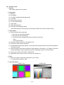
3. Test mode ........................................................................................................................................... 9
3-1. Booting ......................................................................................................................................... 9
3-2. Item for testing ............................................................................................................................. 9
4. Adjustment ....................................................................................................................................... 11
4-1. Color adjustment data writing .................................................................................................. 11
4-1-1. Note ...................................................................................................................................... 11
4-1-2. The example which must be adjusted .............................................................................. 11
4-1-3. To replace the lens ass'y ................................................................................................... 11
4-1-4. To replace CMD-PCB .......................................................................................................... 13
4-2. Flash adjustment ....................................................................................................................... 15
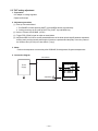
4-3. Flash operation and recharge operation ................................................................................. 16
4-4. Current consumption ................................................................................................................ 17
4-5. VCOM DC adjustment ................................................................................................................ 18
4-6. Operation check ......................................................................................................................... 20
5. D-PCB Assy ...................................................................................................................................... 21
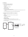
5-1. VCO free run frequency adjustment ........................................................................... 21
5-2. VCOM AC adjustment and VCOM DC coarse adjustment ........................................ 21
5-3. RGB AMP and Sub-Brightness voltage setting adjustment ..................................... 22
5-4. Contrast and Brightness voltage setting adjustment ............................................... 23
5-5. TINT setting adjustment ............................................................................................... 24
6. PW-PCB Assy ................................................................................................................................... 25
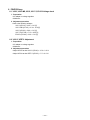
6-1. VCC3, VCC3-MD, VCC5, VCC7.5, EVCC3 Voltage check .......................................... 25
6-2. VCC15, VEE7.5 Adjustment ......................................................................................... 25
DISASSEMBLY/ASSEMBLY .................................................................................................................... 26
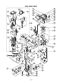
EXPLODED VIEW ..................................................................................................................................... 36
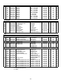
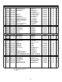
PARTS LIST .............................................................................................................................................. 37
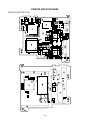
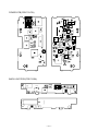
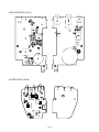
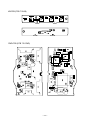
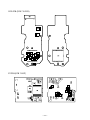
PRINTED CIRCUIT BOARDS ................................................................................................................... 40
SCHEMATIC DIAGRAMS ......................................................................................................................... 45