1
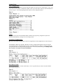
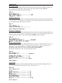
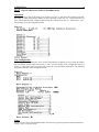
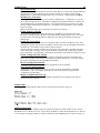
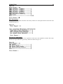
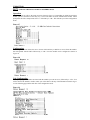
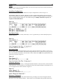
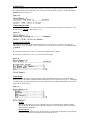
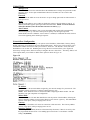
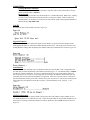
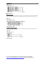
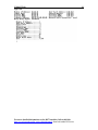
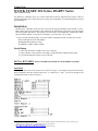
U140A135-00
1
QUICK START: DS Series, DS-RPC Series
by Bay Technical Associates
The DS-Series or DS-RPC Series is a console control data switch for applications that require control of
multiple peripherals from a single host such as remote site management, out-of-band management, general
data switching, etc.
Installation
The DS Series or DS-RPC Series base units come with optional input modules such as the DS 71, DS71MD3, DS62, DS72, DS73 and DS74. This manual will be divided into sections that go into brief detail
about each product listed above. The samples used for the below is the DS4D-RPC, with the DS71-MD3,
DS72 and DS74 modules. The actual screen displays of your unit may vary by model.
Remove the DS from the package. Check the contents of shipment to make sure that you received:
DS or DS-RPC base unit with modules.
RJ08X007 (RJ45 Rollover Cable)
9FRJ45PC-4 (DB-9 to RJ45 Adapter)
Serial Setup
• Connect the 9FRJ45PC-4 adapter to the user’s computer.
• Connect the RPC’s EIA-232 port to the adapter via the RJ08X007 rolled flat ribbon cable.
• Use terminal emulation software to access the unit.1
DS71 or DS71-MD3 - RS232
and Modem host module for the DS SERIES or DS-RPC
Series chassis.
Operation
Once connected you will see the menu screen as shown in Figure 1. This shows the operation of the unit.
When prompted at the unit’s startup menu select “C” followed by a <CR>.2 You will be brought to the
Configuration menu As shown in Figure 2.
Figure 1
Figure 2
1
Any type of Terminal Emulation software can be used, like Windows HyperTerminal, Reflections, Procom, etc with a port
configuration set to 9600, 8, none, 1. This manual uses Tera Term found at
http://hp.vector.co.jp/authors/VA002416/ttermp23.zip.
2
<CR> = HRT or ENTER. This can also take you back to the previous screen.
U140A135-00
Unit Configuration
2
At the prompt, type the number associated with the module you want to access, followed by a <CR>. You
will be taken to the module’s configuration window where you will be able to edit any of the information as
shown in Figure 3. The following pages define each line of the configuration menu.
Figure 3
Status
Used to view the status of the installed modules, modem setup, login setup, assigned user ports and
associated information by issuing a series of carriage returns.
Serial Port Configuration
DS-Series host modules translate data for devices using different serial configurations as shown in Figure
4.
The Baud Rate, Word Size, Stop Bits, and Parity can all be configured through the serial port using the
self-explaining menus. Xon/Xoff, RTS Line Driver, and DTR Line Driver cannot be configured using the
serial port; they must be configured using the phone line. The factory default settings are 9600bps, 8 data
bits, no parity, one stop bit, Xon/Xoff and DTR low.
Figure 4
Port Device Name
Select the port you want to rename, followed by a <CR>. Type the name you want to associate with the
port as shown in Figure 5.
Figure 5
U140A135-00
Port Select Code
3
The Port Select Code is an ASCII character string sent by the host terminal to the module to select an I/O
port on a DS74 peripheral module. The Port Select Code’s factory default setting is $BT and is
programmable up to 8 characters as shown in Figure 6.
Figure 6
Attention Character
Attention Character = semi-colon (;). Pressing the attention character 5 consecutive times will return back
to the main menu. This menu allows you to change the value of the attention character for the DS series, so
as not to negate the access menu as shown in Figure 7.
Figure 7
Disconnect Timeguard
This feature provides reliable binary data transmission by providing a one-second “timeguard” after the DS
Series receives the attention character, eliminating port disconnection. The Timeguard will disconnect your
session if you have been idle too long. Factory default is disabled as shown in Figure 8.
Figure 8
Connect Port ID Echo
This option allows you to enable or disable the Port ID echo. The echo is a feature that allows you to view
the port ID when you log onto the port. To change; select 8 followed by a <CR>. To enable select Y
followed by a <CR> as shown in Figure 9. The factory default setting is disabled.
By selecting 2 followed by a <CR>, you can echo the module and port number.
By selecting 3 followed by a <CR>, you can echo the device name.
Figure 9
Login Setup
This menu allows the user to enable or disable the Header, Access Control, Menu, Manage Users, Auto
Connect, Dial Back Number, and Assign User Ports. Shown in Figure 10.
Figure 10
U140A135-00
4
Header
This allows the user to have limited control over the Header, either enable or disable option to
display the Header upon connection to the host module. NOTE: The header may appear
different depending on the type of module installed.
Access Control
This will allow you to access the menu where you can modify such options as prompting for
usernames and passwords for both network and serial port access.
Menu
This allows user to enable or disable the Menu on start up. If disabled, the header appears upon
login without the main menu. NOTE: To invoke the main menu when disabled, enter the
attention character five times (;;;;;).
Manage Users
This will allow access to the menu that allows the administrator to change user passwords or add
new users. Up to 19 users plus an administrator allowed. Usernames are case sensitive and
alphanumeric.
Auto Connect
This feature allows users to select the DS74 module and port that will be automatically connected
on power up. The auto connect port has priority over the login setup menu enable/disable
selection. When the ‘Auto Connect” is enabled, the header and main menu is automatically
disabled.
Dial Back Number
This allows user to dial a number, hang up and call the number back when using a secure phone
line.
Assign User Ports
This allows the administrator to limit users’ port access.
Local Modem Setup
This allows the user to change the Rings to Answer, Connectivity Time-Out and Escape Character,
Modem-to-Modem XON/XOFF setting, as shown in Figure 11.
Figure 11
Rings to Answer
This allows the user to change the number of rings (1-4) to auto-answer. The default setting is 2.
Connectivity Timeout
This allows the user to configure the amount of connectivity (5 to 255 minutes) before the modem
automatically disconnects. Entering a time of 0 disables the Connectivity Timeout. The timer
starts when the modem answers (DCD goes high). The modem will disconnect, regardless of
activity, when time runs out. The default setting is 60 minutes.
Escape Character
This feature will prevent the modem module from accidentally going into the command mode of
operation. This Escape Character is used to tell the modem the information you are sending is a
command and not data (command mode). This is programmable from the decimal value of 0 to
127. The default setting is 43, which is 2B Hex or a plus sign (+).
Modem to Modem Xon/Xoff
This feature is an ASCII Xon or Xoff character used by one modem signaling the other to stop or
resume transmitting data. The default setting is disabled.
DCD Logon/Logoff (if available on DS71 modules)
This allows the user to enable/disable a command that prevents unwanted modem connections by requiring
login before a modem connection is established. If a disconnection occurs, the DS-Series will logoff.
Default setting is enabled, as shown in Figure 12.
U140A135-00
5
Figure 12
Unit ID
The unit ID (64 char. Max) appears in the DS series module Main Menu and uniquely identifies the unit as
shown in Figure 13.
Figure 13
For more detailed information on the DS71 modules, follow this link:
http://www.baytech.net/ftp_series.shtml#manuals, then look under DS Series.
U140A135-00
6
DS62 - Ethernet & RS232 host module for DS SERIES chassis
Operation
Once connected you will see the menu screen as shown in Figure 14. This shows the operation of the unit.
Depending on which Network host module you have, the below screens may vary. The screens below are
show with the DS62 module. When prompted at the unit’s startup menu select “C” followed by a <CR>.
This will take you to the Configuration menu.
Figure 14
Unit Configuration
The configuration menu allows the user to choose which unit they would like to access. Enter the number
that corresponds with the DS62 followed by a <CR>. Now the module can be configured as shown in
Figure 15. This menu is where you will be able to edit any of the information listed below. The following
pages define each line of the configuration menu.
Figure 15
Status
Used to view the status of the installed modules, network setup, login setup, and associated information by
issuing a series of carriage returns.
U140A135-00
Serial Port Configuration
7
The DS-Series host modules can use different serial port configurations as shown in Figure 16.
Handshaking, Baud Rate, Word Size, Stop Bits, and Parity can all be configured through the serial port
using the menus. RTS Line Driver, and DTR Line Driver cannot be configured using the serial port; they
must be configured using the phone line. The default settings are 9600bps, 8 data bits, no parity, one
stop bit, RTS and DTR low.
Figure 16
Serial Port Device Name
Select the port you want to rename, followed by a <CR>. Type the name you want to identify the port as
shown in Figure 17.
Figure 17
Attention Character
Attention Character = semi-colon (;). Pressing the attention character 5 consecutive times will return back
to the main menu. This menu allows you to change the value of the attention character for the DS series, so
as not to negate the access menu as shown in Figure 18.
Figure 18
Disconnect Timeguard
This feature provides reliable binary data transmission by providing a one-second “timeguard” after the
DS-Series receives the attention character. If more data is received within the delay period, the DS series
treats the character as data, not an attention character; thereby preventing unwanted port disconnection.
The Timeguard session will disconnect your session if you have been idle too long. The default setting is
disabled as shown in Figure 19.
Figure 19
U140A135-00
Connect Port ID Echo
8
This identifies the module number and port number you are connected to. To change, select option 8,
followed by a <CR>. To enable, select Y, followed by a <CR> as shown in Figure 20. The default setting
is disabled.
By selecting 2, followed by a <CR>, you can echo the module and port number.
By selecting 3, followed by a <CR>, you can echo the device name.
Figure 20
Login Setup
This menu allows the admin or user to enable or disable the Header, Password, Access Control, Menu,
Manage Users, Auto Connect, Dial Back number and Assign User Ports as shown in Figure 21. Depending
on what firmware the DS62 module has, the Login Setup menu may be different than what is shown in this
figure, but are defined below.
Figure 21
Access Control
This will allow you to access the menu where you can modify such options as prompting for
usernames and passwords for both network and serial port access.
Manage Users
This will allow access to the menu that allows the administrator to change user passwords or add
new users. Up to 19 users plus an administrator allowed. Usernames are case sensitive and
alphanumeric.
Direct Port Connection
This will allow access to the menu to allow the user to be connected directly to a DS serial port, as
determined by the TCP port, starting at TCP port 50001.
Network Port Configuration
This allows access to the menu to change such options as the IP Address, Subnet Mask, Gateway, Bootp,
DHCP, and Telnet; all of which are necessary during initial startup. The Connection Inactivity Timeout
allows you to enable/disable whether the firmware ends your session or “times out.” The default is 1 hour,
but when disabled there is no set time out. Disabling the Carriage Return Translation allows you to bypass
all unnecessary carriage returns, and it will send you straight to the next “end of line.” The DHCP, Telnet
and SSH options allow you to enable or disable these options as shown in Figure 22.
U140A135-00
9
Figure 22
IP Address
The IP address is the network address assigned by your network manager for your network. The
IP address consists of four bytes, each byte ranging from 0 to 255.
NOTE: There should be no active connections while configuring the DS62 module. The unit
should be reset upon completion of configuration
Subnet Mask
The Subnet Mask is a bit mask that identifies the network portion of the IP address, allowing the
DS62 to determine whether to send a packet directly to the client or a gateway. The Subnet Mask
consists of four bytes, each byte ranging from 0 to 255.
Gateway
The Gateway is the address of a router for connection to their networks. The Gateway address
consists of four bytes, each byte ranging from 0 to 255.
Inactivity Timeout
When this option is enabled, the DS62 will automatically disconnect, if there is no activity, after
the programmed amount of time. The enabling input can be from 1 to 120 minutes. Default
setting is 0 (disabled).
Carriage Return Translation
This option enables the DS62 Telnet processor to strip line feeds or nulls, which follow carriage
returns. Default setting is disabled.
Break Length
Users may configure the DS62 for a break length of 1 to 1000 milliseconds. When a user, running
a Telnet session with the DS62 and connected to a serial port on a DS74, sends a Telnet break
command (0xF3) to the DS62, the serial port will send a break signal of the programmed duration.
Default setting is 350 milliseconds.
DHCP Enable/Disable
Dynamic Host Configuration Protocol (DHCP) is a communications protocol that lets network
administrators manage centrally and automate the assignment of Internet Protocol (IP) addresses
in an organization's network. Default setting is disabled.
Telnet Enable/Disable
Telnet is a user command and an underlying TCP/IP protocol for accessing remote devices. On the
Web, HTTP and FTP protocols allow you to request specific files from remote computers, but not
to actually be logged on as a user of that computer. Default setting is enabled.
U140A135-00
10
SSH Enable/Disable
Secure Shell (SSH), sometimes known as Secure Socket Shell, is a Unix-based command interface
and protocol for securely getting access to a remote computer. It is widely used by network
administrators to control Web and other kinds of servers remotely. Default setting is enabled.
SSH Host Key Generation
Selecting this option will allow the user to generate a SSH host key. A SSH host key is used as
part of SSH encryption process. Each DS62 is shipped with a default SSH host key which is the
same default host key for all DS62s shipped. It is important that the user generate a new SSH
host key if SSH communications will be used. Generating a new SSH host key assures that the
host key is unique.
Note: It can take the DS62 up to 10 minutes to generate a new host key.
Enable Firmware Upgrade
If your DS62 module has this option, this allows for the admin to set up the user name and
password to flash upgrade the firmware on the DS62 module through an FTP client. This setup
prevents anyone from making hardware changes that may damage the module without prior
authorization.
Enable SSL Cert Upload
Selecting this option will allow the user to upload an SSL Certificate to the DS62 via ftp. After
enabling the certificate upload, the user should use an ftp client to log into the DS62 and send the
certificate file. The filename of the certificate must be ssl.pem.
An SSL certificate is used by the DS62 to create secure web connections. The DS62 is shipped
with a default SSL certificate. This certificate should be replaced with one that better suits the
users environment. The file format is checked after download to insure that the certificate is valid.
Enable Configuration File Upload
Selecting this option will allow the user to upload a configuration file that will configure the
DS62, all the modules in the DS unit and any RPCs attached to the DS unit. A file representing
the current configuration can be uploaded from the DS62.
Restore Configuration Defaults
Selecting this option will restore the DS62 configuration to factory defaults.
Get Current Configuration File
Selecting this option will allow the user to get a file via ftp that represents the current DS
configuration. After selecting this option the user can use an ftp client to upload the file
“confupload” from the DS62.
Display Configuration Error Log
If there is an error in uploading or downloading configuration, selecting this option will list
specific errors that occurred.
Module Name
Allows for an individual naming scheme when viewed at startup as shown in Figure 23.
Figure 23
SNMP Configuration
Depending on the firmware, SNMP Configuration allows the admin to control whether or not a user has
Read/Write access or Read access only. It also allows the admin to control which IP addresses are allowed
to be a host trap, and simply whether to enable or disable the entire SNMP function as shown in Figure 24.
U140A135-00
11
Figure 24
RPC Management
Allow you to set all variables of the RPC unit remotely without ever entering the firmware of the RPC itself
as shown in Figure 25.
Figure 25
Web Server Configuration
You can Enable or Disable Web Server capabilities in this menu. Such capabilities include: Web Login,
Web Secure Login, and Web Login Activity Timeout as shown in Figure 26.
Figure 26
U140A135-00
12
DS72 - Ethernet & RS232 host module for DS SERIES chassis
Operation
Once connected you will see the menu screen as shown in Figure 27. Depending on which Network host
module you have, the below screens may vary. The screens below are show with the DS72 module. When
prompted at the unit’s startup menu select “C” followed by a <CR>. This will take you to the Configuration
menu.
Figure 27
Configuration
The configuration menu allows the user to choose which unit they would like to access. Enter the number
that corresponds with the DS72 followed by a <CR>. Now the module can be configured as shown in
Figure 28.
Figure 28
Unit Configuration
At the prompt, type the number associated with the module you want to access, followed by a <CR>. You
will be taken to the module’s window where you will be able to edit any of the information listed in Figure
29. The following pages define each line of the configuration menu.
Figure 29
U140A135-00
Status
13
Used to view the status of the installed modules, network setup, login setup, and associated information by
issuing a series of carriage returns.
Serial Port Configuration
The DS-Series host modules can use different serial port configurations as shown in Figure 30.
The Baud Rate, Word Size, Stop Bits, and Parity can all be configured through the serial port using the
menus. Xon/Xoff, RTS Line Driver, and DTR Line Driver cannot be configured using the serial port; they
must be configured using the phone line. The default settings are 9600bps, 8 data bits, no parity, one
stop bit, Xon/Xoff and DTR low.
Figure 30
Port Device Name
Select the port you want to rename, followed by a <CR>. Type the name you want to identify the port as
shown in Figure 31.
Figure 31
Port Select Code
The Port Select Code is an ASCII character string sent by the host terminal to the module to select an I/O
port on a DS74 peripheral module. This character string enables the user to connect to any given port when
active in a non-menu environment. The Port Select Code’s default state is $BT and is programmable up to
8 characters as shown in Figure 32.
Figure 32
Attention Character
Attention Character = semi-colon (;). Pressing the attention character 5 consecutive times, will return back
to the main menu. This menu allows you to change the value of the attention character for the DS series, so
as not to negate the access menu as shown in Figure 33.
Figure 33
Disconnect Timeguard
This feature provides reliable binary data transmission by providing a one-second “timeguard” after the
DS-Series receives the attention character. If more data is received within the delay period, the DS series
U140A135-00
14
treats the character as data, not an attention character; thereby preventing unwanted port disconnection.
The Timeguard session will disconnect your session if you have been idle too long. The default setting is
disabled as shown in Figure 34.
Figure 34
Connection Override
This feature allows the user to override another user’s connection and force priority over other users. The
default setting is enabled as shown in Figure 35.
Figure 35
Connect Port ID Echo
This identifies the module number and port number you are connected to. To change, select option 8,
followed by a <CR>. To enable, select Y, followed by a <CR> as shown in Figure 36. The default setting
is disabled.
By selecting 2, followed by a <CR>, you can echo the module and port number.
By selecting 3, followed by a <CR>, you can echo the device name.
Figure 36
Login Setup
This menu allows the admin or user to enable or disable the Header, Password, Access Control, Menu,
Manage Users, Auto Connect, Dial Back number and Assign User Ports as shown in Figure 37. Depending
on what firmware the DS72 module has, the Login Setup menu may be different than what is shown in this
figure, but are defined below.
Figure 37
Header
This allows the admin or user to have limited control over the Header, either enable or disable
option to display the Header upon initialization of power or after a modem connection to the host
module has been established.
Access Control
This will allow the admin to access the menu where you can modify such options as prompting for
usernames and passwords for both network and serial port access.
U140A135-00
15
Manage Users
This will allow access to the menu that allows the administrator to change user passwords or add
new users. Up to 19 users plus an administrator allowed. Usernames are case sensitive and
alphanumeric.
Password
This will allow the admin to access the menu to set up or change passwords for either network or
serial port access.
Menu
This allows the admin or user to enable or disable this option to show the Menu on start up. If
disabled, the header appears upon login without the main menu. NOTE: To invoke the main
menu when disabled, enter the attention character five times (;;;;;).
Auto Connect
This feature allows the admin or user to select the module and port that will be automatically
connected on power up. The auto connect port has priority over the login setup menu
enable/disable selection. When the ”Auto Connect” is enabled, it will disable the menu selection
screen from appearing at the initial login sequence.
Network Port Configuration
This allows access to the menu to change such options as the IP Address, Subnet Mask, Gateway, Bootp,
DHCP, and Telnet; all of which are necessary during initial startup. The Inactivity Timeout allows you to
enable/disable whether the firmware ends your session or “times out.” The default is 1 hour, but when
disabled there is no set time out. Disabling the Carriage Return Translation allows you to bypass all
unnecessary carriage returns, and it will send you straight to the next “end of line.” The Bootp, DHCP, and
Telnet options allow you to enable or disable these options as shown in Figure 38.
Figure 38
IP Address
The IP address is the network address assigned by your network manager for your network. The
IP address consists of four bytes, each byte ranging from 0 to 255.
NOTE: There should be no active connections while configuring the DS72 module. The unit
should be reset upon completion of configuration
Subnet Mask
The Subnet Mask is a bit mask that identifies the network portion of the IP address, allowing the
DS72 to determine whether to send a packet directly to the client or a gateway. The Subnet Mask
consists of four bytes, each byte ranging from 0 to 255.
Gateway
The Gateway is the address of a router for connection to their networks. The Gateway address
consists of four bytes, each byte ranging from 0 to 255.
Inactivity Timeout
When this option is enabled, the DS72 will automatically disconnect, if there is no activity, after
the programmed amount of time. The enabling input can be from 1 to 120 minutes. Default
setting is 0 (disabled).
U140A135-00
16
Carriage Return Translation
This option enables the DS72 Telnet processor to strip line feeds or nulls, which follow carriage
returns. Default setting is disabled.
Break Length
Users may configure the DS72 for a break length of 1 to 1000 milliseconds. When a user, running
a Telnet session with the DS72 and connected to a serial port on a DS74, sends a Telnet break
command (0xF3) to the DS72, the serial port will send a break signal of the programmed duration.
Default setting is 350 milliseconds.
Unit ID
Describes the name of the module as shown in Figure 39.
Figure 39
Upgrade Firmware
If your DS72 module has this option, this allows for the admin to set up the user name and password to
flash upgrade the firmware on the DS72 module through an FTP client. This setup prevents anyone from
making hardware changes that may damage the module without prior authorization as shown in Figure 40.
Figure 40
Auto Restore
Allows to unit to reset internally to prevent inadvertent lock ups of the module. This is transparent to the
user and does not affect functionality of the module as shown in Figure 41. The default setting is enabled.
AutoRestore acts like a watchdog. It executes a subroutine and forces a reset of the pathway when you
have been inactive for too long. If you are logged on for too long or the Ethernet connection freezes, the
subroutine will reset the connection and make it an open link. If an active session is idle for x amount of
time then the amount of time greater than x and less than y, the session resets. If at any time the amount of
elapsed time since the pathway became idle is equal to y, then the pathway resets. (Default: x=1hr;
y=2hrs.)
Figure 41
SNMP Configuration
If your DS72 module has this option, SNMP Configuration allows the admin to control whether or not a
user has Read/Write access or Read access only. It also allows the admin to control which IP addresses are
allowed to be a host trap, and simply whether to enable or disable the entire SNMP function as shown in
Figure 42.
U140A135-00
17
Figure 42
RPC Management
If your DS72 module has this option, this allows you to set the temperature, voltage and current threshold
alarms for the unit remotely without ever entering the firmware of the RPC itself as shown in Figure 43.
Figure 43
Configure Another Module
This option enables you to view the menu where the installed modules are listed as shown in Figure 44.
Figure 44
For more detailed information on the DS72 modules, follow this link:
http://www.baytech.net/ftp_series.shtml#manuals, then look under DS Series.
U140A135-00
18
DS73 or DS73TP - Ethernet peripheral module for DS SERIES chassis
Operation
Once connected you will see the menu screen as shown in Figure 45. This shows the operation of the unit.
When prompted at the unit’s startup menu select “C” followed by a <CR>. This will bring you to the
Configuration menu as shown in Figure 46.
Figure 45
Figure 46
Configuration
At the prompt, type the number associated with the module you want to access, followed by a <CR>.
IMPORTANT: For network access you must configure the Module and the Dial-up IP addresses, Subnet
Mask and Gateway Address. The module must be reset for network changes to take effect.
In order to configure the module, you must enter a username and password, followed by a <CR>.
NOTE: User name and password is case sensitive. The default user name is user1. The default password
is BTA as shown in Figure 47.
Figure 47
Unit Control
Once logged into the DS73, you will be taken to the module’s configuration window where you will be
able to edit any of the information as shown in Figure 48.
U140A135-00
Figure 48
For more detailed information on the DS73 modules, follow this link:
http://www.baytech.net/ftp_series.shtml#manuals, then look under DS Series.
19
U140A135-00
20
DS74
Operation
Once connected you will see the menu screen as shown in Figure 49. This shows the operation of the unit.
When prompted at the unit’s startup menu select “C” followed by a <CR>. This will bring you to the
Configuration menu as shown in Figure 50.
Figure 49
Figure 50
Unit Configuration
At the prompt, type the number associated with the module you want to access, followed by a <CR>. You
will be taken to the module’s configuration window where you will be able to edit any of the information as
shown in Figure 51. The following pages define each line of the configuration menu.
Figure 51
Status
The Status Menu displays all the configurations of the unit by issuing a series of carriage returns as shown
in Figure 52.
Figure 52
U140A135-00
Serial Port Configuration
21
DS-Series host modules translate data for devices using different serial configurations as shown in Figure
53.
The Baud Rate, Word Size, Stop Bits, and Parity can all be configured through the serial port using the
self-explaining menus. Select the parameter to change, make the change, and then save to non-volatile
memory. Xon/Xoff, RTS Line Driver, and DTR Line Driver cannot be configured using the serial port;
they must be configured using the phone line. The default settings are 9600bps, 8 data bits, no parity,
one stop bit, Xon/Xoff and DTR low.
Figure 53
Port Device Name
Port Device Name is a user programmable feature that uniquely identifies the port (or device connected
to the port) you are configuring, which can be programmed to be any Alphanumeric character string up
to 16 characters. Type what you wish to rename the module as shown in Figure 54.
Figure 54
U140A135-00
22
DS-RPC – RPC Controller for DS-RPC SERIES chassis
RPC Unit
If you are using a DS-RPC unit, access to the RPC portion of the unit can be reached by selecting the
number that corresponds with the RPC unit number as shown in Figure 55.
NOTE: At any time during the session you need to go to the main menu or device menu, use the Attention
Character = semi-colon (;). By pressing the attention character key 5 consecutive times, will return back to
the main status menu.
Figure 55
Status Screen: The RPC unit can be controlled through simple commands through the menu shown in
Figure 56. This displays the inherent state of the outlets, the Average and Apparent Power, RMS voltage
and Current and Maximum Detected Current both in Amps. Also shown is the state of the Internal
Temperature and the outlet circuit breaker status .
Figure 56
U140A135-00
23
RPC Configuration: Type config followed by a <CR>. This screen will enable you to edit any
of the information listed on the following pages as shown in Figure 57.
Figure 57
Manage Users: The Manage Users menu shown in Figure 58 allows the admin to add, delete, or rename
usernames. This menu also allows the administrator to edit the level of outlet access the user is granted.
Figure 58
User Access: Once you add a user, you can grant/restrict the outlets assigned to a user.
To add multiple outlets under the user name, use the following nomenclature: X, X, X, X. Where “X” is the
number of the outlet you wish to assign.
Any changes being made do not take affect until the selected user is logged in.
To switch a user, you must log out and log back in under the new user name.
Change Outlet Name: Allows the administrator to change the name of the outlets.
Enable/Disable Confirmation: Enables/Disables the confirmation of choices. Example, “Turn off all
outlets [Y/N]?”
Enable/Disable Status Menu: Enables/Disables the status screen. The status is the screen with the
Amperage and Voltage readings shown when you first log on to the unit.
Change Unit ID: Allows the user to change the name of the unit. Defaulted as something similar to BT
DS-RPC. Allows the user to personalize or customize name or location, up to 31 alphanumeric characters.
Change Alarm Threshold: The Alarm Threshold is a value that sets the minimal allowed amperage that
will sound the alarm.
Password: Type password followed by a <CR> as shown in Figure 59. This password is for the
controller part of the unit.
U140A135-00
24
Figure 59
Help Menu: At the Status Menu shown in Figure 60, type Help followed by a <CR> to view the
line commands for the DS-RPC’s.
Figure 60
For more detailed information on the DS-RPC units, follow this link:
http://www.baytech.net/ftp_series.shtml#manuals, then look under DS-RPC Series.
U140A135-00
25
Cables and Adapters
RS-232
Port (DS)
RS-232
Port (RPC)
COM Port
DE-9 Pin
COM Port
DB-25 Pin
DTR
1
1
4
20
DSR
GND
2
2
1
GND
RTS
3
3
7
5
CTS
TxD
4
4
3
2
RxD
RxD
5
5
2
3
TxD
DSR
6
N/C
6
6
DTR
GND
7
7
5
7
GND
CTS
8
8
4
RTS
Signal
DTR
4
DCD
RI
8
1
9
DCD
8
DTR
22
Listed are the pin specifications for the BayTech cable and adapters and the terminal COM ports:
9FRJPC-4
RJ08X007