1
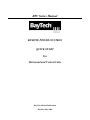
RPC Series Manual
REMOTE POWER CONTROL
QUICK START
For
Horizontal and Vertical Units
BayTech Manual Publication
Revision May 2008
Copyright 2007 by Bay Technical Associates, Inc.
BayTech, is a registered trademarks of Bay Technical Associates, Inc.
Windows 2000®, Windows XP® are products and registered trademark of Microsoft
Corporation.
Tera Term is a product and registered trademark of Vector, Inc.
2
For those Administrators who have requested the bare minimum for this type of equipment, follow
these steps exactly. If this is a new unit shipped directly from Baytech, follow the steps. If this is a
previously own unit, perform a factory reset to clear out any users and passwords still in the unit.
Outlet Control:
1. Connect the 9FRJ45PC-4 or 9FRJ45PC-1 adapter to your PC.
2. Connect the supplied rollover flat cable RJ08X007 to the adapter and to the EIA232 serial
port on the Baytech RPC device.
3. Use terminal emulation software to access the unit, (i.e. Microsoft Hyper-terminal). Set the
PC serial port configuration to the following: 9600 bps, 8 data bits, 1stop bit and no
parity. If your device has a B/C switch near the EIA232 port, set it to ‘B’.
4. If you get only a blinking cursor Press ‘Enter’. If still only a blinking cursor, Type 5 semicolons (;), there is a one second delay before the menu is displayed.
5. You should get the Outlet Status menu (Figure 1). This is the outlet controller circuits. If
you get the Network Menu (Figure 7), select option 1, Outlet Control to get to the Outlet
Status menu.
6. Type config and press ‘Enter’. You should see a menu similar to (Figure 4).
7. Select number for the Manage Users option. You should see a menu similar to (Figure 5).
8. IMPORTANT NOTE: the first user added will be the ADMIN user. Type ‘A’ and press
‘Enter’. Type the name of the admin user. The name is case sensitive.
9. Select the user number. You should see the name of the user selected a menu similar to
(Figure 6).
10. Select ‘Add Outlet(s)’ to add a few outlets (i.e. 1,2,4) and press ‘Enter’ or select ‘Add All
Outlet’. A ‘Y’ signifies the outlet has been assigned to the user.
11. Press ‘Enter’ You should see a menu similar to (Figure 5). Repeat steps 7 thru 9 to add other
users.
12. Once you have added the users press ‘Enter’ until you get back to the Outlet Status menu,
(Figure 1). Type ‘Exit’. With (Microsoft Hyper-terminal) pressing ‘Enter’ will reconnect to
the unit outlet controller and ask for a use name. If this does not happen close the terminal
emulator session and open it again.
13. Type the name of a user to log in. You should see a menu similar to (Figure 1). The user will
see only the outlets assigned to them.
14. At the prompt type ‘password’ and press ‘Enter’. You should see prompts similar to (Figure
3).
15. Enter the password for the user. Repeat steps 12 thru 14 to add or change the password of
the user.
At this point you have enough Outlet Control Configurations to operate this Baytech Device.
Continue to the Ethernet Controller Configuration.
Ethernet Controller Configuration:
Before continuing your System Administrator needs to tell you to use DHCP or give you an IP
Address, Subnet Address, and Gateway Address.
1. If this Baytech device has an Ethernet port, at the prompt of any menu type five Attention
Characters (factory default is the semi-colon, {;}). The Attention Character will not echo on
the screen. You should see a menu similar to (Figure 7).
2. Select ‘C’ for the configuration menu. You should see a menu similar to (Figure 8).
3. Select the number for ‘Login Setup’ option. You should see a menu similar to (Figure 9).
4. Select the number for ‘Manage Users’ option. You should see a menu similar to (Figure 10).
3
5. NOTE: The ‘root’ user can not be deleted.
6. Select ‘A’ to add user. Type the name and password at the prompts.
7. Press ‘Enter’ until get to the ‘Login Setup Menu’ (Figure 9).
8. Select option ‘Access Control’ to enable or disable the Tenet and Serial Login Prompt.
9. Press ‘Enter’ until you get the Configuration menu (Figure 8).
10. Select ‘Network Port Configuration’ option. You should see a menu similar to (Figure 11).
11. If your System Administrator requires you to use DHCP, then select ‘DHCP
Enable/Disable’ and type ‘Y’ to enable DHCP. If you wish to assign a static IP address to
this unit, Disable the DHCP and go to step 15.
12. Press ‘Enter’ until you are asked to ‘Accept Changes’. Type ‘Y’ to accept changes or ‘N’ to
decline changes.
13. After Accepting or Declining Changes you should get the Network Access Menu (Figure 7).
14. Select ‘Unit reset’ to update the external connections. Once the reset is completed (1 minute)
connect the Baytech device to your network using an Ethernet cable.
15. If you disabled the DHCP in step 11, you should see a menu similar to (Figure 11).
16. Select the ‘IP Address’ option and type the assigned IP address and press ‘Enter’.
17. Select the ‘Subnet Mask’ option and type the assigned subnet mask address and press
‘Enter’.
18. Select the ‘Gateway Address’ option and type the assigned Gateway address and press
‘Enter’.
19. Press ‘Enter’ until you are asked to ‘Accept Changes’. Type ‘Y’ to accept changes.
20. Select ‘Unit reset’ to update the external connections. Once the reset is completed (1 minute)
connect the Baytech device to your network using an Ethernet cable.
At this point you have enough basic configurations needed to operate this Baytech unit.
4
QUICK START: Combined RPC Series
by Bay Technical Associates
•
•
•
•
Connect the 9FRJ45PC-4 adapter to the user’s computer
Connect the RPC EIA-232 port to the adapter via the RJ08X007 rolled flat ribbon cable.
NOTE: The RJ08X007 is NOT an RJ45 network cable.
Use terminal emulation software to access the unit, 9600 bps, 8 data bits, 1stop bit and no
parity, B/C switch set to ‘B’.
NOTE: At any time during the session you need to go to the Network Access menu, use the
Attention Character = semi-colon (;). Press the attention character key 5 consecutive times to
get back to the Network menu.
NOTE: Password feature is case sensitive. (Default is user/password is root/baytech)
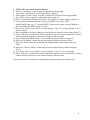
Interior Architecture
Horizontal Units
Power Controller: The power controller
connects to the relay board to control the
outlets. EIA-232 Port maybe on either
controller.
Vertical Units
Power Controller: The power controller
connects to the relay board to control the
outlets. EIA-232 located on Controller.
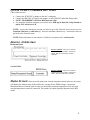
Status Screen: Once the serial connection is made using the terminal software, the screen
will display the inherent state of the outlets, the Average Power, RMS voltage, Current and
Maximum Detected Current both in Amps, circuit breaker, Internal temperature of the unit, and
external temperature sensors if connected. The number of outlets displayed depends on the RPC
model.
5
Figure 1
Unit ID: RPC3ADE-20
------------------------------------------------------------------------------|
Outlet
| True RMS | Peak RMS | True RMS
|
Average | Volt- |
|
Group
| Current | Current |
Voltage
|
Power
| Amps
|
------------------------------------------------------------------------------| Outlet 1-8
| 0.2 Amps | 0.2 Amps | 120.7 Volts |
23 Watts |
23 VA |
------------------------------------------------------------------------------Internal Temperature: 73.4 F Ext: 68.2 F
Switch 1: Open 2: Open
1)...Outlet
2)...Outlet
3)...Outlet
4)...Outlet
5)...Outlet
6)...Outlet
7)...Outlet
8)...Outlet
1
2
3
4
5
6
7
8
:
:
:
:
:
:
:
:
On
On
On
On
On
On
On
On
Type Help for a list of commands
RPC>
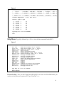
Help Menu: Type Help followed by a <CR> to view the line commands for the RPC’s.
Figure 2
RPC>help
On n <cr>
Off n <cr>
Reboot n <cr>
Status <cr>
Config <cr>
Lock n <cr>
Unlock n <cr>
Current <cr>
Voltage <cr>
Power <cr>
Clear <cr>
Temp <cr>
Logout <cr>
Logoff <cr>
Exit <cr>
Password <cr>
Whoami <cr>
Unitid <cr>
--Turn on an Outlet, n=0,1...20,all
--Turn off an Outlet, n=0,1...20,all
--Reboot an Outlet, n=0,1...20,all
--RPC-28 Status
--Enter configuration mode
--Locks Outlet(s) state, n=0,1...20,all
--Unlock Outlet(s) state, n=0,1...20,all
--Display True RMS Current
--Display True RMS Voltage
--Display Average Power
--Reset the maximum detected current
--Read current temperature
--Logoff
--Logoff
--Logoff
--Changes the current user password
--Displays the current user name
--Displays the unit ID
Type Help for a list of commands
Enter Request:
Password setting: Once you have logged out and log back in as a user or as the administrator, you
can then set the password to gain access. Type “Password”<cr>
6
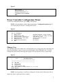
Figure 3
RPC>password
Enter new Password: *****
Re-Enter new Password: *****
Type Help for a list of commands
RPC>
Power Controller Configuration Menu:
To select the configuration menu, type ‘config’ at the prompt.
NOTE: If the unit display with the following message, “Configuration mode in use” A
user in the other port is in the “Configuration” menu.
Figure 4
RPC>config
Unit ID: RPC3ADE-20
1)...Manage Users
2)...Change Outlet Name
3)...Enable/Disable Confirmation
4)...Enable/Disable Status Menu
5)...Change Unit ID
6)...Change Alarm Threshold
X)...Exit
Add/Delete/Rename, assign outlets
Select an outlet to change its name
Confirmation (Y/N)
Opening status of outlets
As written
As written
Manage User
The User Menu allows the admin user to add and delete users, change passwords, and change the
outlet list that displays a user’s access to prescribed outlets. Select “Manage Users,” from the
configuration menu and the following menu appears if the unit has been reset or initial setup:
Figure 5
------------------------------------------|
User
|
Assigned Outlets
|
|
| 1| 2| 3| 4| 5| 6| 7| 8|
------------------------------------------------------------------------------------A)...Add User
D)...Delete User
R)...Rename User
G)...Change Outlet Group
Enter user number to assign Outlets, A, D, G or R.
Enter Request:
NOTE: User in position (1) will be the ‘admin user’ for the outlets. Older units will not
display the ‘delete’ option until a user is added.
7
Add a User:
Select A), “Add user,” from the User Management Menu. Enter the name of the user to be added,
followed by <cr>. NOTE: User name is case sensitive.
Assigned Outlets
Select a user number from the User Management Menu, the RPC unit will display the Assign Outlet
Menu:
Figure 6
------------------------------------------|
User
|
Assigned Outlets
|
|
| 1| 2| 3| 4| 5| 6| 7| 8|
------------------------------------------1) engineer
| N| N| N| N| N| N| N| N|
------------------------------------------1)...Add Outlet(s)
Add individual Outlets (X, X, X, X)
2)...Remove Outlet(s)
Remove individual Outlets
3)...Add All Outlets
Add all outlets to above user
4)...Remove All Outlets
Remove all Outlets from the above user
Enter Request:
NOTE: If an outlet user’s list is changed while the user is logged in, their outlet list changes
dynamically. If enabled, an updated outlet status report will be issued. ‘Y’ means the outlet
is assigned to the user. ‘N’ means the outlet is NOT assigned to the user.
Change Outlet Name: Allows the administrator to change the name of the outlets.
Enable/Disable Confirmation: Enables/Disables the confirmation of choices. Example, “Turn off
all outlets [Y/N]?”
Enable/Disable Status Menu: Enables/Disables the status screen. Example, the screen with the
Amperage and Voltage readings is shown when you first log on to the unit.
Change Unit ID: Allows the user to change the name of the unit. The defaulted is something
similar to RPC3ADE-20. Allows the user to personalize or customize name or location, up to 31
alphanumeric characters.
Change Alarm Threshold: The Alarm Threshold is the value set that sounds the amperage alarm
when it reaches or exceeds the amperage value indicated.
Universal Ethernet Controller Configuration:
Newer models of RPC units (with the environmental ports) show a different access menu that the
RPC-NC models
Access Menu: The Access Menu screen, allows for Outlet Operations, Network Configuration,
or Disconnection. To access the Network Configuration Screen, type five Attention Characters.
8
NOTE: For initial network access, the IP address, subnet mask, and gateway must be
configured from the serial port. Default setting is 0.0.0.0.
Figure 7
Module: 1
Attention Character: ;
Outlet Control..................1
Status..........................S
Configure.......................C
Unit Reset......................RU
Unit Status
Unit Configuration menu
Terminates external connections, does not
effect the outlets.
Logout..........................T
Enter Request :s
Figure 8
Copyright(C) Bay Technical Associates 2003
URPC Ethernet Host Module
Revision F 1.07.05
Module 1
Hardware 1.01
Serial number 3800024
Status..........................1
Serial Port Configuration.......2
Serial Port Device Name.........3
Attention Character.............4
Disconnect Timeguard............5
Connect Port ID Echo............6
Login Setup.....................7
Network Port Configuration......8
Module Name.....................9
SNMP Configuration.............10
RPC Management.................11
Web Server Configuration.......12
Radius Configuration...........13
colilo version 1.05.01
Status of all network options
Setup the Serial port EIA232
Change the EIA232 port name
Type 5 times to access Network Main menu.
Data received within the delay period,
is data, not attention character; thereby
preventing unwanted port disconnection
Echo port name or module# & port#
Login Menu Serial/Telnet/Radius/TACACS
access control, manage users
Network Port IP Address
Change name of module
Trap address, Read/Write community names,
Enable/Disable SNMP
Set up Voltage/Current/Sensor threshold
Enable/Disable Web, login, secure.
Enable login, IP Address, Backup server,
Login timeout for Authentication server
Exit.........................X,CR
Enter Request :
9
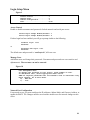
Login Setup Menu
Figure 9
Access Control..................1
Manage Users....................2
Radius Configuration............3
Exit............................X,CR
Access Control
Enable or disable usernames and passwords for both network and serial port access.
Telnet Login Prompt Enable/Disable..1
Serial Login Prompt Enable/Disable..2
If either login has been enabled you will get a prompt similar to the following:
Coldfire login: root
Password:
or
Universal RPC login: root
Password:
The default user and password is “root/baytech”, all lower case.
Manage Users
Add/delete users and change their passwords. Usernames and passwords are case sensitive and
alphanumeric. The root user can not be removed.
Figure 10
User Management Menu
To change user password or port access, enter number of user.
To add/delete user, select appropriate menu choice.
SNMP V3 requires passwords that are between 8 and 31 characters long
Enter request, CR to exit menus.
A)...Add user
1)...root
Network Port Configuration
For network access, you must configure the IP addresses, Subnet Mask, and Gateway Address, or
enable the DHCP. The Changes must be saved and the module reset for network changes to take
effect.
10
Figure 11
Network setup :
Ethernet Address................
IP Address......................
Subnet Mask.....................
Default Gateway.................
00:C0:48:00:01:FD
70.150.140.89
255.255.255.224
70.150.140.65
Connection Inactivity Timeout (mins): Disabled
Carriage Return Translation: Enabled
Break Length (msecs): 350
DHCP is Disabled
Telnet is Enabled
SSH is Enabled
SSH host keys are set to factory default
IP Address........................1
Subnet Mask.......................2
Gateway Address...................3
Inactivity Timeout................4
Carriage Return Translation.......5
Break Length......................6
DHCP Enable/Disable...............7
Telnet Enable/Disable.............8
SSH Enable/Disable................9
SSH Host Key Generation...........10
IP Filter Configuration...........11
SNMP Configuration................12
Web Server Configuration..........13
Exit..............................X,CR
Enter Request :
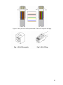
CABLING
RJ-45 Cable
IMPORTANT: The BayTech unit has an RJ45 port, which uses an 8-pin rollover cable to
connect to the local EIA232 device, such as a computer terminal or external modem. For
those serial computers that do not have an RJ45 connection, an adapter is provided to
connect from a DE-9 connector to a RJ-45 connector, (see cable and adapter diagram). An
adapter to convert from a DB25 connector to an RJ45 connecter is also available from
BayTech, upon request. The 8-pin rollover modular cable is configured to operate with
either adapter.
CAUTION: All power should be removed from the BayTech unit prior to removing or
installing cables and /or adapters.
11
RPC RJ-45 pin Signals
Pin EIA 232
Signal
Signal
Direction
1
DTR
Out
2
GND
3
RTS
Out
4
TX
Out
5
RX
In
6
N/C
In
7
GND
8
DCD
In
Description
+10V when activated by DCD. Toggles on logout for modem disconnect.
Signal Ground
+10 V when power is applied. Not used as a handshake line.
Transmit (Data Out)
Receive (Data In)
No Connection.
Signal Ground
DCD into the RPC.
Adapter signals
Listed are the pin specifications for the BayTech cable and adapters and the terminal COM ports:
Signal
DTR
GND
RTS
TXD
RXD
DSR
GND
CTS
DTR
DCD
RI
RS-232
Port (DS)
1
2
3
4
5
6
7
8
RS-232
Port (RPC)
1
2
3
4
5
N/C
7
8
9
COM Port
DE-9 Pin
4
7
3
2
6
5
8
4
1
COM Port
DB-25 Pin
20
1
5
2
3
6
7
4
8
22
Signal
DSR
GND
CTS
RXD
TXD
DTR
GND
RTS
DCD
DTR
Adapters:
9FRJ45PC (With Cisco Interface) 9FRJ45PC-1 (Without Cisco Interface)
12
Figures 1 and 2 provide visual representation of an RJ-45 receptacle and plug.
13