1
GENERAL
INTRODUCTION
Caution should be exercised during these operations.
The excel HE range of boilers are wall mounted, full sequence,
automatic spark ignition, low water content, fanned flue, high
efficiency, condensing, combination gas boilers.
Operatives should be knowledgeable in handling techniques
when performing these tasks and the following precautions
should be considered:
Note. Due to the high efficiency of the boiler a plume of water
vapour will form at the terminal during operation.
•
•
•
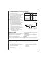
Central heating (CH) and instantaneous domestic hot water
(DHW) outputs are fully modulating with a maximum of :
C24
23.4kW (80,000 Btu/h)
C28
28.0kW (95,500 Btu/h)
C32
32.0kW (109,000 Btu/h)
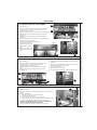
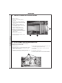
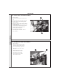
Grip the boiler as described in Frame 28.
Be physically capable.
Use PPE as appropriate, e.g. gloves, safety footwear.
During all manoeuvres and handling actions, every attempt
should be made to ensure the following unless unavoidable
and/or the weight is light.
Variable CH and DHW temperature controls are fitted on the
user control.
•
•
•
•
•
•
•
The boiler casing is of white painted mild steel with a plastic
drop down controls access door.
OPERATION
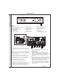
The boiler temperature controls are located behind the controls
access door.
With no demand for CH, the boiler fires only when DHW is
drawn off.
The main heat exchanger is made of copper, the high efficiency
recuperator is made of stainless steel and the DHW plate heat
exchanger is made of stainless steel.
When there is a demand for CH, the heating system is
supplied at the selected temperature of between 38oC and
82oC, until DHW is drawn off. The full output from the boiler is
then directed via the diverter valve to the plate heat exchanger to
supply a nominal DHW draw-off of :
The boilers are supplied fully assembled with DHW plate heat
exchanger, diverter valve, circulating pump, pressure gauge,
safety valve and CH expansion vessel.
The boiler is suitable for connection to fully pumped, sealed
water systems ONLY. Adequate arrangements for completely
draining the system by provision of drain cocks MUST be
provided in the installation pipework.
A system bypass is not required when TRV’s are fitted to ALL
radiators (see Frame 5). The boiler incorporates an automatic
bypass.
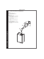
Pipework from the boiler is routed downwards as standard, but
may be routed upwards behind the boiler using the stand-off
frame (supplied in a separate kit).
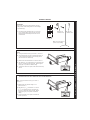
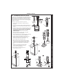
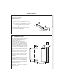
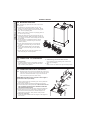
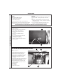
SAFE HANDLING
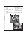
This boiler may require 2 operatives to move it to its installation
site, remove it from its packaging and during movement into its
installation location. Manoeuvring the boiler may include the
use of a sack truck and involve lifting, pushing and pulling.
1
Keep back straight.
Avoid twisting at the waist.
Avoid upper body/top heavy bending.
Always grip with the palm of the hand.
Use designated hand holds.
Keep load as close to the body as possible.
Always use assistance if required.
C24 9.6 l/min (2.1 GPM) at 35oC rise.
C28 11.5 l/min (2.6 GPM) at 35oC rise.
C32 13.1 l/min (2.9 GPM) at 35oC rise.
Note. Quoted flow rates and temperature rises are those
theoretically achievable. Flow rates measured during
commissioning may differ (due, for example, to resistance of
domestic hot water pipe lengths and fittings or available
dynamic gas pressures).
Due to system variations and seasonal temperature
fluctuations DHW flow rates/temperature rise will vary, requiring
adjustment at the draw off tap.
At low DHW draw-off rate the maximum temperature is limited
to 65o C by the modulating gas control.
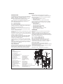
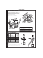
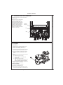
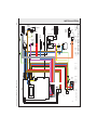
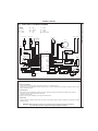
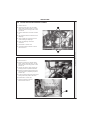
Refer also to Frame 1 - 'Boiler Water Circuit Diagram'.
34
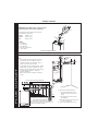
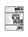
BOILER WATER CIRCUIT DIAGRAM
25
24
37
23
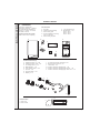
LEGEND
1. DHW plate heat exchanger
2. DHW flow switch
3. DHW outlet pipe
4. Domestic cold water inlet cock
5. 3 - way diverter valve
6. Main circuit drainage cock
7. CH flow cock
8. By-pass valve
9. CH return cock
10. 3 Bar pressure relief valve
11. Gas cock
12. Expansion vessel
13. Gas valve inlet pressure tap
14. Modulating gas valve
15. Burner pressure tap
16. Flame detection electrode
17. Ignition electrodes
18. Burner
19. Combustion chamber
20. Primary heat exchanger
21. Fan
6
27
22
35
36
21
22.
23.
24.
25.
26.
27.
28.
29.
30.
31.
32.
33.
34.
35.
36.
37.
20
Air pressure switch
19
Venturi device
Flue outlet pipe
17
Air intake pipe
16
Automatic air vent
18
Overheat thermostat
Pump
15
Pump vent plug
14
CH thermistor
CH flow switch
13
DHW thermistor
CH temperature pressure gauge
Recuperator
Sensor dry fire/condensate blockage thermistor
Condensate pipe
Collector flue condensate
12
1
30
10
33
32
26
2
28
29
31
5
11
ix7410
9
8
7
6
4
3
excel HE - Installation and Servicing