1
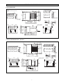
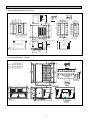
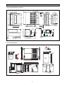
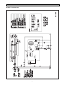
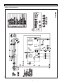
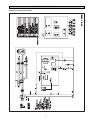
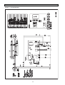
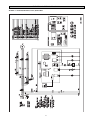
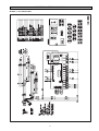
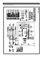
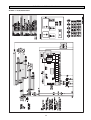
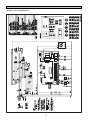
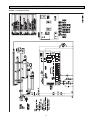
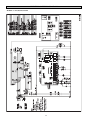
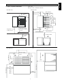
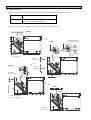
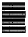
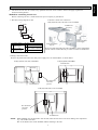
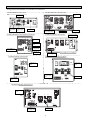
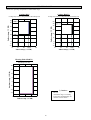
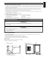
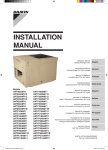
INSTALLATION
MANUAL
Installation Manual
Rooftop Package Units
Installationshandbuch
Kompaktanlage Für Dachmontage
Deutsch
Manuel D’installation
Conditionneurs D’air En Toiture
Français
Installatiehandboek
Compactsysteem Voor Dakmontage
Models
UAT180AMY1
UAT240AMY1
UAT280AMY1
UAT320AMY1
UAT450AMY1
UAT560AMY1
UAT700AMY1
UAT850AMY1
UATC10AMY1
UATC12AMY1
UATP180AMY1
UATP240AMY1
UATP280AMY1
UATP320AMY1
UATP450AMY1
UATP560AMY1
UATP700AMY1
UATP850AMY1
UATPC10AMY1
UATPC12AMY1
UATY180AMY1
UATY240AMY1
UATY280AMY1
UATY320AMY1
UATY450AMY1
UATY560AMY1
UATY700AMY1
UATY850AMY1
UATYC10AMY1
UATYC12AMY1
UATYP180AMY1
UATYP240AMY1
UATYP280AMY1
UATYP320AMY1
UATYP450AMY1
UATYP560AMY1
UATYP700AMY1
UATYP850AMY1
UATYPC10AMY1
UATYPC12AMY1
English
Manual De Instalación
Unidades Del Conjunto Del Tejado
Manuale Di Installazione
Unità A Pacchetto Per Installazione Sul Tetto
Εγχειρίδιο Εγκατάστασης
Μονάδες Συσκευασίας Της Κορυφής Της Οροφής
Manual De Instalação
Unidades De Conjuntos De Telhado
Руководство По Установке
Компактные Установки Для Кондиционирования
Воздуха, Монтируемые На Крыше Здания
Kurulum kılavuzu
Çatı Tipi Ambalaj Üniteleri
Nederlands
Español
Italiano
Ελληνικά
Portugues
Русский
Türkçe
OUTLINE AND DIMENSIONS
10
UAT(Y)(P)180AMY1
25
46
150 150 150 150
668
49
10
170 170 36
1142
1100
1192
Return air duct flange
36
1100
668
25
A Detail
B Detail
Hanger (4 places)
668
232
1000
200
Supply
air
Return
air
Control box
Condenser
Air inlet
Drain R 1
71
135
Return air
192 230
Supply air
412
31
360
25
15
(1342)
1000
25
25
540
16- ø3 Holes
15
(1342)
B
265
25
46
4-15X25 Mtg. holes
265
200
34
232
16- ø3 Holes
51
Supply air duct flange
34
200
10
49
10
125 125 125 125 20
1020
15 100100 15
20
A
51
(unit ; mm)
Except : Drain size. (unit ; inch)
437
Wiring hole
1530
50
1342
1300
1392
1020
Return air
173
Supply
air
Return
air
Control box
LP1 HP1
71
107
1000
Supply air
50
437
Drain R1
Wiring hole
Check Joint
1530
i
B Detail
25
20- ø3
25
B
265
Hanger (4 places)
192 230 31
173
412
1020
135
107
1000
25
15
(1342)
4-15X25 Mtg. holes
265
25
46
51
20- ø3
15
(1342)
1020
1300
173
Return air duct flange
36 170 170 36
60 150 150 150 150 150 150 60
49
1020
10
10
Supply air duct flange
49
10
15100100 15
60 150 150 150 150 150 150 60
1020
10
107
51
A
25
46
UAT(Y)(P)240,280,320AMY1 - Side flow
25
A Detail
Condenser
Air inlet
OUTLINE AND DIMENSIONS
UAT(Y)(P)240,280,320AMY1 - Down flow
25
46
4-15X25 Mtg. holes
B
265
1000
368
15
(1342)
10
96
10 261
812
10
96
Supply air duct flange
Return air duct flange
1300
51
265
10
10
49 160 160
87
View C (Bottom view)
281
41 100100 40
832
160 160 160 160
49
1058
49 160 160 160 160 160 160
25
46
51
832
Supply air
A
25
Detail B
372
46 140 140 46
Detail A
226
1058
Return air
242
155
45
281
1342
1300
1392
637
372
1038
10
320 160 160 49
25
Condenser
Air inlet
15
(1342)
25
25
10
10
16- ø3 Holes
19- ø3 Holes
1000
Hanger (4 places)
Drain R 1
Control
box
Condenser
Air inlet
9
71
(4)RT80,
100A only
9
Wiring hole
Return air
437
Supply air
1530
C
UAT(Y)(P)450,560AMY1 - Side flow
15
(2032)
46
25
51
123
25
Detail A
10
C.O.
H.P
B
1200
1330
25
A
A
1670
1800
49
1990
2032
2082
4-15X25 Mtg. holes
B
B
235
123
428
1744
Return air
C.O. only
123
Return air
Detail B
Hanger (4 places)
Supply
air
1200
124 428 169
77
Supply air
25
235
123
1744
46
25
51
123
25
51
123
15
(2032)
Supply air & Return air
Duct flange
Control box
Condenser
Air inlet
Return
air
Condenser
Air inlet
Condenser
Air inlet
HP1
LP1
483
50
HP2
LP2
Drain R 1
Check Joint
Wiring hole
A
ii
428
1744
34 120120 120 34
1744
1990
72 200 200200200200200 200200 72
10
26- ø3 Holes
OUTLINE AND DIMENSIONS
368 10
Hanger
10
Detail B
(4 places)
1200
Control box
C.O.
only
RT-A
RT-AR
Return air
483
Supply air
Drain R 1
A
8
B
1200
1330
8
77
A
1670
1800
Condenser
Air inlet
Condenser
Air iinlet
Condenser
Air inlet
Wiring hole
C
UAT(Y)(P)700,850AMY1
383
27.5 15
144
25
144
22.5
Return
air
383
A
10
25
144
80
23
2768
2200
165
566
758
100
144
Supply air
duct Flange
80
2850
2720
50
Condenser
air inlet
1302
1735
Return air
duct flange
Condenser
Air inlet
Control
box
10
Wiring hole
Drain R1
iii
28- 3
10
Condenser
Air inlet
320
510
640
Supply air
Return
air
80 150 150 150 150 80
758
1302
51 150 150 150 150 150 150 150 150 51
640
80 120 120 120 12080
20- 3
1146
43 120 120 120 120 43
566
2200
1912
10
80
80
Supply
air
Detail A
1412
Supply air duct flange
10
24- ø3 Holes
10
86
1762
1432
180 180 180 180 180 180 180
86
10
10
359
59.5 120120 59.5
25
25
372
46 140140 46
10
1990
2032
2082
15
(2032)
104
51
235
View C (Bottom view)
B
235
4-15X25 Mtg. holes
B
46
25
1432
1990
Detail A
294
1782
Return air
Supply air
264
104
25
91
15
359
Return air duct flange
25
717
372
(2032)
1782
200 200 200 200 200 200 200 200 91
A
51
79
46
25
UAT(Y)(P)450,560AMY1- Down flow
339 10
22- ø3 Holes
OUTLINE AND DIMENSIONS
3148
UAT(Y)(P)C10,C12AMY1
iv
ELECTRICAL WIRING DIAGRAM
MODEL:UAT(P)180AMY1
v
ELECTRICAL WIRING DIAGRAM
MODEL:UATY(P)180AMY1
vi
ELECTRICAL WIRING DIAGRAM
MODEL:UAT(P)240,280,320AMY1
vii
ELECTRICAL WIRING DIAGRAM
MODEL: UATY240,280AMY1
viii
ELECTRICAL WIRING DIAGRAM
MODEL: UATYP240,280AMY1,UATY(P)320AMY1
ix
ELECTRICAL WIRING DIAGRAM
MODEL: UAT(P)450,560AMY1
x
ELECTRICAL WIRING DIAGRAM
MODEL: UATY450,560AMY1
xi
ELECTRICAL WIRING DIAGRAM
MODEL: UATYP450,560AMY1
xii
ELECTRICAL WIRING DIAGRAM
MODEL: UAT(P)700,850AMY1
xiii
ELECTRICAL WIRING DIAGRAM
MODEL: UATY(P)700,850AMY1
xiv
ELECTRICAL WIRING DIAGRAM
MODEL: UAT(P)C10,12AMY1
xv
ELECTRICAL WIRING DIAGRAM
MODEL: UATY(P)C10,12AMY1
xvi
1. Outline And Dimensions
2. Electrical Wiring Diagram
3. Installation of the Unit
4. Physical Data
5. Electrical Data
page i-iv
page v-xvi
page 1~4
page 5
page 6
6. Wire connection
7. Operating Range
8. Refrigerant
9. Service and Maintenancen
10. Trouble Shooting
page 7~9
page 10
page 11
page 11
page 12
SAFETY PRECAUTIONS
Before installing the air conditioner unit, please read the following safety precautions carefully.
! Caution
Please take note on the following important points when installing.
• Do not install the unit where leakage of flammable gas may occur.
If gas leaks and accumulates around the unit, it may cause fire ignition.
• Ensure that the drainage piping is connected properly.
• Do not overcharge the unit.
This unit is factory pre-charged. Overcharge will cause over-current or damage to the compressor.
• Ensure that the unit service panel is closed after service or installation.
Unsecured panel will cause unit to operate noisily.
INSTALLATION OF THE UNIT
1.1 Location For Installation
• Install the unit in such way that air distributed by the unit cannot be drawn in again (as in the case of short circuit
of discharge air). Allow sufficient space for maintenance around the unit.
• When two or more units are installed in a location, they must be positioned such that one unit will not be taking
the discharge air from another unit.
• Ensure that there is no obstruction of air flow into or out of the unit. Remove obstacles which block air intake or
•
•
•
•
•
•
•
•
•
•
air discharge.
The location must be well ventilated, so that the unit can draw and distribute plenty of air
A place capable of bearing the weight of the outdoor unit and isolating noise and vibration.
A place protected from direct sunlight. Otherwise use an awning for protection, if necessary.
A place where smooth drainage of rain water and water formed by defrosting is acceptable.
A place where the unit will not be buried in snow.
A place where air outlet port is not exposed to strong wind.
A place where the air discharge and operating sound level will not annoy the neighbours.
The location must not be susceptible to dust or oil mist.
The location where it is not accessible by general public.
Keep the unit, power cable and transmission wiring, at least 1 m away from TVs and radios, to prevent distorted
pictures and static. (Depending on the type and the source of the electrical waves, static may be heard even when
more than 1 m away)
1
English
INDEX
INSTALLATION OF THE UNIT
1.2 Unit Support
Roof curb
Unit
1. The figure shows the use of the roof curb
for mounting these units.
Seal with tar
Roof deck
2. The curb should be sealed and fixed to the
roof by weather stripping. A suggested
means of sealing the unit and roof curb as
shown in the left.
4 - ø15
Roof mounting holes
6 - ø15
Unit mounting holes
Roof curb
1.3 Duct Construction
•
•
•
•
•
•
These unit are equiped with supply and return air openings. Duct connection to the unit should be made with
duct flanges and secured directly to the air openings with flexible duct connectors to avoid normal noise
transmission.
To prevent air leakage, all duct seams should be sealed.
Ducts in the spaces that not air-conditioned, must be insulated.
Ducts exposed to the outside must be weather proofed.
Ducts that entering building through the roof, the entering should be sealed with weather stripping to prevent
the rain, sand, dust etc. from entering the bulding.
Correct size of filter must be install at the return air duct.
1.4 Unit Lifting
UAT 180~560
Hanger brackets at 4 corner of the unit are
used for unit lifting purpose.
UAT 700,850
Hanger Bracket
Chain
A
The angle A of the chain should be at
least 45°, and insulation should be added
at 4 corner of the chain to prevent the damage
of the panel when lifting.
1.5 Drain piping
•
Spreader Bar
Lifting Beam
Chain
The drain piping should have a drain trap.
B
•
C
•
A 1 FPT condensate drain fitting is provided. The drain pipe
can be led out at the front side.
The drain pipe must be provided with a trap on the outside
of the unit and also installed at an incline for proper drainage,
as shown in the right.
To prevent condensate formation and leakage, provide the
drain pipe with insulation to safeguard against sweating.
Upon completion of the piping work, check that there is no
leakage and that the water drains off properly.
A
•
A ≥ 70mm
B ≥ 2C
C ≥ 2XE. S. P
Drain trap
Drain piping
The drain pipe
should extend
below this level.
Lifting Holes for shackle
(4 corners)
Note: ESP = External Static Pressure
Drain trap for condensate
UAT C10,C12
2
1.6 Space required around units
English
INSTALLATION OF THE UNIT
(unit ; mm)
All space value ; minimum clearance
UAT 450, 560
300
Condenser
inlet
(min clearance)
500
Evaporator coil,
air filter service
1000
UAT 180~320
300
Condenser
inlet
300
Electrical
control circuit
& compressor
service
700
Evaporator coil,
air filter service
Condenser
inlet
1000
700
Evaporator coil,
air filter service
1000
300
Electrical control
circuit & compressor
service
(min clearance)
1500
1500
(min clearance)
Condenser
outlet
Condenser outlet
Condenser
inlet
1000
1500
Electrical control
circuit & compressor
service
Condenser
inlet
(min clearance)
1000
UAT 700~C12
3000
(min clearance)
1000
Evaporator coil,
motor service
(min clearance)
2000
1000
3
Condenser outlet
INSTALLATION OF THE UNIT
1.7 Unit conversion
Please check for accessory parts as below. (Packed in the unit, and available for convertible unit only)
1. Side inlet cover
1 piece
2. Casing leg
2 pieces UAT(Y)(P)240, 280, 320AMY1
4 pieces UAT (Y)(P)450, 560AMY1
In the case of converting to down flow unit, change according to the following steps.
STEP 1
Remove
top panel
2. Additional casing
leg (Accessory parts)
STEP 2
Remove supply
air cover
Remove
service panel
Remove
Remove
duct flange
STEP 3
Remove
duct flange
Re-install
supply air cover
Remove
low cover
Re-install
fan assy
STEP 4
Re-install
top panel
1. Additional side inlet
cover (Accessory parts)
Re-install
service panel
4
EXTERNAL STATIC PRESSURE
CONDENSER AIR FLOW
CONTROL
CONTROL WIRE LENGTH (STANDARD / MAX) : SIZE
COMPRESSOR (TYPE / QUANTITY)
AIR FILTER (TYPE / QUANTITY)
AIR FILTER DIMENSION (LENGTH x WIDTH x THICKNESS)
MODEL
REFRIGERANT
REFRIGERANT CHARGE
EVAPORATOR AIR FLOW
EXTERNAL STATIC PRESSURE
CONDENSER AIR FLOW
CONTROL
CONTROL WIRE LENGTH (STANDARD / MAX) : SIZE
COMPRESSOR (TYPE / QUANTITY)
AIR FILTER (TYPE / QUANTITY)
AIR FILTER DIMENSION (LENGTH x WIDTH x THICKNESS)
kg
CFM
L/S
mmAq
CFM
L/S
UAT180AMY1
UAT240AMY1
5.2
1800
850
4.0
2826
1334
10
5650
2667
SLM CONTROLLER
7 / 15 : 0.14
SCROLL / 1
WASHABLE SARANET / 1
1020 x 615 x 1
4500
2124
m : mm2
mm
kg
CFM
L/S
mmAq
CFM
L/S
UAT280AMY1
R22
5.9
3532
1667
820 x 615 x 1
UAT560AMY1
UAT700AMY1
5.9 x 2
6710
3167
20
11300
5333
10.5 x 2
8000
3776
UAT450AMY1
6.2
3600
1699
4.5 x 2
5651
2667
20
11300
5333
SEQUENTIAL CONTROLLER
- / 100 : 0.14
SCROLL / 2
WASHABLE SARANET / 2
840 x 667 x 1
8000
3776
UAT850AMY1
R22
10.4 x 2
9600
4531
UATC10AMY1
UATC12AMY1
16.5 / 19.5
11000
5191
19.5 x 2
12500
5899
30
20000
9439
SEQUENTIAL CONTROLLER
- / 100 : 0.14
SCROLL / 2
m : mm2
mm
UAT320AMY1
840 x 667 x 1
WASHABLE SARANET / 2
1370 x 735 x 1
WASHABLE SARANET / 2 & 4
860 x 505 & 600 x 4
HEAT PUMP (R22)
MODEL
REFRIGERANT
REFRIGERANT CHARGE
EVAPORATOR AIR FLOW
EXTERNAL STATIC PRESSURE
CONDENSER AIR FLOW
CONTROL
CONTROL WIRE LENGTH (STANDARD / MAX) : SIZE
COMPRESSOR (TYPE / QUANTITY)
AIR FILTER (TYPE / QUANTITY)
AIR FILTER DIMENSION (LENGTH x WIDTH x THICKNESS)
MODEL
REFRIGERANT
REFRIGERANT CHARGE
EVAPORATOR AIR FLOW
EXTERNAL STATIC PRESSURE
CONDENSER AIR FLOW
CONTROL
CONTROL WIRE LENGTH (STANDARD / MAX) : SIZE
COMPRESSOR (TYPE / QUANTITY)
AIR FILTER (TYPE / QUANTITY)
AIR FILTER DIMENSION (LENGTH x WIDTH x THICKNESS)
COOLING ONLY (R407C)
MODEL
REFRIGERANT
REFRIGERANT CHARGE
EVAPORATOR AIR FLOW
EXTERNAL STATIC PRESSURE
CONDENSER AIR FLOW
CONTROL
CONTROL WIRE LENGTH (STANDARD / MAX) : SIZE
COMPRESSOR (TYPE / QUANTITY)
AIR FILTER (TYPE / QUANTITY)
AIR FILTER DIMENSION (LENGTH x WIDTH x THICKNESS)
MODEL
REFRIGERANT
REFRIGERANT CHARGE
EVAPORATOR AIR FLOW
EXTERNAL STATIC PRESSURE
CONDENSER AIR FLOW
CONTROL
CONTROL WIRE LENGTH (STANDARD / MAX) : SIZE
COMPRESSOR (TYPE / QUANTITY)
AIR FILTER (TYPE / QUANTITY)
AIR FILTER DIMENSION (LENGTH x WIDTH x THICKNESS)
HEAT PUMP (R407C)
MODEL
REFRIGERANT
REFRIGERANT CHARGE
EVAPORATOR AIR FLOW
EXTERNAL STATIC PRESSURE
CONDENSER AIR FLOW
CONTROL
CONTROL WIRE LENGTH (STANDARD / MAX) : SIZE
COMPRESSOR (TYPE / QUANTITY)
AIR FILTER (TYPE / QUANTITY)
AIR FILTER DIMENSION (LENGTH x WIDTH x THICKNESS)
MODEL
REFRIGERANT
REFRIGERANT CHARGE
EVAPORATOR AIR FLOW
EXTERNAL STATIC PRESSURE
CONDENSER AIR FLOW
CONTROL
CONTROL WIRE LENGTH (STANDARD / MAX) : SIZE
COMPRESSOR (TYPE / QUANTITY)
AIR FILTER (TYPE / QUANTITY)
AIR FILTER DIMENSION (LENGTH x WIDTH x THICKNESS)
kg
CFM
L/S
mmAq
CFM
L/S
UATY180AMY1
UATY240AMY1
4.5
1800
850
4.7
2826
1334
10
5650
2667
SLM CONTROLLER
7 / 15 : 0.14
SCROLL / 1
WASHABLE SARANET / 1
1020 x 615 x 1
4500
2124
m : mm2
mm
kg
CFM
L/S
mmAq
CFM
L/S
820 x 615 x 1
UATY560AMY1
UATY700AMY1
5.6 x 2
6710
3167
20
11300
5333
10.5 x 2
8000
3776
kg
CFM
L/S
mmAq
CFM
L/S
kg
CFM
L/S
mmAq
CFM
L/S
840 x 667 x 1
kg
CFM
L/S
mmAq
CFM
L/S
UATP180AMY1
UATP240AMY1
4.6
1800
850
4.0
2826
1334
kg
CFM
L/S
mmAq
CFM
L/S
820 x 615 x 1
UATP560AMY1
UATP700AMY1
4.2 x 2
6710
3167
20
11300
5333
9.6 x 2
8000
3776
UATY850AMY1
R22
9.4 x 2
9600
4531
UATYC10AMY1
UATYC12AMY1
16.0 / 20.5
11000
5191
20.5 x 2
12500
5899
WASHABLE SARANET / 2 & 4
860 x 505 & 600 x 4
UATP280AMY1
R407C
5.9
3532
1667
UATP320AMY1
UATP450AMY1
6.2
3600
1699
4.5 x 2
5651
2667
20
11300
5333
SEQUENTIAL CONTROLLER
- / 100 : 0.14
SCROLL / 2
WASHABLE SARANET / 2
840 x 667 x 1
8000
3776
UATP850AMY1
R407C
10.4 x 2
9300
4389
UATPC10AMY1
UATPC12AMY1
14.5 / 18.0
11000
5191
18.0 x 2
12500
5899
30
20000
9439
SEQUENTIAL CONTROLLER
- / 100 : 0.14
SCROLL / 2
840 x 667 x 1
WASHABLE SARANET / 2
1370 x 735 x 1
UATYP180AMY1
UATYP240AMY1
4.3
1800
850
4.7
2826
1334
WASHABLE SARANET / 2 & 4
860 x 505 & 600 x 4
UATYP280AMY1
R407C
5.6
3532
1667
10
5650
2667
SLM CONTROLLER
7 / 15 : 0.14
SCROLL / 1
WASHABLE SARANET / 1
1020 x 615 x 1
4500
2124
820 x 615 x 1
UATYP560AMY1
UATYP700AMY1
5.8 x 2
6710
3167
20
11300
5333
9.4 x 2
8000
3776
UATYP320AMY1
UATYP450AMY1
6.0
3600
1699
5.0 x 2
5651
2667
20
11300
5333
SEQUENTIAL CONTROLLER
- / 100 : 0.14
SCROLL / 2
WASHABLE SARANET / 2
840 x 667 x 1
10000
4719
UATYP850AMY1
R407C
9.6 x 2
9600
4531
UATYPC10AMY1
UATYPC12AMY1
13.5 / 20.5
11000
5191
20.0 x 2
12500
5899
30
20000
9439
SEQUENTIAL CONTROLLER
- / 100 : 0.14
SCROLL / 2
m : mm2
mm
10000
4719
10
5650
2667
SLM CONTROLLER
7 / 15 : 0.14
SCROLL / 1
WASHABLE SARANET / 1
1020 x 615 x 1
4500
2124
m : mm2
mm
4.7 x 2
5651
2667
20
11300
5333
SEQUENTIAL CONTROLLER
- / 100 : 0.14
SCROLL / 2
WASHABLE SARANET / 2
840 x 667 x 1
WASHABLE SARANET / 2
1370 x 735 x 1
m : mm2
mm
UATY450AMY1
6.0
3600
1699
SEQUENTIAL CONTROLLER
- / 100 : 0.14
SCROLL / 2
m : mm2
mm
UATY320AMY1
30
20000
9439
m : mm2
mm
UATY280AMY1
R22
5.6
3532
1667
840 x 667 x 1
WASHABLE SARANET / 2
1370 x 735 x 1
5
WASHABLE SARANET / 2 & 4
860 x 505 & 600 x 4
English
PHYSICAL DATA
COOLING ONLY (R22)
MODEL
REFRIGERANT
REFRIGERANT CHARGE
EVAPORATOR AIR FLOW
ELECTRICAL DATA
COOLING ONLY (R22)
MODEL
POWER SUPPLY
V/ph/Hz
VOLTAGE RANGE
V
MAX CONTINUOUS CURRENT (COMP)
A
FULL LOAD CURRENT (FLA, COMP)
A
LOCKED ROTOR CURRENT (LRA, COMP) A
MODEL
POWER SUPPLY
V/ph/Hz
VOLTAGE RANGE
V
MAX CONTINUOUS CURRENT (COMP)
A
FULL LOAD CURRENT (FLA, COMP)
A
LOCKED ROTOR CURRENT (LRA, COMP) A
HEAT PUMP (R22)
MODEL
POWER SUPPLY
V/ph/Hz
VOLTAGE RANGE
V
MAX CONTINUOUS CURRENT (COMP)
A
FULL LOAD CURRENT (FLA, COMP)
A
LOCKED ROTOR CURRENT (LRA, COMP) A
MODEL
POWER SUPPLY
V/ph/Hz
VOLTAGE RANGE
V
MAX CONTINUOUS CURRENT (COMP)
A
FULL LOAD CURRENT (FLA, COMP)
A
LOCKED ROTOR CURRENT (LRA, COMP) A
COOLING ONLY (R407C)
MODEL
POWER SUPPLY
V/ph/Hz
VOLTAGE RANGE
V
MAX CONTINUOUS CURRENT (COMP)
A
FULL LOAD CURRENT (FLA, COMP)
A
LOCKED ROTOR CURRENT (LRA, COMP) A
MODEL
POWER SUPPLY
V/ph/Hz
VOLTAGE RANGE
V
MAX CONTINUOUS CURRENT (COMP)
A
FULL LOAD CURRENT (FLA, COMP)
A
LOCKED ROTOR CURRENT (LRA, COMP) A
HEAT PUMP (R22)
MODEL
POWER SUPPLY
V/ph/Hz
VOLTAGE RANGE
V
MAX CONTINUOUS CURRENT (COMP)
A
FULL LOAD CURRENT (FLA, COMP)
A
LOCKED ROTOR CURRENT (LRA, COMP) A
MODEL
POWER SUPPLY
V/ph/Hz
VOLTAGE RANGE
V
MAX CONTINUOUS CURRENT (COMP)
A
FULL LOAD CURRENT (FLA, COMP)
A
LOCKED ROTOR CURRENT (LRA, COMP) A
UAT180AMY1
UAT240AMY1
14.0
12.1
74
23.0
15.6
95
UAT560AMY1
UAT700AMY1
26.9 x 2
16.9 x 2
118 x 2
27.5 x 2
22.3 x 2
118 x 2
UATY180AMY1
17.0
15.0
101
UATY560AMY1
31.0 x 2
23.0 x 2
81 x 2
UATP180AMY1
14.0
13.0
74
UATP560AMY1
26.9 x 2
16.9 x 2
118 x 2
UATYP180AMY1
17.0
15.0
101
UATYP560AMY1
26.9 x 2
16.9 x 2
118 x 2
UATY240AMY1
22.0
19.5
84
UATY700AMY1
27.5 x 2
22.3 x 2
118 x 2
UATP240AMY1
23.0
15.9
95
UATP700AMY1
31.0 x 2
22.3 x 2
118 x 2
UATYP240AMY1
23.0
15.9
95
UATYP700AMY1
31.0 x 2
22.3 x 2
118 x 2
6
UAT280AMY1
400 / 3 / 50
380 ~ 415
26.9
16.9
118
UAT320AMY1
UAT450AMY1
27.5
22.3
118
23.0 x 2
15.6 x 2
95 x 2
UAT850AMY1
400 / 3 / 50
380 ~ 415
37.0 x 2
30.0 x 2
198 x 2
UATC10AMY1
UATY280AMY1
400 / 3 / 50
380 ~ 415
31.0
23.0
81
UATY320AMY1
UATY850AMY1
400 / 3 / 50
380 ~ 415
37.0 x 2
30.0 x 2
198 x 2
UATYC10AMY1
UATP280AMY1
400 / 3 / 50
380 ~ 415
26.9
16.9
118
UATP320AMY1
UATP850AMY1
400 / 3 / 50
380 ~ 415
45.0 x 2
30.0 x 2
198 x 2
UATPC10AMY1
UATYP280AMY1
400 / 3 / 50
380 ~ 415
26.9
16.9
118
UATYP320AMY1
UATYP850AMY1
400 / 3 / 50
380 ~ 415
45.0 x 2
32.0 x 2
198 x 2
UATYPC10AMY1
35.0, 50.0
24.0, 30.0
175, 215
27.5
22.3
118
35.0, 50.0
24.0, 30.0
175, 215
31.0
22.3
118
35.0, 50.0
24, 30
175, 215
31.0
22.3
118
35.0, 50.0
24, 30
175, 215
UATC12AMY1
50.0 x 2
30.0 x 2
215 x 2
UATY450AMY1
22.0 x 2
19.5 x 2
84 x 2
UATYC12AMY1
50.0 x 2
30.0 x 2
215 x 2
UATP450AMY1
23.0 x 2
15.6 x 2
95 x 2
UATPC12AMY1
50.0 x 2
30.0 x 2
215 x 2
UATYP450AMY1
23.0 x 2
15.9 x 2
95 x 2
UATYPC12AMY1
50.0 x 2
30.0 x 2
215 x 2
•
All electrical work must be carried out by qualified electrician and accordance with local supply requirement
and associated regulation.
Method for connecting electric wire
Before connecting the wire, consult the electric power company of jurisdiction.
2. Remote control wire connection.
1. The entire wiring diagram of unit.
a
b PE
UAT(Y)(P)450, 560, 700, 850, C10, C12AMY1
LCD Remote
(Top case)
GND
+5
B
A
g
c
Connection at
Mainboard
f
d
GND
+5
B
A
e
a. Power supply
d. Unit
b. Main switch/fuse e. Remote control
(field supply)
f. Connection wiring for
unit & remote controller
c. Power supply
wiring for unit
g. Earth
Connection Wire
(field supply)
Connection behind
Top case
Note: For UAT(Y)(P)180, 240, 280, 320AMY1, wire is attached the
remote control. Connect directly to connector 'CN2' on mainboard.
3. Wiring connection to unit
Remove the panel and connect the units power supply wires to terminal block, as shown below.
UAT(Y)(P)180, 240, 280, 320AMY1
UAT(Y)(P)450, 560AMY1
Terminal block
RT60 only
Terminal block
Recommended
switch box
position
UAT(Y)(P)700, 850, C10, C12AMY1
Recommended
switch box
position
Terminal block
NOTE: While installing the circuit breaker onto the unit, make sure that the screws do not damage the components
(e.g. coil) inside of the unit.
The circuit breaker also can be installed without attaching to the unit.
7
English
WIRE CONNECTION
WIRE CONNECTION
Arrangement of terminal block for controller are shown below.
CONTROL MODULE UAT(Y)(P)180
CONTROL MODULE UATY(P)450,560
UATY(P) only
Connector for
remote control
wires
PCB
52F
52C2
R OOM
52C1
ID 4
PCB
52C
52F1
T1
52F2
4W V 1
47
4W V 2
C
2
47
51F1
O U T F AN 1
X1 X2 X3
O U T F AN 2
F1
6
6
L1
L2
F1
95
98
96
51F1
51C2
51C1
51C
N
L3
X1 X2
TB1
TB2
TB1
L1
L2
L3
N
Connector for Terminal Block
remote control for power supply
wires
wires
UATY(P) only
V
R
S
T
A1
U
V
W
A2
X1
W
6
Connector for remote
control wires
47
52C2
PCB
N
R
S
T
A1
U
V
W
A2
X1 X2
RESET
2
UATY(P) only
UATY(P) only
52C1
N
L
U
T
N
CONTROL MODULE UAT(P)450,560
UATY240,280
only
N
S
N
L IV E
R
52F3
PCB
FZ
52F1
52C
N
Terminal Block for
power supply wires
CONTROL MODULE UAT(Y)240,280, UAT(Y)(P)320
52F2
TB2
N
Connector for
remote control
wires
51C
T
A1
V
W
A2
6
95
98
96
51C1
F1
51C2
TB1
All except for
UATY240,280
52F2
Terminal Block for
power supply wires
R
S
U
S
R
T
N
TB1
2
RESET
95
98
96
47
UATY(P) only
Terminal Block for
power supply wires
CONTROL MODULE UATYP240,280
CONTROL MODULE UAT(Y)(P)700,850
F1
PCB
47
NEUTRAL
DS4
DS3
DS2
DS1
ID4
ID3
ID2
ID1
W
R
S
T
A1
U
V
W
A2
S
T
A1
U
V
W
A2
HP1
HP2
ON/OFF
OUT FAN 4
4WV 1
4WV 3
4WV 2
4WV 4
HEATER 1
HEATER 2
IN FAN
COMP 1
COMP 2
COMP 3
N
T
S
R
PCB
X1
R
COMP 4
52F1
52F2
LIVE
TRANSFORMER
HP3
T
OUT FAN 1
V
OUT FAN 2
S
U
A
B
5V
GND
R
F1
OUT FAN 3
HP4
ROOM
Connector for
remote control
wires
L
52C
52C2
52C1
Connector for
remote control
wires
52F1 &51F1
R
S
T
N
6
RESET
47
2
95
98
96
51F1
51C
TB1
S
T
A1
U
V
W
A2
N
N
R
S
T
A1
U
V
W
A2
52F3
52F2
TB2
N
R
N
Terminal Block
for power supply
wires
51C2
51C1
TB1
Terminal Block
for power supply
wires
X1 X2
L1
L2
L3
UATY(P) only
N
N
1
2
3
4
TB2&3
CONTROL MODULE UAT(Y)(P)C10,C12
F1
Connector for
remote control
wires
47
52F
52C1
52F2
52C2
51F1
PCB
X1
52F3
TB1
51C1
51C2
TB2 & 3
Terminal Block for
power supply wires
UATY(P)
UATY(P) only
only
8
X2
5
Wiring Example and Selection of Circuit Breaker
Values of breaker and wire size are recommended as in table below.
MODEL
UAT(Y)(P)180AMY1
UAT(Y)(P)240AMY1
UAT(Y)(P)280AMY1
UAT(Y)(P)320AMY1
UAT(Y)(P)450AMY1
UAT(Y)(P)560AMY1
UAT(Y)(P)700AMY1
UAT(Y)(P)850AMY1
UAT(Y)(P)C10AMY1
UAT(Y)(P)C12AMY1
POWER CABLE
BREAKER
(mm2)
CAPACITY (A)
8.4
8.4
13.3
13.3
13.3
21.2
33.6
42.4
60.0
60.0
32
32
50
50
50
63
80
100
125
125
380~415V, 50Hz, 3ø
OVER CURRENT
PROTECTION EARTH2 CABLE
(mm over)
SWITCH (A)
32
8.4
32
8.4
50
13.3
50
13.3
50
13.3
63
21.2
80
33.6
100
42.4
125
60.0
125
60.0
Note: A main switch or other means for disconnection, having a contact separation in all poles, must be incorporated in fixed
wiring in accordance with local and national legislation.
• The unit is to be wired directly from an electrical distribution board either by a circuit breaker (preferred) or HRC fuse.
• Fix the power supply wiring to control module. Connect control wiring to control terminal block through the control
box’s hole.
Note: Earth wiring must be connected.
The power supply cord must be equivalent to H05VV-F (60227 IEC 52 or 60227 IEC 53) which is the minimum
requirement, and to be used in protective tube.
Warning:
• Before working on this unit, isolate from the power supply.
• Electrical wiring to this unit and the remote controller shall be installed in accordance with the appropriate
requirements of the local wiring code. e.g. AS3000
9
English
WIRE CONNECTION
OPERATING RANGE
Ensure the operating temperature is in allowable range.
Cooling (R22)
Cooling (R407C)
Cooling Only Unit & Cooling Mode For Heat Pump Unit
Cooling Only Unit & Cooling Mode For Heat Pump Unit
50
46
40
Outdoor temp. (°C DB)
Outdoor temp. (°C DB)
54
50
30
20
10
0
40
30
20
10
0
-5
-5
-10
10
15
20
24 25
-10
10
30
15
20
24 25
Indoor temp. (°C WB)
Indoor temp. (°C WB)
Heating (R22 & R407C)
Heat Pump Unit Only
20
Outdoor temp. (°C WB)
15
10
5
0
-5
-10
! Caution :
-15
10
15
20
25 27
The use of your air conditioner
outside the range of working
temperature and humidity can
result in serious failure.
30
Indoor temp. (°C DB)
10
30
• All units are pre-charged with R407C refrigerant.
• R407C is a zeotropic refrigerant mixture which has zero ozone depletion potential and thus conformed to Montreal Proto
•
•
•
•
•
col regulation. It requires Polyester oil (POE) oil for its compressor lubricant. Its refrigerant capacity and performance are
about the same as the refrigerant R22.
POE oil is used as lubricant for R407C compressor, which is different from the mineral oil used for R22 compressor.
During installation or servicing, exra precaution must be taken not to expose the R407C system too long to moist air.
Residual POE oil in the piping and components can absorb moisture from the air.
Refrigerant R407C is more easily affected by dust or moisture compared with R22, make sure to temporarily cover the
ends of the tubing prior to installation.
No additional charge of compressor oil is permitted.
No other refrigerant other than R407C.
Tools specifically for R407C only (must not be used for R22 or other refrigerant)
i) Manifold gauge and charging hose
iv) Vacuum pump c/w adaptor
ii) Gas leak detector
v) Flare tools
iii) Refrigerant cylinder / charging cylinder
vi) Refrigerant recovery machine
SERVICE AND MAINTENANCE
! Warning
• Disconnect from the main power supply before servicing the air conditioner unit.
• DO NOT pull out the power cord when the power is ON. This may cause serious electrical shocks which may result
in the hazards.
! Caution
• Before turning off the power supply, set the remote controller's ON/OFF switch to the “OFF” position to prevent the
nuisance tripping of the unit.
• If this is not done, the unit's fans will start turning automatically when power resumes, posing a hazard to service
personnel or the user.
SERVICE OF THE FILTER
•
•
•
•
Remove any dust adhering to the filter by using a vacuum cleaner or wash in lukewarm water (below 40°C) with a
neutral cleaning detergent.
Rinse the filter well and dry before placing it back onto the unit.
Do not use gasoline, volatile substances or chemicals to clean the filter.
Clean the filter at least once every 2 weeks. Or more frequently if neccesary.
Filter Position
The filters are mounted in front of the indoor heat exchanger.
* (Air filter : special order or field supply)
UAT(Y)(P)180~560
UAT(Y)(P)700~C12
Filter
Filter
Service panel
Filter cover
removed when servicing
note: both side for unit 450, 560
Filter cover
removed when servicing
11
English
REFRIGERANT & SPECIAL PRECAUTIONS WHEN DEALING WITH R407C UNIT
MAINTENANCE
Maintenance Procedures
Service Parts
Panels
Outdoor Heat Exchanger
1. Clean any dirt or dust on the grille or panel by wiping it with a soft cloth soaked
in lukewarm water (below 40°C) and a neutral detergent solution.
2. Do not use gasoline, volatile substances or chemicals to clean the indoor unit.
1. If the unit is used for prolonged period, the outdoor heat exhanger will become
dirty, and reducing the air conditioner performance.
Consult your local dealer or air conditioning contractor on cleaning of the heat
exchanger.
TROUBLESHOOTING
If any malfunction of the air conditioner unit is noted for some simple trouble-shooting tips.
Check the following fault conditions and causes for some simple trouble-shooting tips.
Causes
Problem
Unit does not run
Action
Power failure.
Press the [ON/OFF] after power restore.
Fuse blown or circuit breaker tripped.
Replace fuse or reset circuit breaker.
Power supply wiring phase incorrect.
Modify the wiring phase.
Compressor does not operate
in 3 min after unit is started.
Protection against frequent starting.
Wait for 3 minutes for the compressor
to start.
Air flow is low.
Filter is filled with dust and dirt.
Clean the filter
There are some obstacles at the air inlet or
outlet of the units
Remove obstacles.
Dirty air filter.
Clean the air filter.
Temperature setting too low (for cooling).
Reset the temperature.
Compressor operate continuously.
Temperature setting too high (for heating).
No cool air delivered during cooling cycle, or
no hot air delivered during heating cycle.
Temperature setting too high (for cooling).
On heating cycle, indoor fan stop suddenly.
[UAT(Y)(P)180~320A]
Unit is in defrosting cycle.
Temperature setting too low (for heating).
On heating cycle, delivered air does not warm
enough suddenly.
[UAT(Y)(P)700~C12A]
If the fault persists, please call your authorized local dealer / serviceman.
12
Set the temperature lower.
Set the temperature higher.
Wait for a while.
(It will be resumed after defrosting.)