1
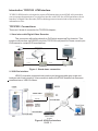
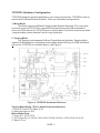
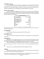
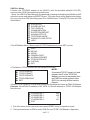
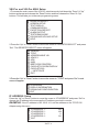
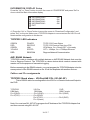
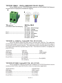
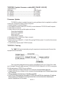
TCPIP232
Adapter
ATM TCP/IP Interface
Stand alone or with VSSI-Pro/VSIPro/VSI-Pro MAX
POS TCP/IP Interface
Stand alone
or with VSI-Pro /VSI-Pro Max
OPERATION MANUAL
June 2009
Introduction TCPIP232 ATM Interface.
TCPIP232 ATM Interface is designed to capture ATM transactions on and ATM LAN system then
convert caputered transactions to a serial port to interface with VSSI-Pro (ATM Synchronous Serial
Interface) or Digital Video Recorder (DVR) which supports text insertion and overlays trasaction
information to video.
TCPIP232 Connections
There are 2 kinds of connection for TCPIP232 Adapter;
1. Stand alone with Digital Video Recorder
This connection will inteface directly to DVR which supported Text Insertion. This
insertion will interface via RS232C only from TCPIP232 rear panel.So Please consult your
DVR manual or contact DVR manufacturer.
Monitor
Camera
Video Coaxial
Rounter/Network
CAT-5
Video Coaxial
Serial
CAT-5
TCPIP232
ATM
DVR
Figure 1. Stand alone connection
2. VSSI-Pro Interface
VSSI-Pro has also supported text insertion and programmable gray scale and
background of text inesertion. User are able to define the ATM IP Address via Onscreen
programming on VSSI-Pro Menu.
RS-232
Figure 2. VSSI-Pro Interface
PAGE 2
TCPIP232 Hardware Configuration:
TCPIP232 hardware operation depends on your network connection. TCPIP232 is able to
operate with HUB and Network Switcher. There are 2 hardware configurations:
1. Mirror Mode
This Mode supports HUB and Programmable Network Switchers. The user needs
to provide a port for TCPIP232 to capture ATM transactions on the HUB and needs to
mirror the ATM LAN port for TCPIP232 port to capture data. This kind of switcher we called
“ programmable network switcher” which is very expensive.
2. Tapping Mode.
The Tapping mode supports HUB and Typical Network Switcher. Tappping Mode
captures ATM transactions by tapping receiving data at the ATM only. So HUB and Switch
will not see TCPIP232 as a network device. see Figure 3
Figure 3. TCPIP232 Hardware Silkscreen
Tapping Mode Setup. (This is defualt from manufacturer)
1. Close JP7 and JP15. Open JP16
2. Open all jumper on JP6
Mirror Mode Setup
1. Close JP7, JP15, JP16
2. JP16 Close Pin1-2, Pin3-4, Pin5-6,Pin7-8,Pin9-10,Pin11-12,Pin13-14,Pin15-16
3. Take U17 out
PAGE 3
TCPIP232 Setups
The user must be careful to unplug the LAN cable from the ATM or POS. The ATM or
POS has the protection when there is no comunication between the ATM and Host Server in
limited time your ATM will be offline automatically. This peroid is called the “ATM Time Out’.
This time out depends on your ATM system. It is approximately 6-10 seconds.
Stand alone Setup
Connect the PC/DVR cable (021-037-SF) which comes from the TCPIP232 adapter
to your laptop. Power up your TCPIP232 and your laptop and run serial program like Hyper
Terminal at baudrate 19200,n,81 with VT100 emulation. Press ESC key (1BH) , [ (5Bh) and
P (50H) to enter to the Main Menu.
TCPIP232 SETUP
* IP ADDRESS
192.168.0.1
- INFORMATION 0
ON
- INFORMATION 1
ON
- INFORMATION 2
ON
- INFORMATION 3
ON
- INTERFACE
GENERIC
- ID
1
- SENSE
AUTO
- EXIT
Press Arrow key to move the cursor or change the configurations Press Enter key to select or
save the configurations.
IP ADDRESS
The IP address will be the same as the ATM or POS machine.
INFORMATION
This is a user define for additional information in the transaction to display special
information.
INTERFACE
Select Generic for stand alone mode if you connect with VSSI-Pro then select VSSI
for TCPIP232 will send raw data to VSSI-Pro to analyze the data but the VSSI-Pro is able to
use Generic mode by select TCPIP GENERIC when you program the VSSI-Pro.
Select REGCOM57600 or REGCOM9600 or VNET when you connect with RS485
network. Put jumper on JP9(1-2) , JP10(1-2) and JP11(1-2) for using AVE RS485 Network.
ID
Use when you select REGCOM57600 or REGCOM9600 or VNET.
SENSE
Select type of LAN cable for Straight Through or Cross Over cable if you select AUTO
then TCPIP232 will select cable type automatically.
Select EXIT and Unplug your PC/DVR Cable from your laptop and plug it to your DVR Com
port. Now your need to program your DVR to display text insertion.
PAGE 4
VSSI-Pro Setup
Connect the TCPIP232 adapter to the VSSI-Pro with the provided cable(021-010-SF),
connect video, ATM LAN and power up both units.
1.Enter the VSSI-Pro Main Menu by simultaneously pressing and holding the DOWN and UP
while then press and releasing RESET Button. The main menu will be displayed as below.
So move cursor to ATM Select by press UP or DOWN button. Press SET to enter the ATM
Select Menu.
ATM SELECT
SCREEN SETUP
TEXT DISPLAY
COMMUNICATION
EXCEPTION REPORT
ALARM OUTPUTS
TEST/DEMO MODE
DOWN/UP LOAD SETUP
HELP
2.On ATM Select Menu, Move cursor to TCPIP Interface then press SET to enter.
SDLC
BISYNC
ASYNC
CAMERA PORT
JOURNAL PRINTER
TCPIP INTERFACE
CUSTOM
EXIT
3.The Menu in TCPIP Interface will be displayed as below.
NOTE:
TCPIP GENERIC
If you select TCPIP Format I or II and
TCPIP FORMAT I
program the IP to the TCPIP232
TCPIP FORMAT II
Adapter you can not disconnect from
TCPIP DEBUGING
the VSSI-Pro and plug direct to the
EXIT
DVR. You can only do this is set for
Generic.
4.Select TCPIP GENERIC to enter and Change the IP Address the same as ATM’s IP Address.
Example, if the ATM’s IP address is 192.168.0.141 So the address on TCPIP-232 Adapter
this menu as:
IP ADDRESS 1 :
IP ADDRESS 2 :
IP ADDRESS 3 :
IP ADDRESS 4 :
EXIT
192
168
0
141
1. Exit off to return to the main menu then press RESET button to operation mode.
2. Test you transaction on ATM to verify VSSI-Pro and TCPIP-232 Adapter’s Operation.
PAGE 5
VSI-Pro and VSI-Pro MAX Setup
1.To access the main-menu of the VSI-Pro, simultaneously hold down the “Down” & “Up”
buttons and press and release the “Reset” button and then release the “Down” & “Up”
buttons. This will take you to the main programming menu.
REGISTER SELECT
SCREEN SETUP
TEXT DISPLAY
COMMUNICATION
EXCEPTION REPORT
ALARM OUTPUT
TEST/DEMO MODE
DOWNLOAD/UPLOAD SETUP
HELP
2.Press the “Up” or “Down” button to move the cursor to “REGISTER SELECT” and press
“Set”. The REGISTER SELECT menu will appear.
GENERIC
TCPIP
ADDRESSABLE VSI
AD4323
ADS
ANSI
BEETLE/50 PRINTERS
CASIO QT2100 REM DISPLAY
CASIO QT6000
----NEXT PAGE
EXIT
3.Press the “Up” or “Down” button to move the cursor to “TCPIP” and press “Set” to sub
menu will appear.
IP ADDRESS
DISPLAY INFORMATION
DOWNLOAD CONFIGURATION
EXIT
IP ADDRESS Setup
Press the “Up” or “Down” button to move the cursor to “IP ADDRESS” and press “Set” to
change the IP address to the same as the IP address you wish to monitor.
EXAMPLE: If the IP address is 192.168.0.141, set the address on the TCPIP 232
Adapter using this menu.
IP ADDRESS 1 :
IP ADDRESS 2 :
IP ADDRESS 3 :
IP ADDRESS 4 :
EXIT
PAGE 6
192
168
0
141
INFORMATION DISPLAY Setup
Press the “Up” or “Down” button to move the cursor to “IP ADDRESS” and press “Set” to
show or hide the Bank Information display.
INFORMATION 0
INFORMATION 1
INFORMATION 2
INFORMATION 3
EXIT
ON
ON
ON
ON
4.) Press the “Up” or “Down” button to move the cursor to “Download Configuration” and
press “Set” to execute. Make sure a TCPIP232 Adapter is connected and the VSI-Pro will
download the configuration to this device.
TCPIP232 LED Indicators
GREEN
RED
GREEN
YELLOW
RED
POWER
RECEIVE
LINK
SPEED
REGCOM
TCPIP-232 Power Status
TCPIP-232 Receive Data from ATM
ATM Status, On = Ready/OFF = Not ready
OFF = 10Mbps, On = 100Mbps Ethernet
Regcom Network Communication
AVE RS485 Network
TCPIP232 is able to interface with multiple devices on AVE RS485 Network that uses the
Vnet or Regcom Protocol. The TCPIP232 is a slave device which needs to connect with
master unit for the purpose of transaction logging.
Before connecting to the RS485 network, you must program the TCPIP232 Adapter to be the
same protocol of the RS485 network so the ID will not duplicate with another devices.
Cables and Pin assignments
TCPIP232 Stand alone - VSI-Pro(AVE P/N: 021-041-SF)
This is RS232 cable for sending data to the VSI-Pro in Generic mode and Output to
the DVR.
TCPIP232
VSI-Pro
DVR
DB9 Male
DB9 Male
DB9 Female
Pin-5(GND)-------------------------Pin-5(GND)----------------------------Pin-5(GND)
Pin-3(TXD)-------------------------Pin-2(RXD)
Pin-3(TXD)-----------------------------Pin-2(RXD)
Pin-1(Alarm)
Note: You must use 021-037-SF to program the IP Address of the TCPIP232 Adapter first
and then connect using 021-041-SF.
PAGE 7
TCPIP232 RS485 - VSI-Pro MAX(AVE P/N:021-139-SF)
This is RS485 cable for TCPIP232 Adapter connect to VSI-Pro MAX RJ45 Network
connections for the purpose of transaction logging.
TCPIP232
VSI-Pro MAX
2 Pin Removable Terminal plug
RJ45
Pin-1(NC) - White/Orange
Pin-2(NC) - Orange
Pin-3(NC) - White/Green
Pin-2-----------------------------------------Pin-4(+/A) - Blue
Pin-1-----------------------------------------Pin-5(-/B) - White/Blue
Pin-6(NC) - Green
Pin-7(NC) - White/Brown
Pin-8(NC) - Brown
TCPIP232 to VSSI-Pro Cable(AVE P/N: 021-010-SF)
This is the RS232 cable that users use to interface with VSSI-Pro. This cable also
provids alarm outputs to interface with alarm systems. and also includes the Serial output to
connect with DVR to get text insertion. This connection will also send the data to the DVR to
be used to search the video by searching from Text . This feature is for AVE or compatibly 3rd
party DVR only.
TCPIP232
VSSI-Pro
DVR
DB9 Male
DB9 Male
DB9 Female
Pin-5(GND)-------------------------Pin-5(GND)----------------------------Pin-5(GND)
Pin-2(RXD)-------------------------Pin-3(TXD)
Pin-3(TXD)-------------------------Pin-2(RXD)
Pin-8(CTS)-----------------------------Pin-2(RXD)
Pin-1(Alarm)
TCPIP232-PC/DVR Cable(AVE P/N: 021-037-SF)
This is and RS232 Cable to program the IP Address on TCPIP232 and then remove
and plug to the DVR to insert ASCII text on Video for stand alone application.
TCPIP232 Port
PC/DVR Port
DB9 Male
DB9 Female
Pin-5(GND)--------------------------------------------------Pin-5(GND)
Pin-2(RXD)--------------------------------------------------Pin-3(TXD)
Pin-3(TXD)---------------------------------------------------Pin-2(RXD)
PAGE 8
TCPIP232 Update firmware cable(AVE P/N:021-055-SF)
TCPIP232 Port
PC
DB9 Male
DB9 Female
Pin-5(GND)--------------------------------------------------Pin-5(GND)
Pin-4(DTR)---------------------------------------------------Pin-4(DTR)
Pin-2(RXD)--------------------------------------------------Pin-3(TXD)
Pin-3(TXD)---------------------------------------------------Pin-2(RXD)
Firmware Update
TCPIP232 is able to update firmware by using software that is supplied to qualified
customers. Contact the factory if this is required.
1. Install Update Firmware Software.
2. Use Update firmware cable (021-055-SF) connect between TCPIP232 and Computer.
2. Select Device from list.
3. Select Device form list and Set option as follows.
Flash Start 0x400000
Flash End 0x480000
Reset wait 250
Default Bank num 0x1
4. Select baud rate 115200 then Open comport.
5. Send Reset command.
6. Erase memory on Bank 40 , 41 and 42 by typing Z40 then press Y to confirm then erase
Bank 41 and 42.
7. Load file Boot System and TCPIP firmware.
TCPIP232 Testing
The TCPIP232 can be tested by using 2 computers in simulate mode.Connect the
equipment same as below.
This connecting diagram has no need to a Hub/Switch just use 1 Cross Over cable
and 1 Straight Through cable and use TCPIP232-PC/DVR Cable(021-037-SF) to program
IP Address same as TCPIP Server software.
1. Install TCPIP Client Tester software to the computer that simulates to be host
2. Install TCPIP Server software to the computer that simulating to be ATM that tapped data
by TCPIP232.
3. Set port Address for listening on TcpipServer(ATM).
4. Use TCPIP Client(Host) to send data to TCPIP Server(ATM) the destination IP address
and port same as TcpipServer configurations then connect and select datadump to
send to TcpipServer on File menu.
PAGE 9
LIMITED WARRANTY
(Terms and Conditions)
For 2 Years from the date of shipment, Seller warrants to Buyer that the Product is free from defects in
material or workmanship under normal use and service. Equipment manufactured by other than Seller
but furnished by Seller carries the same warranty to Buyer as Seller receives from the other manufacturer,
notwithstanding any provision to the contrary. If Buyer has specified a particular manufacturer’s product
which is not the brand standardly supplied by Seller, Buyer shall look only to the other manufacturer’s
warranty and Seller shall not warrant such item.
EXCLUSIONS. Seller’s warranty does not cover the following:
(1)
in-transit damage claims, improper handling by carrier or post office (Note: only the consignee of
the shipment can file a claim with the common carrier)
(2) damages caused by incorrect use, modification, carelessness, improper storage, hostile operating conditions, or unauthorized service, installation or repairs without proper training from the
Seller
(3) damages caused by fire, flood, lightning, collision, acts of God or other events beyond the
control of Seller
(4) products or parts thereof that have had serial numbers removed, altered or defaced
(5) products returned without an RMA number and sales or delivery receipt showing the date of
original purchase
(7) use of components that do not meet Seller’s specifications
(9) external parts such as cabinets or keypads
(10) periodic maintenance and adjustments resulting from normal use
WARRANTIES EXCLUDED, SELLER EXPRESSLY DISCLAIMS AND EXCLUDES ANY EXPRESS OR
IMPLIED WARRANTY OR MERCHANTABILITY OR FITNESS FOR A PARTICULAR PURPOSE WHICH
EXCEEDS OR IS INCONSISTENT WITH THE WARRANTY HEREIN EXPRESSLY SET FORTH.
NON-WARRANTY CLAIMS. In the event Buyer makes a warranty claim and Seller’s warranty does not
apply, Buyer shall reimburse Seller for all reasonable expenses incurred by Seller in diagnosing the installation/repair problem.
BUYER’S EXCLUSIVE REMEDIES. If the Product supplied shall fail to conform to the contract or any
applicable warranty, Buyer shall immediately notify Seller of such condition and afford Seller a reasonable
opportunity to inspect said Product. Seller shall, at its option, either repair or replace such nonconforming
Product. Seller shall not be responsible for labor charges for removal or installation of such equipment or
material or charges for transportation, handling and shipping except as provided in Seller’s written service
policy. No Product shall be returned without Seller’s prior written consent.
SELLER SHALL NOT BE LIABLE FOR ANY SPECIAL, DIRECT INCIDENTAL OR CONSEQUENTIAL
DAMAGES OF A COMMERCIAL NATURE ARISING OUT THE USE OF OR INABILITY TO USE SELLER’S
PRODUCT BY REASON OF THE FACT THAT SUCH PRODUCT DOES NOT CONFORM TO THE CONTRACT OR TO ANY EXPRESS OR IMPLIED WARRANTY. SELLER’S MAXIMUM LIABILITY SHALL BE
LIMITED TO THE COST OF REPAIR AND/OR REPLACEMENT OF THE PRODUCT CLAIMED TO BE
DEFECTIVE OR NONCONFORMING, SUBJECT TO SELLER’S RIGHT OF REMOVAL AND RETURN
OF PRODUCT.
All of the foregoing constitute Buyer’s sole and exclusive remedy and Seller’s sole and exclusive liability for
supplying nonconforming or defective Product.
PAGE 10
RETURNS. AVE products are fully inspected and carefully packed to ensure you are delivered a quality
product in good condition. If you are not fully satisfied with our product, returns of standard stocking items with
no restocking fee can be made within thirty (30) days of invoice to Buyer. All such returns must have prior
consent of Seller by obtaining an RMA number and must include the sales or delivery receipt showing the date
of original purchase and be in an unused condition contained in its original packaging. Any other returns must
have prior written consent of Seller and are subject to a restocking fee of fifteen percent (15%) and freight
charges.
RMA NUMBER. The RMA (Return Material Authorization) number must be obtained by contacting Seller prior
to the shipment of the the product for return. The RMA number is valid only for 15 days from the date of issue.
The RMA number must be clearly displayed on all shipping labels.
PAGE 11
ASIA
AVE (Thailand) Co., Ltd.
147 Soi On-Nut 44
Sukhumvit 77 Rd., Suan Luang
Bangkok, 10250 Thailand
Tel: 662-331-9364, 331-9285
Fax: 662-331-9365
Email: [email protected]
www.avethailand.com (English)
www.ave.co.th (Thai)
NORTH AMERICA
AVE USA
2000 West Governors Circle, Suite E
Houston, Texas 77092
Tel: 281-443-2300
Fax: 281- 443-8915
Email: [email protected]
www.americanvideoequipment.com
WESTERN EUROPE
AVE Multiview
Unit 1C, The Potteries,
Woodgreen Road, Waltham Abbey
Essex, EN9 3SA, UK
Tel: 440-870-770-9323
Fax: 440-870-770-9363
Email: [email protected]
www.multiview.net