1
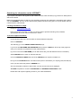
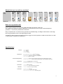
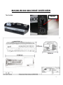
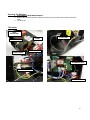
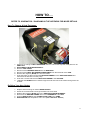
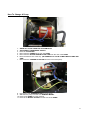
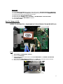
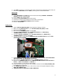
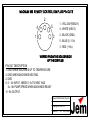
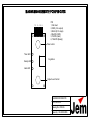
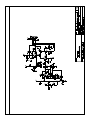
JEM Smoke Machine Training Program
INDEX
An Introduction To Smoke Technology:
Smoke Machine Markets
Smoke Machine Principles
CE Marking
Searching for information on the NET
Which fluid can I use with my machine?
What can my machine do?
Specifications
3
3
4
5
6
6
6
Service of machines:
Tools and optional extras
Machine Overview
Opening The Machine
Inside The Machine
8
9
10
10
How To…
How To Change A Heat Exchanger
How To Change A Pump
How To Change A PCB
Control PCB
Calibration
11
12
13
13
14
Spare Parts Lists:
Spare Parts 240V
Spare Parts 110V
15
16
Appendix:
Fuse Ratings
PCB Schematics
16
17
2
AN INTRODUCTION TO SMOKE TECHNOLOGY
Smoke Machine Markets
Jem / Martin smoke machines are categorised into 2 ranges: The Professional and the Club / DJ range.
If a product is branded as a “Martin” product this is aimed at the Club / DJ market.
All products branded as a “JEM” product are classed as Professional and are aimed at the higher end touring /
installation market.
All JEM / Martin Smoke products can be used across both of the different markets without any compromise of
performance or features.
Smoke machine principles:
All JEM / Martin conventional smoke machines utilise the same technology:
In Brief:
When the run button on the remote is pressed, smoke fluid is pumped from a removable container
situated within the machine via the flexible fluid pipe into an oscillating piston pump.
The fluid passes through the pump and enters the heat exchanger were the fluid is vaporised and
exits as thick, white smoke.
The heat exchanger is comprised of a heating element and a coil of copper or steel tubing between 3 and 6
metres in length. This is cast into a mass of aluminium.
The heat exchanger is heated via the heating element.
This is controlled by a J Type thermocouple fitted to the heat exchanger.
The temperature is determined by the calibration of the main control PCB.
Once the working temperature is reached, the main control PCB will allow the pump to be operated and the
machine will now be ready to run.
Haze machine principles:
The JEM ZR24/7 and Magnum Hazer work on the same smoke generation principles as the JEM / Martin
smoke machines.
The only difference is the smoke output on a hazer exits into a metal chamber where there is a fan creating a
fast moving air stream. This air stream disperses the smoke output and creates the haze.
Again the principles are identical to that of a conventional smoke machine.
There is a pump, heat exchange, PCBs and onboard controls. The major difference is the air chamber.
A radial fan is used with this system. It is used to allow the exiting smoke to have the maximum dispersal.
As with several of the smoke machines, the haze machine has a low fluid shut off system. This is an
electronic temperature control device that measures the temperature of the heat exchange over a short
period. If the temperature has not changed but the unit has been pumping; the unit will assume that the
system has run out of fluid and shut down. This prevents the system from running dry and burning out
the pump.
3
CE mark
All products that are produced by JEM / Martin carry the CE Certification.
These products meet the requirements of the following EC Standards and as such, comply with the EMC
(Electromagnetic Compatibility) and LVD (Low Voltage Directives), directives of the European Community:
EN 50 081-1 1992
Generic Emission Standard for domestic and light Industrial environments.
EN 50 082-1 1992
Generic Immunity Standard for domestic and light Industrial environments.
EN 60 335-1 1995
Safety of household and similar electrical appliances
These standards reference the following European standards:
Emissions:
EN 55 022 /B
RF voltage and field strength
EN 60 555
Harmonic current content
EN 55 014
RF voltage (discontinuous)
Immunity:
IEC 801-2
Electrostatic discharge to case
IEC 801-4
Common mode fast transients
These standards also meet the requirements of CISPR 22.
JEM did not carry the CE mark on products that were produced prior to 1995.
These products can be identified by either the DIN/XLR socket on the rear or top of the unit or the Mains PCB:
If the unit has a 5 pin DIN or a 4 pin XLR without the CE text on the rear, the unit is classed as NON-CE.
If the PCB has a 12 pin Molex connector fitted to it, this is classed as a NON-CE unit.
4
Searching for information on the INTERNET
If you require information with regards to JEM / Martin Smoke, Haze and Heavy Fog products an ideal place to
start is the Internet.
Martin has a dedicated team of staff who are constantly monitoring and updating the information that is placed
onto the INTERNET. This is to ensure that the best possible service is being given to not just dealers and end
users but also to internal staff.
Locating information is simple:
First go to: www.jemsmoke.com
Here you will find information on all of our current range of products including news, bulletins,
specifications and even videos of machines in action.
To access support information:
On the left hand side of the screen there are several different categories.
Click on SUPPORT.
This will bring you to the SMOKE USER SUPPORT page.
If you have a LOGIN NAME AND PASSWORD then press the LOGIN icon at the top of the page and
enter your username and password into the relevant boxes.
(If you do not have a LOGIN NAME you can still use the site, just with limited access to information)
Select SMOKE from the menu on the left hand side.
Go to the PRODUCTS MENU and choose the PRODUCT you require information on.
Now go to the CATEGORY menu and select which piece of information you require (parts,manuals, etc)
Once you have done this press the SEARCH icon.
All of the information relevant to the product you have chosen will now be displayed.
A LOGIN is required for access to TECHNICIAN and DISTRIBUTOR SUPPORT areas.
Please direct all inquires regarding access to your national distributor.
5
Which fluid can I use with my machine?
X=NO
O=YES
MAGNUM 800
Pro-Smoke
Studio
DX Mix
Pro-Smoke
Super
ZR Mix
Pro-Smoke
Highdensity SP
Mix
O
O
O
I-Fog
Reg. DJ
Fluid
O
Party Pack
O
X
Pro Haze
X
Heavy Fog
Fluid
B2 Mix
Heavy Fog
Fluid
C3 Mix
X
X
What can my machine do?
Dance clubs and discos the world over greatly appreciate this industry workhorse.
This reliable yet compact fog machine delivers a non-stop intense cover of fog for instant atmosphere
generation – a must for any mobile DJ or small club.
Easy to operate with a convenient carrying handle and portable design, the Magnum 800 uses the same high
technology standards found in the larger Magnum 2000.
The Magnum 800 is tough and rugged, the perfect fogger for small nightclubs, mobile DJs and bands. It is also
a useful fogger for parties and celebrations.
Specifications:
Physical
Performance
Control and Programming
Length: 410 mm
Width: 165 mm
Height: 170 mm
Dry weight: 6.5 kg
Max. smoke output (approx.): 200 m3 per minute
Max. operating time at full output (approx.): 38 mins
Operating time: Continuous, automatic level adjustment
Warm-up time: Approx. 7 minutes
Control options: Remote control (supplied) or DMX with optional DMX interface module
Remote control features: Instant or timer-controlled output, 0-100% adjustable output level
Fluid System
Fluid pump: Oscillating piston, high pressure
Onboard fluid capacity: 1 l
Max. fluid consumption at peak output: 50 ml per minute
Construction
Housing: Steel & aluminium
Heat exchanger: 750 W, direct thermal protection
Installation
Connections
Orientation: Floor (No Flying Kit Available)
Remote control: 5-pin DIN
Power connection: 3-pin IEC male socket
DMX (with optional DMX interface): 3-pin locking XLR
6
Electrical
Typical Power and Current
Thermal
AC power (EU models): 220-240 V nominal, 50 Hz
AC power (US models): 110-120 V nominal, 60 Hz
Main fuse (220-240 V power): 5 AT (slow blow)
Main fuse (110-120 V power): 10 AT (slow blow)
US model
110 V, 60 Hz: 820 W, 7.45 A
115 V, 60 Hz: 896 W, 7.79 A
120 V, 60 Hz: 975 W, 8.13 A
EU model
220 V, 50 Hz: 630 W, 2.86 A
230 V, 50 Hz: 689 W, 3.00 A
240 V, 50 Hz: 750 W, 3.12 A
Measurements made at nominal voltage. Allow for a deviation of +/- 10%.
Maximum ambient temperature (Ta max.): 40° C
Exterior surface temperature, steady state: 50° C
Max. nozzle temperature: 200° C
Approvals
EU safety: EN 50 081-1, EN 50 082-1
EU safety: EN 60 335-1 (1995)
Accessories
Ordering Information
Service Info (internal only - do not publish)
Pro Smoke Studio (DX Mix) fluid, various sizes available
Pro Smoke Super (ZR Mix) fluid, various sizes available
Pro Smoke Super (Fragranced) fluid, various sizes available
Pro Smoke High Density (SP Mix) fluid, various sizes available
I-fog fluid, various sizes available
Ducting Kit (Including adapter and 5m of 4-inch (104mm) ducting): P/N 92625004
DMX Interface ZR12: P/N 92765015
Martin Magnum 800, 110 V: P/N 92220001
Martin Magnum 800, 240 V: P/N 92220000
Cooling time before service or maintenance: 15 minutes
Minimum clearance around air vents: 0.20 m
7
SERVICE OF MACHINES
TOOLS AND THINGS:
For successful servicing of a machine you will need some basic tools which are in good working order
and the right size for the job. Other tools / equipment are available for specific jobs but in most cases these are
not needed for general service.
Equipment needed:
Screwdrivers
Pozidrive, size 1 and 2
Flat tip, size small and medium
Wrenches
7mm
12mm x2
Pliers
Needle Nose, small
Wire Cutters, small
Digital Multi Meter (With ability to measure mV)
Additional Items / recommended:
Cable Ties (p/n 13104000)
Silicone Sealant
JEM Calibration Box (p/n 92620005)
Paper towels (or other absorbent material)
Ammeter (For measuring current draw of machine – could be handheld or bench mounted)
Epsilon 5 Portable ISP Programmer (p/n 50502004)
Common Sense !!
WARNING – MAINS VOLTAGE
DISCONNECT FROM MAINS SUPPLY
BEFORE REMOVING COVERS
AND SERVICING THIS MACHINE
PROCEED WITH EXTREME CAUTION
8
MAGNUM 800 MACHINE OVERVIEW
The Outside:
ANALOGUE
CONTROL
9
Opening The Machine:
1. DISCONNECT FROM MAINS SUPPLY.
2. Remove the 6 M4x10 pozidrive TAPTITE screws from the outside of the machine and store
safely.
3. Lift off the lid.
The Inside:
HEAT
EXCHANGE
PUMP
THERMAL TRIP
EARTH POINT
FLUID LINE
ELEMENTS
THERMOCOUPLE
BRASS FITTINGS
MAINS INPUT
10
HOW TO….
REFER TO SCHEMATICS / DIAGRAMS IN THE APPENDIX FOR MORE DETAILS
How To Change A Heat Exchange:
1. Always try to change a HEAT EXCHANGE when it is cold as the exposed metal parts can be
VERY HOT.
2. DISCONNECT FROM MAINS SUPPLY.
3. Remove TOP COVER.
4. Disconnect the THERMOCOUPLE from the MAIN PCB.
5. Disconnect the HEAT EXCHANGE POWER WIRES from the terminals of the PCB.
6. Remove the negative (BLUE) wire from the heater.
7. Undo the brass nut that connects the BRASS ASSEMBLY to the HEAT EXCHANGE and
disconnect the fluid line from the pump.
8. Undo the 4 screws that hold the HEAT EXCHANGER to the CHASSIS.
9. Withdraw the NOZZLE of the heater through the hole and remove the heat exchange from the
chassis.
Refitting Your New Heater:
1.
2.
3.
4.
5.
6.
Replace heat exchange in chassis NOZZLE FIRST.
Screw the 4 screws back in through the bottom of the chassis
Replace the negative (BLUE) wire to the HEAT EXCHANGER ELEMENT.
Reconnect the HEATER POWER wires to the TERMINALS of the PCB.
Using a NEW OLIVE refit the COPPER FLUID LINE to the PUMP.
RECALIBRATE the temperature of the unit. (See Calibration Section)
11
How To Change A Pump:
1.
2.
3.
4.
5.
6.
DRAIN ALL FLUID FROM THE SYSTEM FIRST.
DISCONNECT FROM MAINS SUPPLY.
Remove TOP COVER.
Disconnect the POWER wires from the PUMP.
Disconnect the BLACK RUBBER FLUID LINE from the rear of the PUMP.
Move the fluid line out of the way. (BE CAREFUL OF FLUID COMING BACK DOWN THE
PIPE)
7. Disconnect the COPPER FLUID LINE from the front of the pump.
8.
9.
10.
11.
Unhook the rear RUBBER MOUNT from the pump.
Withdraw the pump from the front RUBBER MOUNT.
Remove the PUMP from the machine.
Remove the BRASS FITTING from the front of the PUMP.
12
REFITTING:
12.
13.
14.
15.
16.
17.
18.
Fit the BRASS FITTING to the front of the pump using a THREAD SEALANT COMPOUND.
Fit the new PUMP to the CHASSIS by inserting the front end first into the RUBBER MOUNT.
Hook the rear mount onto the back of the pump.
Reconnect the BLACK RUBBER PIPE.
Reconnect the POWER wires to the PUMP – BROWN INSIDE / BLUE OUTSIDE.
Turn machine on and RE-PRIME the system.
Refit TOP COVER.
How To Change A PCB:
REFER TO SCHEMATICS / DIAGRAMS IN THE APPENDIX FOR MORE DETAILS
PCB
1. DISCONNECT FROM MAINS SUPPLY.
2. Remove TOP COVER.
3. Remove the 2 screws at the bottom of the PCB HEATSINK from INSIDE THE HEATER
COMPARTMENT.
4. Disconnect the PCB WIRING LOOMS from the PCB (Note orientation before removal).
5. Remove the 2 PLASTIC RIVETS from the 5-pin din socket.
13
6. The PCB is mounted on 2 mounting posts which will need to be squeezed to remove the pcb.
7. Remove the HEATSINK from the PCB by removing the 2 screws/nuts/washers.
REFITTING:
8. Fit the HEATSINK to the PCB using the 2 screws/nuts adding THERMAL TRANSFER
PASTE underneath component Q6.
9. Fit new PCB to the mounting posts.
10. Insert the 2 PLASTIC RIVETS into the din socket.
11. Insert the 2 screws into the heatsink from the heater compartment.
12. Reconnect the PCB WIRING LOOMS (Observe polarity).
13. Refit the TOP COVER.
Calibration:
1.
2.
3.
4.
5.
Set the JEM CALIBRATION BOX to the required mV setting (13.4mV).
Make sure the RAMP BUTTON on your CALIBRATION BOX (GREY) is OFF.
Remove the TOP COVER.
Disconnect the THERMOCOUPLE from the PCB.
Connect the RED TERMINAL of the CALIBRATION BOX to the POSITIVE (+)
THERMOCOUPLE connector of the PCB.
6. Connect the BLACK TERMINAL of the CALIBRATION BOX to the NEGATIVE (-)
THERMOCOUPLE connector of the PCB.
7. Turn the machine on and tweak the TEMPERATURE CALIBRATION POT until the RED
(HEATING) LED FLASHES.
8. IF YOU PRESS THE RAMP BUTTON IN THE LED SHOULD GO OUT AND COME BACK
ON AGAIN WHEN YOU RELEASE THE BUTTON.
9. Disconnect the CALIBRATION BOX from the THERMOCOUPLE connectors.
10. Replace the THERMOCOUPLE onto the DMX/PROGRAM PCB (PRE 11/06: YELLOW = +
BLUE = - / POST 11/06: BLACK = + WHITE = -)
11. Turn the machine on and check for current draw.
12. Let the machine heat up and check using a digital volt meter that the RED (HEATING) LED
turns OFF at the correct point.
13. The GREEN (OK) LED should turn on about 1mV lower than the peak temperature setting.
(RED LED TURNING OFF)
14. TEMPERATURE CALIBRATION IS NOW COMPLETE.
14
SPARE PARTS LISTS
240V
Part
PUMP
PCB
Description
PUMP
MAIN
Spare Part Number
05761003
62020005
PCB
HEAT
EXCHANGE
HEAT
EXCHANGE
HEAT
EXCHANGE
REMOTE
62020008
COMPLETE
Comments
240V RED BODY (LARGE)
MAIN CONTROL PCB - TESTED
TESTED w/o BUTTON TOPS OR
KNOBS
COMPLETE BUILT UP HEAT
EXCHANGE c/w BRASS FITTINGS
BARE EXCHANGE (No insulation
or casework) c/w BRASS FITTINGS
BARE Inc BRASSWORK
26400630
BRASSWORK ONLY
26460030
CASEWORK
n/a
BRASS FITTINGS ONLY
CASEWORK AVAILABLE
SEPARATELY - CONTACT [email protected]
INSULATION
26520010
PRE CUT INSULATION KIT
TRIP SWITCH ONLY
TRIP SWITCH INCLUDING HARD
WIRED LOOM
PLASTIC CARRY HANDLE
TOP LID / COVER
MAIN CHASSIS - BARE
9.5L FLUID BOTTLE
COMPLETE REMOTE CONTROL
CLEAR FLUID LINE
MAINS ON/OFF SWITCH
ALL WIRING LOOMS FOR
MACHINE
ALL STICKERS / LABELS FOR
MACHINE
HEAT
EXCHANGE
HEAT
EXCHANGE
HEAT
EXCHANGE
HEAT
EXCHANGE
CASEWORK
CASEWORK
CASEWORK
OTHER
OTHER
OTHER
OTHER
THERMAL TRIP ONLY
05041021
THERMAL TRIP Inc LOOM
CARRY HANDLE (PLASTIC)
TOP COVER
MAIN CHASSIS
BOTTLE
REMOTE CONTROL
FLUID LINE
MAINS SWITCH
19200050
26560150
26560140
34300001
92765000
56220011
05523002
OTHER
WIRING LOOMS COMPLETE
OTHER
STICKERS COMPLETE
15
110V
Part
PUMP
Description
PUMP
Spare Part Number
05761001
PCB
MAIN
62020007
PCB
HEAT
EXCHANGE
HEAT
EXCHANGE
HEAT
EXCHANGE
REMOTE
62020008
Comments
110V BLACK BODY (LARGE)
110V MAIN CONTROL PCB TESTED
TESTED w/o BUTTON TOPS OR
KNOBS
COMPLETE BUILT UP HEAT
EXCHANGE c/w BRASS FITTINGS
BARE EXCHANGE (No insulation
or casework) c/w BRASS FITTINGS
COMPLETE
BARE Inc BRASSWORK
26400820
BRASSWORK ONLY
26460030
CASEWORK
n/a
BRASS FITTINGS ONLY
CASEWORK AVAILABLE
SEPARATELY - CONTACT [email protected]
INSULATION
26520010
PRE CUT INSULATION KIT
TRIP SWITCH ONLY
TRIP SWITCH INCLUDING HARD
WIRED LOOM
PLASTIC CARRY HANDLE
TOP LID / COVER
MAIN CHASSIS - BARE
9.5L FLUID BOTTLE
COMPLETE REMOTE CONTROL
CLEAR FLUID LINE
MAINS ON/OFF SWITCH
ALL WIRING LOOMS FOR
MACHINE
ALL STICKERS / LABELS FOR
MACHINE
HEAT
EXCHANGE
HEAT
EXCHANGE
HEAT
EXCHANGE
HEAT
EXCHANGE
CASEWORK
CASEWORK
CASEWORK
OTHER
OTHER
OTHER
OTHER
THERMAL TRIP ONLY
05041021
THERMAL TRIP Inc LOOM
CARRY HANDLE (PLASTIC)
TOP COVER
MAIN CHASSIS
BOTTLE
REMOTE CONTROL
FLUID LINE
MAINS SWITCH
19200050
26560150
26560140
34300001
92765000
56220011
05523002
OTHER
WIRING LOOMS COMPLETE
OTHER
STICKERS COMPLETE
APPENDIX
Fuse Ratings
Fuse
240V
110V
Internal
6.3A
10A
16
MAGNUM 800 REMOTE CONTROL DIN PLUG PIN OUTS
2
4
1 - YELLOW (READY).
5
4 - WHITE (HEAT).
3
1
2 - BLACK (GND).
5 - BLUE (0 - 10v)
3 - RED (+16v).
VIEWED FROM THE SOLDER SIDE
OF THE DIN PLUG
PIN OUT DESCRIPTION
1, GND WHEN MACHINES UP TO TEMPERATURE
4, GND WHEN MACHINES HEATING
2, GND
5, 0 - 10v INPUT, NEEDS 1.5v TO HEAT AND
2v -10v PUMP SPEED WHEN MACHINES READY
3 +16v OUTPUT
Magnum 800 Remote Plug Pin
Drawing No. 2000-1A
Drawn by :
GS
28/03/2006
MAGNUM 800 REMOTE PCB PIN OUTS
1 2 3 4 5 6
PIN
1, Not Used
2, RED (+16v output)
3, BLUE (0-10v input)
4, BLACK (GND)
5, WHITE (Heat)
6, YELLOW (Ready)
Timer control
Timer LED
Ready LED
Fog button
Heat LED
Output Level Control
MAGNUM 800 REMOTE
PCB PIN OUTS
Drawing No. 2000-2A
Drawn by : GS 28/03/2006
NO OUTPUT
YES
Is the
machine fully
heated and
ready to run?
Is the machine
plugged in, turned on
at the mains AND the
power switch set to
ON?
NO
Check power
and turn on
NO
See HEATER PROBLEMS
YES
Is the pump
running?
NO
See PUMP PROBLEMS
YES
Undo the brass fitting to the heater / fluid line and run the machine.
Is fluid coming out of
the brass fitting?
NO
YES
Pump seized – Replace pump
Heater is blocked – Replace heater
PUMP PROBLEMS
Is power getting to the pump?
(set to full power and check 240V / 110V)
NO
See PCB PROBLEMS
YES
Does piston seem to
be moving?
NO
PUMP SEIZED - REPLACE
YES
Is fluid travelling
through pump?
NO
PUMP BLOCKED - REPLACE
YES
Fault may be in fluid line / heater
HEATER PROBLEMS
YES
NO
Is the heater heating?
Overheating
YES
YES
Check thermocouple
OK?
CHECK
CALIBRATION
NO
Is power getting to the heater?
(check 240V / 110V)
REPLACE
HEATER
NO
YES
See PCB
PROBLEMS
Is power getting to the
thermal trip?
(check 240V / 110V)
NO
YES
YES
Is power getting through
the thermal trip?
(check 240V / 110V)
THERMAL TRIP
FAULT – RESET /
REPLACE
NO
Disconnect power and remove power loom from element connectors
Measure across the elements for continuity and check for earth leaks
Normal Ohms reading?
NO
Earth leakage?
YES
YES
OPEN CIRCUIT
HEATER REPLACE
See PCB
PROBLEMS
OPEN CIRCUIT
HEATER REPLACE
See PCB
PROBLEMS
NO
PCB PROBLEMS
APART FROM THE OBVIOUS FUSES /
WIRING ETC. PCB FAULT FINDING IS
TOO IN-DEPTH TO COVER HERE –
PLEASE REFER SERVICING / REPAIR
TO A QUALIFIED ENGINEER