1
User Guide
MKP-160
Keyprox User's Guide
Quick Reference Guide
3
1
5
2
29
28
25
27
26
23
24
8
9
10
6
7
6
7
16
11
12
6
7
15
14
13
19
17
4
21
20 18
19
22
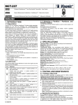
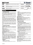
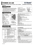
1. Present Prox Tag
2. Volume indication
3. System status
(NOT READY/BYPASS)
4. Volume-level, Zone #,
PGM / X-10 display
5. PGM / X-10 indication
6. Partition status indication
7. Partition Selection
8. DISARM
9. ARM HOME / QUICK ARM HOME
10.ARM AWAY / QUICK ARM AWAY
11.LATCHKEY
12.Mute exit beeps
13.Volume control
14.Show next status of
open / bypass zones
15.PGM/X-10
16.INSTANT
17.FIRE
18.EMERGENCY
19.PANIC: Press both keys
simultaneously for 2 seconds
20.AUX / Enroll MKP-160 /
Back to factory / Cancel
current operation
21.Control panel messages
22.Installer Mode
23.Memory / Alarm
24.Trouble
25.AC failure
26.Communication failure
27.Low battery
28.Status when Partition is
disabled
29.LED (green and red)
MKP-160
Touch Screen Keyprox
User’s Guide
Table of Contents
1. INTRODUCTION ..............................................................................................................2
2. INSTALLATION ................................................................................................................3
2.1 Inserting Battery ..........................................................................................................3
2.2 Closing Battery Compartment Cover ..........................................................................3
2.3 Wall Mounting Options................................................................................................4
2.4 Enrolling the MKP-160 ................................................................................................9
2.5 Configuring the MKP-160 Parameters ........................................................................9
2.6 Enrolling Proximity Tags ...........................................................................................10
3. USING THE TOUCH SCREEN KEYPROX ....................................................................12
3.1 Arming and Disarming the System ...........................................................................12
3.2 Initiating Alarms ........................................................................................................13
3.3 System Status and Indications .................................................................................13
3.4 Bypassing Zones ......................................................................................................16
3.5 Controlling Home Automation Devices .....................................................................16
3.6 Other Functions ........................................................................................................17
APPENDIX A: SPECIFICATIONS ......................................................................................18
APPENDIX B: COMPLIANCE WITH STANDARDS ...........................................................19
D-303503 MKP-160 User's Guide
1
1. INTRODUCTION
MKP-160 is a 2-way wireless PowerCode touch screen keyprox for the PowerMax family
control panels. The MKP-160 enables most common everyday user functions:
• Arm and Disarm the alarm system.
• Initiate Emergency, Fire and Panic alarms.
• Control home automation devices.
• Review system status.
• Perform programmable predefined functions.
MKP-160 is operated by proximity tags. When authorization is required the user presents a
valid proximity tag to the built-in tag reader.
In addition, the MKP-160 supports panels featuring Partitions. Partitioning allows you to
select up to three controllable areas; each partition can be armed and disarmed
independently regardless of the status of the other two partitions by the same or different
users (see keys marked "7" in the "Quick Reference Guide").
The MKP-160 can be wall-mounted using the supplied bracket or be used as a desktop unit.
For compliance with various international standards, the MKP-160 is equipped with two
tamper switches that can be defined to detect when the cover of the battery compartment is
removed or when the unit is removed from its mounting bracket.
Other features of the MKP-160 include:
• Easy-to-use intuitive graphical touch user interface
• Employees can use their standard RFID access cards with the MKP-160.
• Proximity-tag operated, no need for user to remember codes
• Allows all users' every day actions
• Panel can be installed in hidden location
• 2 per system, suitable for any installation
• Status, Alarm, Memory, Trouble and Ready indications.
• Automatic reporting of low battery.
• Back lighting.
• Audible and visual exit/entry warning beeps
• MKP-160 enables using proximity tags regardless of whether or not the control panel has
a proximity tag reader.
• Long battery life expectancy (for typical use).
• Trouble beeps
2
D-303503 MKP-160 User's Guide
2. INSTALLATION
2.1 Inserting Battery
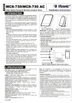
CAUTION!
Risk of explosion if
battery is replaced
by an incorrect type.
Dispose of used
battery according to
manufacturer's
instructions.
Figure 1 – Battery Insertion
Insert two 1.5V batteries in each slot while ensuring battery polarity.
2.2 Closing Battery Compartment Cover
Desktop Installation (Using Battery Cover without Tamper Hole)
2
1
Figure 2 - Battery Cover Mounting (part a)
D-303503 MKP-160 User's Guide
3
Wall-mounted Installation [Via Battery Cover without Tamper Hole (see "A")]
Figure 3 - Battery Cover Mounting (part b)
A. Tamper
B. DC Power Connection – use supplied cable in addition to batteries
C. Wiring channel for wall installation
Note: The DC cable is available in specific models
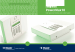
2.3 Wall Mounting Options
The MKP-160 unit mounting options are illustrated in the following drawings.
Wall Mounting
Figure 4 – Wall Mounting
1. Drill 3 mounting holes
3. Attach the unit to the bracket
2. Position the bracket and secure with 3 screws
4. Secure the unit with the screw
A. Hole for DC power source cable installed in wall
4
D-303503 MKP-160 User's Guide
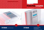
Wall Mounting with External DC Cable
1. Hold the power source cable from the wall and
thread it through its hole in the bracket
A. Hole for DC power source cable installed in wall
2. Drill 2 mounting holes and then
secure bracket with 2 screws
B. Hole for tamper
WARNING! The power source (optional) must be 5 - 12VDC.
D-303503 MKP-160 User's Guide
5
3. Insert screwdriver into slot and lift
upward to separate the battery
compartment cover from the front cover
4. Connect together the power source cable
and the DC cable connector (supplied).
Note: The DC cable connector is available in
specific models
C. DC Power Cable Connection
6
D-303503 MKP-160 User's Guide
5. Connect the DC cable connector to the
DC power connection.
Note: You can connect the DC cable
directly, as shown in the top drawing, or via
one of the wiring inlets indicated by the
arrows.
D-303503 MKP-160 User's Guide
6. Align the bracket pins with their
respective slots.
7
7. Push the MKP-160 unit downward on the
bracket
8. Secure the unit with the screw
Figure 5 – Wall Mounting with External DC Cable
Desk mount
1. Insert the bracket pins into
the corresponding slots.
Figure 6 – Desk mount installation
8
D-303503 MKP-160 User's Guide
2.4 Enrolling the MKP-160
A flowchart of the MKP-160 enrolling procedure is provided below.
Step
Action
LCD Display
1
Enter the Installer menu and select
“2:ENROLLING”
2.ENROLLING
2
Select "ENROLL WL LCD KP" Option
See Note
ENROLL WL LCD KP
3
When "lcd kp No :" appears on the
control panel display, enter the
keyprox number, for example
"lcd kp No : 2".
lcd kp No :
4
Enroll the device by pressing the
(AUX) button for about 5
lcd kp No : 2
TRANSMIT NOW
seconds until the LED turns ON and
then release the button.
5
The control panel displays the
number of the enrolled device.
6
Configure the MKP-160 Keyprox
means scroll
arm stn No: 2
See section 2.5
and select
Note: If the MKP-160 is already enrolled, you can configure the MKP-160 parameters via the
“16.DEFINE ARM ST” main menu.
2.5 Configuring the MKP-160 Parameters
Enter the 16.DEFINE ARM ST main menu in the PowerMax control panel, choose the
number of the touch screen keyprox device to configure and follow the configuration
instructions for the MKP-160 touch screen keyprox.
Option
Configuration Instructions
Enabling the function will enable a tamper open / close message.
TAMPER TYPE
Options settings: disable (default) and enable.
SCREEN SAVER
Enabling the function will turn off the display if no key is pressed
for more than several seconds. Tapping on the MKP-160 keyprox
will return the device to normal display.
Options settings: disable (ac) (default) and enable.
SHOW AC FAILURE
Enable/disable AC failure indication on the keyprox device.
Options settings: disable (default) and enable.
D-303503 MKP-160 User's Guide
9
SUPERVISION
Define whether or not the control panel will monitor supervision
messages sent by the keyprox.
Options settings: disable and enable (default).
EXIT-ENTRY BEEPS
Define whether or not the keyprox will sound the exit and entry
beeps or whether the keyprox will sound the beeps only when the
system is armed AWAY and not when it is armed HOME.
Note: When the screen saver is active during an exit/entry delay,
the MKP-160 device will not sound exit-entry beeps (exit-entry
beeps are sounded only through the control panel during this
time). If the MKP-160 returns to normal display during the
entry/exit delay, it will continue to sound the exit-entry beeps until
the next time the screen saver is activated or until the end of the
exit/entry delay, whichever first.
Options settings: off (default); off when home and on.
SOUNDER VOLUME
Define the volume level of the sounder.
Options settings: low, mid (default) and high.
SHOW MEM/TRBL
Define if Trouble or Memory events in the control panel will be
indicated on the LCD keyprox.
Options settings: enable (default) and disable.
2.6 Enrolling Proximity Tags
You can enroll proximity tags in the PowerMax control panel either through the MKP-160
touch screen keyprox, as described below, or through the PowerMax control panel, as
described in the corresponding section of the control panel's User or Installer Guide.
Each proximity tag corresponds to its User Code. Therefore, be sure that a corresponding
User Code is programmed for each enrolled proximity tag (code "0000" is not allowed). For
example, "Tag no : 2" must be assigned to User Code 2 and " Tag no : 8" must be assigned
to User Code 8. Partition authorization of each proximity tag is identical to that of the
corresponding User Code. For example, if User Code 3 is set to Partitions 1 and 3,
"Tag no : 3" will also be set to Partitions 1 and 3.
Enrolling Proximity Tags in the PowerMax Panel through the MKP-160 Keyprox
Step
1
Action
LCD Display
Enter the Installer menu of the control panel and
go to “2.ENROLLING
2.ENROLLING”
2.ENROLLING
2.ENROLLING
2
Select "ENROLL PROX TAG" Option
ENROLL PROX TAG
3
Select the Prox Tag number for enrollment
Tag no :
Tag no : 8
10
D-303503 MKP-160 User's Guide
Step
4
Action
LCD Display
When "PRESENT
PRESENT TAG"
TAG is displayed, press the
AWAY key (
PRESENT TAG
) on the MKP-160. The
AWAY key and the Present Prox Tag key (
)
begin to blink
5
Present the proximity tag to the MKP-160 within
the 5 second timeout period. If the enrollment is
successful, the display reads the selected Prox
Tag number followed by a box.
D-303503 MKP-160 User's Guide
Tag no : 8 11
3. USING THE TOUCH SCREEN KEYPROX
3.1 Arming and Disarming the System
Step
Operation
User Actions
(1)
Select a PARTITION
(if Partition is enabled)
2
Arm AWAY
Optional
1
Arm HOME
Keyboard &
Panel Response
The selected
Partition blinks.
Any combination of
(2)
+
[
]
(2)
Disarm (OFF)
+
[
]
(2)
+
[
]
(≈ 2 sec.)
(2) (3)
Quick arm HOME
(If Quick Arm is enabled)
Optional
3
INSTANT
(≈ 2 sec.)
(After arming HOME/
AWAY)
LATCHKEY
(5) (7)
(After arming
AWAY)
(4)
(4)
(2) (3)
Quick arm AWAY
(If Quick Arm is enabled)
(4)
(6) (7)
The selected key and
the "Present Prox
Tag" icon (
)
begin to blink and
prompt you to present
your Tag (except for
Quick Arm).
The keyprox's LED
blinks red once to
indicate transmission
of the arming
command to the
control panel.
The LED and the
buzzer then indicate
the control panel's
response – see
“System Status
and Indications”
section 3.3.
Notes:
1. If Partition is disabled at the control panel, skip Step 1.
2. If Partition is enabled at the control panel and a partition was not selected in Step 1,
Step 2 will activate all of the partitions assigned to the user.
3. The Quick arm functions only if enabled at the control panel.
4. If the action is not completed while the selected arming key is blinking, the desired
function will not be executed.
5. Press the INSTANT key within maximum 8 seconds timeout period after completing the
previous step. This will delete the entry delay for the current arming session.
• INSTANT is available only if supported in the PowerMax control panel (refer to the
PowerMax Installer Guide).
6. For LATCHKEY activation, press the LATCHKEY key within maximum 8 seconds
timeout period after completing the previous step.
12
D-303503 MKP-160 User's Guide
7.
LATCHKEY is available only if the LATCHKEY feature is enabled in the PowerMax
control panel (see PowerMax Installer Guide).You can perform the LATCHKEY and
INSTANT functions, one after the other. The order is not important.
• LATCHKEY and INSTANT functions can be operated only during exit delay.
• While in INSTANT / LATCHKEY, the small circle icon on the upper right side of the
INSTANT / LATCHKEY icon lights.
3.2 Initiating Alarms
Alarms
Emergency
alarm
Actions
Response
See section
3.3.
(≈ 2 sec.)
Fire alarm
See section
3.3.
(≈ 2 sec.)
Panic alarm
See section
3.3.
(≈ 2 sec.)
Notes
When pressing the Fire or
Emergency icons, the MKP-160
starts beeping. After pressing the
button for approx. 2 seconds, the
MKP-160 sends the command.
When pressing the Fire and
Emergency icons together, the
MKP-160 starts beeping. After
pressing the button for approx. 2
seconds, the MKP-160 sends the
Panic command.
3.3 System Status and Indications
When executing a command, the MKP-160's LED ("29" in the "Quick Reference Guide")
blinks red once to indicate transmission of the command to the control panel. If the operation
is successfully completed, the green LED lights momentarily and a "happy tune" sounds.
If the operation fails or cannot be completed, for example, when the system is "Not
Ready", the red LED lights steadily and a "sad tune" sounds.
Buzzer Indication
Happy
(success) tune
Sad (failure) tune
None
LED Indication
Panel Response
Momentary GREEN
Success: Operation is
successfully completed
Momentary RED
Fail: Operation failed or
invalid key press
None
No communication:
Control panel does not
respond.
D-303503 MKP-160 User's Guide
13
Arming Indications
The table below lists the Arming indication keys and their definition.
Icon/Key Indications
Arming Indication
ARM AWAY
ARM HOME
DISARM
EXIT DELAY
(followed by)
(followed by)
ENTRY DELAY
+
the "Present Prox Tag" icon and
DISARM key blink simultaneously
If Partition is enabled, the corresponding (house) icon is displayed according to partition state.
General Indications
The Ready/Not Ready, Alarm Memory, Trouble and Low Battery indications are provided via
the indications in the following table:
Number
Indication [1]
What it Means
Instructs the user to present the RFID proximity
tag in order to initiate a command.
Volume control mode.
System is NOT READY; one of the zones is not
secured. You cannot arm the system before the
zone is secured or bypassed.
System is READY but one or more zones are
bypassed.
No indication
System is READY and all zones are secured.
+
Bypassed (
) or Open (
) Zone number
Selected PGM or X-10 unit number.
/
+
+
14
Volume level
D-303503 MKP-160 User's Guide
Number
Indication [1]
What it Means
PGM/X-10 control mode.
System is armed in LATCHKEY mode.
Exit beeps are shut off. This mode disables
when the exit delay is over. [2]
System is armed in the INSTANT mode.
A message is waiting in the system.
The control panel is presently in "INSTALLER
MODE" or "USER SETTINGS".
Memory / Alarm in partition or system.
The partition / system has an active trouble
status that needs to be reviewed and cleared. [3]
AC failure.
Communication failure: MKP-160 is out of range
of the control panel or did not get an
acknowledge signal of a command from the
control panel.
Indicates that the MKP-160 device's battery is
low and must be replaced (see section 2.1).
[1] The key indication is displayed after the first red LED blinks indicating the status request.
[2] Operates only during Exit Delay.
[3] See respective sections in the control panel's User and Installer's Guides.
[4] If there is more than one status indication at a single time, the keys are displayed
simultaneously.
Zone Status Indications
To view the zone numbers of enrolled detectors that are in NOT READY (
) or
BYPASSED state (
), repeatedly press the
key. Upon each press of the
key,
the next zone number appears on the Zone # display (marked "4" in the "Quick Reference
Guide").
To view the zone numbers that are assigned to a Partition, press the desired Partition
number (
/
/
) followed by the
key. Upon each press of the
key, the
next zone number assigned to the pressed Partition number appears on the Zone # display.
D-303503 MKP-160 User's Guide
15
Notes:
A zone which is BYPASSED and NOT READY is shown as BYPASSED (
).
When "00" appears on the Zone # display, this indicates a NOT READY state in the alarm
system that is not related to any detector, for example, "tamper open" in a keypad or control
panel.
If all zones are READY and "not bypassed", the
button is disabled.
3.4 Bypassing Zones
A zone can by bypassed by pressing the
key until the zone number is shown on the zone #
display (marked "4" in the "Quick Reference Guide") followed by the
key.
Note: Zone bypassing on the MKP-160 unit can be operated only if Bypass was enabled via
the control panel (see PowerMax Installer Guide).
3.5 Controlling Home Automation Devices
To operate home automation devices, see the table below.
Note: Make sure that the relevant PGM and X-10 outputs are configured correctly; refer to
the “OUTPUTS” menu in the control panel’s Installer Guide.
Step
X-10 device ON
1
PGM device ON
X-10 or PGM
device OFF
X-10 or PGM
device TOGGLE
(~2sec)
2
…
[1 to 15]
…
[P0]
[PGM P0] or
1 to 15]
[X-10
[PGM P0] or
1 to 15]
[X-10
3
The keyprox's LED blinks red once to indicate transmission of the command to the control
panel. The LED and the buzzer then indicate the control panel's response – see “System
Status and Indications” in section 3.3.
Note:
• Long press (more than 2 sec.) of the
button initiates the X-10 function and the
PGM/X-10 display (marked "4" in the "Quick Reference Guide") will read "01". This
number is incremented by 1 upon each press of the
• Short press of the
read "P0" with the
16
key.
button initiates the PGM function and the PGM/X-10 display will
key.
D-303503 MKP-160 User's Guide
3.6 Other Functions
Output Function
Actions
AUX Function
Response
Enrollment: Long key press (more than 5 sec.)
until green LED lights and then release key.
Back to Factory: Long key press (more than 7
sec.) to reset the MKP-160 device to factory
default settings.
Cancels current operation: Short key press
Volume control
Changes the volume level upon each key press.
Volume level alternates between 1, 2, 3, 0
Mute exit beeps
Mutes the exit beeps; small circle key will appear
above the key. Press button again to cancel mute.
Note: Operates only per Exit Delay duration. Upon
next Exit Delay, the exit beeps will not be muted.
D-303503 MKP-160 User's Guide
17
APPENDIX A: SPECIFICATIONS
Frequency Band (MHz)
Europe and rest of world: 433.92 and 868.95
USA: 315
Communication Protocol
PowerCode
Battery type
Low Battery Threshold
Four 1.5V AA Alkaline batteries
4 years for supervised mode and 6 years for
non-supervised mode.
3.8 V
Power source (optional)
5-12VDC
Back light
Blue/white or black/white
Operating Temperature
0°C to 55°C (32°F to 131°F)
Dimensions (WxLxD)
150x100x20mm (5-7/8 x 3-7/8 x 13/16 in)
Weight (including battery and bracket)
379 g (13 oz).
Mounting
Wall-mounted or desktop
Battery Life Expectancy
Color
White, black, or silver
Compliance with Standards
Europe: EN 300220-1, EN 300220-2,
EN300330, EN301489, EN60950, EN50131-1,
EN50131-3, EN50131-6.
EN 50131-1 Security Grade
USA: CFR 47 part 15
Canada: RSS 210
RFID Tags: ISO-18000-2 (125 kHz)
Grade 2
EN 50131-1 Environmental Class
Class 2
18
D-303503 MKP-160 User's Guide
APPENDIX B: COMPLIANCE WITH STANDARDS
Compliance with Standards
Europe: EN 300220-1, EN 300220-2, EN300330,
EN301489, EN60950, EN50131-1, EN50131-3, EN50131-6.
The MKP-160 is compatible with the RTTE requirements Directive 1999/5/EC of the European Parliament and of the
Council of 9 March 1999 and EN50131-1 Grade 2 Class II.
EN 50131-1 Security Grade, Grade 2; EN 50131-1
Environmental Class, Class 2
USA: CFR 47 part 15
Canada: RSS 210
RFID Tags: ISO-18000-2 (125 kHz)
This device complies with FCC Rules Part 15 and Industry Canada license-exempt RSS standard(s).
Operation is subject to the following two conditions: (1) this device may not cause interference, and (2) this
device must accept any interference, including interference that may cause undesired operation of the device.
Le présent appareil est conforme aux CNR d'Industrie Canada applicables aux appareils radio exempts de
licence. L'exploitation est autorisée aux deux conditions suivantes : (1) l'appareil ne doit pas produire de
brouillage, et (2) l'utilisateur de l'appareil doit accepter tout brouillage radioélectrique subi, même si le
brouillage est susceptible d'en compromettre le fonctionnement.
WARNING! To comply with FCC and IC RF exposure compliance requirements, the mobile version of this
device should be located at a distance of at least 20 cm from all persons during normal operation. The antennas
used for this product must not be co-located or operated in conjunction with any other antenna or transmitter.
The portable device version complies with FCC and IC RF radiation exposure limits set forth for an uncontrolled
environment.
The digital circuit of this device has been tested and found to comply with the limits for a Class B digital device,
pursuant to Part 15 of the FCC Rules. These limits are designed to provide reasonable protection against
harmful interference in residential installations. This equipment generates, uses, and can radiate radio frequency
energy and, if not installed and used in accordance with the instructions, may cause harmful interference to radio
and television reception. However, there is no guarantee that interference will not occur in a particular
installation. If this device does cause such interference, which can be verified by turning the device off and on,
the user is encouraged to eliminate the interference by one or more of the following measures:
– Re-orient or re-locate the receiving antenna.
– Increase the distance between the device and the receiver.
– Connect the device to an outlet on a circuit different from the one which supplies power to the receiver.
– Consult the dealer or an experienced radio/TV technician.
Changes or modifications not expressly approved by Visonic Ltd. could void the user's authority to operate the
equipment.
W.E.E.E. Product Recycling Declaration
For information regarding the recycling of this product you must contact the company from
which you orignially purchased it. If you are discarding this product and not returning it for
repair then you must ensure that it is returned as identified by your supplier. This product is not
to be thrown away with everyday waste.
Directive 2002/96/EC Waste Electrical and Electronic Equipment.
The technical documentation as required by the European Conformity Assessment procedure is kept at:
UNIT 6 MADINGLEY COURT CHIPPENHAM DRIVE KINGSTON MILTON KEYNES MK10 0BZ.
Tel.: +44(0)845 0755800 Fax: +44(0)845 0755801 Product Support: +44(0)845 755802
D-303503 MKP-160 User's Guide
19
WARRANTY
Visonic Limited (the “Manufacturer") warrants this
product only (the "Product") to the original purchaser
only
(the
“Purchaser”)
against
defective
workmanship and materials under normal use of the
Product for a period of twelve (12) months from the
date of shipment by the Manufacturer.
This Warranty is absolutely conditional upon the
Product having been properly installed, maintained
and operated under conditions of normal use in
accordance with the Manufacturers recommended
installation and operation instructions. Products
which have become defective for any other reason,
according to the Manufacturers discretion, such as
improper installation, failure to follow recommended
installation and operational instructions, neglect,
willful damage, misuse or vandalism, accidental
damage, alteration or tampering, or repair by
anyone other than the manufacturer, are not
covered by this Warranty.
The Manufacturer does not represent that this
Product may not be compromised and/or
circumvented or that the Product will prevent any
death and/or personal injury and/or damage to
property resulting from burglary, robbery, fire or
otherwise, or that the Product will in all cases
provide adequate warning or protection.
The
Product, properly installed and maintained, only
reduces the risk of such events without warning and
it is not a guarantee or insurance that such events
will not occur.
THIS
WARRANTY
IS
EXCLUSIVE
AND
EXPRESSLY IN LIEU OF ALL OTHER
WARRANTIES, OBLIGATIONS OR LIABILITIES,
WHETHER WRITTEN, ORAL, EXPRESS OR
IMPLIED, INCLUDING ANY WARRANTY OF
MERCHANTABILITY OR FITNESS FOR A
PARTICULAR PURPOSE, OR OTHERWISE. IN
NO CASE SHALL THE MANUFACTURER BE
LIABLE
TO
ANYONE
FOR
ANY
CONSEQUENTIAL OR INCIDENTAL DAMAGES
FOR BREACH OF THIS WARRANTY OR ANY
OTHER WARRANTIES WHATSOEVER, AS
AFORESAID.
THE MANUFACTURER SHALL IN NO EVENT BE
LIABLE FOR ANY SPECIAL, INDIRECT,
INCIDENTAL, CONSEQUENTIAL OR PUNITIVE
DAMAGES OR FOR LOSS, DAMAGE, OR
EXPENSE, INCLUDING LOSS OF USE, PROFITS,
REVENUE, OR GOODWILL, DIRECTLY OR
INDIRECTLY ARISING FROM PURCHASER’S
USE OR INABILITY TO USE THE PRODUCT, OR
FOR LOSS OR DESTRUCTION OF OTHER
PROPERTY OR FROM ANY OTHER CAUSE,
EVEN IF MANUFACTURER HAS BEEN ADVISED
OF THE POSSIBILITY OF SUCH DAMAGE.
THE MANUFACTURER SHALL HAVE NO LIABILITY
FOR ANY DEATH, PERSONAL AND/OR BODILY
INJURY AND/OR DAMAGE TO PROPERTY OR
OTHER LOSS WHETHER DIRECT, INDIRECT,
INCIDENTAL, CONSEQUENTIAL OR OTHERWISE,
BASED ON A CLAIM THAT THE PRODUCT FAILED
TO FUNCTION.
However, if the Manufacturer is held liable, whether
directly or indirectly, for any loss or damage arising
under this limited warranty, THE
MANUFACTURER'S MAXIMUM LIABILITY (IF
ANY) SHALL NOT IN ANY CASE EXCEED THE
PURCHASE PRICE OF THE PRODUCT, which
shall be fixed as liquidated damages and not as a
penalty, and shall be the complete and exclusive
remedy against the Manufacturer.
When accepting the delivery of the Product, the
Purchaser agrees to the said conditions of sale and
warranty and he recognizes having been informed
of.
Some jurisdictions do not allow the exclusion or
limitation of incidental or consequential damages, so
these limitations may not apply under certain
circumstances.
The Manufacturer shall be under no liability
whatsoever arising out of the corruption and/or
malfunctioning of any telecommunication or
electronic equipment or any programs.
The Manufacturers obligations under this Warranty
are limited solely to repair and/or replace at the
Manufacturer’s discretion any Product or part
thereof that may prove defective. Any repair and/or
replacement shall not extend the original Warranty
period. The Manufacturer shall not be responsible
for dismantling and/or reinstallation costs.
To
exercise this Warranty the Product must be returned
to the Manufacturer freight pre-paid and insured. All
freight and insurance costs are the responsibility of
the Purchaser and are not included in this Warranty.
This warranty shall not be modified, varied or
extended, and the Manufacturer does not authorize
any person to act on its behalf in the modification,
variation or extension of this warranty. This warranty
shall apply to the Product only. All products,
accessories or attachments of others used in
conjunction with the Product, including batteries,
shall be covered solely by their own warranty, if any.
The Manufacturer shall not be liable for any damage
or loss whatsoever, whether directly, indirectly,
incidentally, consequentially or otherwise, caused by
the malfunction of the Product due to products,
accessories, or attachments of others, including
batteries, used in conjunction with the Products.
This Warranty is exclusive to the original Purchaser
and is not assignable.
This Warranty is in addition to and does not affect
your legal rights. Any provision in this warranty
which is contrary to the Law in the state or country
were the Product is supplied shall not apply.
Warning: The user must follow the Manufacturer’s
installation and operational instructions including
testing the Product and its whole system at least
once a week and to take all necessary precautions
for his/her safety and the protection of his/her
property.
MKP-160
20
1/08
D-303503 (Rev. 3, 3/12)
D-303503 MKP-160 User's Guide
Arming and Disarming the System
Step
1
2
3
Basic Arming
User Actions
Select a PARTITION
(if Partition is enabled)
Any combination of
Arm AWAY
+
[present TAG]
Arm HOME
+
[present TAG]
Disarm (OFF)
+
[present TAG]
Quick arm AWAY (if Quick
Arm is enabled)
(≈ 2 sec.)
Quick arm HOME (if Quick
Arm is enabled)
4
Keyboard & Panel Response
The selected key blinks.
The selected key and the Present
Prox Tag key ( ) begin to
blink and prompt you to present
your tag.
The Keyprox’s LED blinks red once
to indicate transmission of the
arming command to the control
panel. The LED and the buzzer
then indicate the control panel’s
response – see “System Status and
Indications” section 3.3.
(≈ 2 sec.)
INSTANT
(After arming HOME/ AWAY)
LATCHKEY
(After arming AWAY)
Initiating Alarms
Alarms
Actions
Response
Notes
Emergency alarm
(≈ 2 sec.)
See section 3.3.
Fire alarm
(≈ 2 sec.)
See section 3.3.
See section 3.3.
Panic alarm
(≈ 2 sec.)
Shortly after pressing the Emergency or Fire icon,
the MKP-160 emits beeps until the MKP-160 sends
the command.
Shortly after pressing the Panic icon, the MKP-160
emits beeps until the MKP-160 sends the command.
Zone Status
State of Detector
For NOT READY (
Actions
)
/ BYPASSED (
Notes
Upon each press of the
)
key, the next zone
number appears on the Zone # display,
.
Zone Status when working with Partitions
State of Detector
For NOT READY (
Actions
)
/ BYPASSED (
)
Notes
/
/
Upon each press of the
key, the next zone
number assigned to the pressed Partition
number appears on the Zone # display,
.
VISONIC Ltd. (ISRAEL) P.O.B 22020 Tel-Aviv 61220 Israel. Tel.: (972-3) 645-6789, Fax: (972-3) 645-6788
VISONIC INC. (U.S.A.) 65 West Dudley Town Road, Bloomfield CT. 06002-1376. Tel.: (860) 243-0833, (800) 223-0020. Fax: (860) 242-8094
VISONIC Ltd. (UK) Unit 6 Madingley Court Chippenham Drive Kingston Milton Keynes Mk10 0Bz. Tel.: (0870) 7300800 Fax: (0870) 7300801.
Tel: (0870) 7300800 Fax: (0870) 7300801 Product Support: (0870) 7300830
VISONIC GmbH (D-A-CH) Kirchfeldstr. 118, D-40215 Düsseldorf, Tel.: +49 (0)211 600696-0, Fax: +49 (0)211 600696-19
VISONIC IBERICA Isla De Palma, 32 Nave 7, Polígono Industrial Norte, 28700 San Sebastián De Los Reyes, (Madrid), España.
Tel. (34) 91659-3120, Fax (34) 91663-8468. www.visonic-iberica.es
© 2012 Tyco International Ltd and its Respective Companies. All Rights Reserved.
MKP-160 English User Guide D-303503
Design by: Linor Ankri
Additional PowerCode Products
for Your Security and Safety Needs:
Wireless Fire
Detector
Wireless
Curtain-type
Detector
Proximity
Tags
Wireless PIR/
Pet-immune
Detector
Wireless
Outdoor Mirror
Detector
GSM/GPRS
Communicator
Wireless
Indoor
Siren
Wireless
Outdoor
Siren
www.visonic.com