1
©Visonic LTD. 2010 PowerMax10
English User Guide D-302757
Designed by Linor Ankri
lly supervised wireless alarm control system Fully supervised wireless alarm control
stem Fully supervised wireless alarm control system Fully supervised wireless alarm
ntrol system Fully supervised wireless alarm control system Fully supervised wireless
arm control system Fully supervised wireless alarm control system Fully supervised
reless alarm control system Fully supervised wireless alarm control system Fully
pervised wireless alarm control system Fully supervised wireless alarm control system
lly supervised wireless alarm control system Fully supervised wireless alarm control
www.visonic.com
User Guide
PowerMax10
Fully supervised wireless alarm control system
PowerMax10-G2 User Guide
Table of Contents
1. Introduction ......................................................2
Preface.................................................................2
Overview..............................................................2
System Features ................................................2
Users and Codes................................................3
Internal Sounder .................................................4
Indicators .............................................................4
Display .................................................................4
Control Keys........................................................4
Screen Saver Mode ...........................................4
Remote control devices .....................................5
2. Operating the PowerMax10-G2 System.........7
Security-Related Pushbuttons ..........................7
Preparing to Arm ................................................7
Arming ‘AWAY’ ...................................................7
Arming ‘HOME' ...................................................7
Switching from ‘HOME’ to ‘AWAY’ ...................7
Switching from ‘AWAY’ to ‘HOME’ ...................7
Arming AWAY ‘Instant’ ......................................8
Arming HOME ‘Instant’ ......................................8
Forced Arming AWAY........................................8
Forced Arming HOME........................................8
Arming in the Latchkey Mode ...........................8
Initiating a Panic Alarm ......................................9
Initiating Fire Alarm ............................................9
Initiating Emergency Alarm ...............................9
Disarming and Stopping Alarms.......................9
Siren Behavior ..................................................10
Chime ON/OFF.................................................10
3. Reviewing Troubles and Alarm memory .....11
Alarm & Tamper Memory ................................11
Troubles.............................................................11
Reviewing Memory & Troubles at the Same
Time ...................................................................12
Correcting Trouble Situations ........................12
4. Menus and Functions....................................14
A The Settings You Need................................14
D-302757
B.1 Entering the User Settings Menu &
Selecting a Setting Option .............................. 15
B.2 Returning to the Previous Step or Exiting
the USER SETTINGS Menu .......................... 17
B.3 Buttons used for Navigation & Setting ... 17
C.1 Setting the Zone Bypass Scheme.......... 18
C.2 Reviewing the Zone Bypass Scheme .... 19
C.3 Recalling the Zone Bypass Scheme ...... 19
C.4 Programming User Codes....................... 21
C.5 Add / Delete Keyfob Transmitters .......... 23
C.6 Setting the Time & Time Format............. 25
C.7 Setting the Date & Date Format ............. 26
C.8 Enabling / Disabling Auto-Arming........... 27
C.9 Setting the Auto-Arming Time................. 27
C.10 Programming Private Phone Numbers 29
C.11 Enabling / Disabling the Squawk Option
............................................................................ 32
C.12 Programming the Scheduler ................. 33
5. Special Functions ......................................... 35
Looking after People Left at Home................ 35
Event notifications by Telephone................... 35
Remote Control by SMS ................................. 35
Event notifications by SMS............................. 36
6. Weekly Maintenance..................................... 37
Periodic Test..................................................... 37
7. Maintenance .................................................. 39
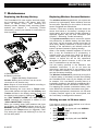
Replacing the Backup Battery........................ 39
Replacing Wireless Sensors Batteries............. 39
Gaining access to 24-hour zones .................. 39
Cleaning the Control Panel ............................ 40
Event Log.......................................................... 40
Reading the Event Log ................................... 40
Exiting the Event Log ...................................... 41
APPENDIX A. GLOSSARY................................ 42
APPENDIX B. HOME FIRE ESCAPE PLANNING
......................................................................... 44
FCC STATEMENT.............................................. 45
1
INTRODUCTION
1. Introduction
Preface
Dear Customer,
Thank you for choosing PowerMax10-G2, a highly
advanced wireless alarm control system produced by
Visonic Ltd.
Also please make sure that you have the name and
telephone number of the monitoring station your
system will report to. If you ever call the monitoring
station to ask questions, you should be able to come
up with your "ACCOUNT NUMBER" used to identify
your alarm system to the monitoring station. Obtain
this information from your installer and write it.
Overview
The PowerMax10-G2 is a wireless alarm control
system that provides protection against burglary, fire
and tampering. In addition, it can be used to monitor
the activity of disabled or elderly people left at home.
Status information is presented visually.
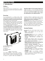
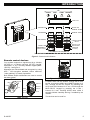
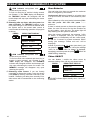
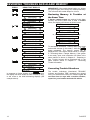
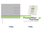
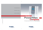
The PowerMax10-G2 is governed by a control panel
(Fig. 1) designed to collect data from various sensors
that are strategically located within and along the
perimeter of the protected site (Figure 2).
In the disarmed state, the system provides you
with visual status information, and initiates an alarm
if smoke is detected or upon disturbance in a 24hour zone (a zone which is active 24-hours a day).
In the armed state, the system will initiate an alarm
upon detection of disturbance in any one of the
armed zones.
A
B
C
D
E
A. INTERNAL SOUNDER
B. INDICATORS
C. DISPLAY
D. CONTROL KEYS
E. KEYPAD
Figure 1. Control Panel
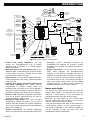
The system identifies a wide range of events alarms, attempts to tamper with sensors and several
types of trouble. Events are automatically reported
via PSTN or optional GSM and Broadband to
2
monitoring stations (in digital form) and to private
telephones (in tones and/or SMS messages). The
person receiving such a message is expected to
investigate the event and act accordingly.
IMPORTANT! All you need to know to secure your
premises can be found in Chapter 2 of this manual.
If you are not familiar with some of the terms used
here, refer to Appendix A at the end of this guide.
Note: This system must be checked by a qualified
technician at least once every three (3) years.
System Features
Your PowerMax10-G2 offers a large number of unique
features:
• Master / User Settings: Two user levels allow
different access types.
• 29 zones: Each protected zone is identified by
number and by name.
• Multiple arming modes: AWAY, HOME, AWAYINSTANT, HOME-INSTANT, LATCHKEY and
BYPASS.
• Liquid crystal display (LCD): Plain-language
status information and prompts are displayed on
the front panel in large, clear letters.
• Real-time clock: The present time is visible on the
display. This feature is also used for the log file by
providing the date and time of each event.
• Various reporting destinations: Events are
reported automatically to monitoring stations,
private telephones of your choice, to a pager and
even by SMS if GSM is installed.
• Selective reporting: Your installer can determine
what type of event will be reported to which
destination.
• Latchkey mode: An automatic “Latchkey”
message is sent to chosen telephones if the
system is disarmed by a “latchkey” user (a junior
family member, for instance).
D-302757
INTRODUCTION
TEL
SMS
EMERGENCY
PENDANT
TRANSMITTERS
DOOR OR
WINDOW
OPEN/CLOSE
DETECTOR
GSM
TELEPHONE GPRS INTERNET
EXCHANGE
LOCAL
COMPUTER
(OPTION)
INTERNET
ROUTER
UNIVERSAL
PERIMETER
PROTECTION
DETECTOR
WIRELESS
DETECTORS
(UP TO 28 UNITS)
INSTALLED IN
THE PROTECTED
PREMISES
CENTRAL
MONITORING
STATION
WIRELESS
SIREN OR
EXTERNAL
SIREN
(future option)
PAGER COMPANY
COMPUTER
USER
COMPUTER
PAGER
4 PRIVATE
TELEPHONES
SMOKE
DETECTOR
TEL. LINE
TEMPERATURE
DETECTOR
PUBLIC
TELEPHONE
EXCHANGE
MOTION
DETECTOR
FLOOD
DETECTOR
CO / GAS
DETECTOR
AWAY
HARD WIRED
DETECTOR
KEYFOB
2-WAY KEYFOB
TRANSMITTER TRANSMITTER
A COMBINATION OF UP TO 8
UP TO 2
UP TO 8
KEYPAD
WIRELESS
DEVICES
REMOTE
COMMANDERS
CENTRAL MONITORING
STATIONS
Figure 2. Typical System Configuration
• Access from remote telephones: You may
access the PowerMax10-G2 from a remote
telephone and Arm/Disarm it or receive system
status information.
• Numerical keys serve as function keys: In the
disarmed state, numerical keys are used to control
various system functions. A simple icon on each
key identifies the task of that key.
• Data retrieval: You can obtain status information,
trouble information and review memorized alarm
events visually.
• Looking after elderly, physically handicapped
and infirm individuals: The system can be
programmed to monitor activity within the
protected area and send out an alert message if
the person under surveillance remains still for a
predefined period of time (as set by your installer).
• Distress calls: Miniature pushbutton transmitters
dealt out to specific individuals may be used for
sending emergency calls for help.
• Disarming under duress: If a user is forcibly
compelled to disarm the system, he can use a
special code that disarms the system apparently
as usual, but sends a silent alarm to the monitoring
station (see chapter 4).
• System supervision: All wireless peripherals
within the protected site send periodic supervision
D-302757
messages. If such a message is overdue, the
PowerMax10-G2 displays an ‘inactivity’ trouble
message. Your installer can disable this feature if
so desired.
• Battery supervision: You do not have to worry
about ‘dead’ batteries. The PowerMax10-G2
displays a ‘Low Battery’ message whenever a
battery in a wireless sensor is found to be near the
end of its useful life. When the battery voltage in
the wireless siren is low, a low battery message is
sent to the alarm system. After the low voltage
message delivery, at least 2 siren alarms are
possible before the siren is totally inactive.
Users and Codes
You will need a 4-digit security code to master the
system (code 0000 is not allowed), and you can
authorize 7 other persons to use the system by
providing them with their own security codes.
Moreover, you can obtain up to 8 multi-function
key-ring transmitters that will allow you and other
users to easily control major functions.
If the user has changed the state of the system from
a high security mode to a lower security mode i.e.
from ARM to DISARM, or from ARM to HOME, he
will be prompted to enter the user code thus
bypassing the QUICK ARM option.
3
INTRODUCTION
Internal Sounder
Alarm Type
Burglar / 24
hour/ Panic
Fire
Test*
Graphic Representation of Signal
–––––––––––––––––––––––––––––––
Verbal Description of Signal
ON continuously
– – – – – – – – – – – – .................
–– (both external and internal sirens)
ON - ON - ON - pause - ON - ON - ON - pause.....
ON for 2 seconds (once)
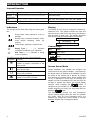
Indicators
Display
The sounds you will hear while using the control panel
are:
The display is in the form of a single line, backlit 16character LCD. The display includes the time and
date and is also used for the log file by providing the
date and time of each event. The display alternates
with the time and the system status, for example:
READY
HH:MM
(alternating)
READY MEMORY
Single beep, heard whenever a key is
pressed
Double beep, indicates automatic return
to the normal operating mode (by
timeout).
Three beeps, indicates a trouble event
☺
Happy Tune (- - - –––), indicates
successful completion of an operation.
Sad Tune (–––––), indicates a wrong
move or rejection
The LEDs you will see on your control panel are:
Inidcation
Function
Power (Green): Indicates that your
system is properly connected to the
power outlet.
Arm (Red): Lights when the system is
in the armed state.
Chime (Green): Chime zones will
chime when disturbed
Trouble (Orange): Lights when the
system is in a state of trouble.
Control Keys
Key
Task
Advance from item to item within a
given menu.
Move one step back within a given
menu
Review status messages one by one
I OK and also select a displayed option.
Screen Saver Mode
During installation your installer can configure the
screen saver for the system's display. The purpose of
the Screen Saver (if enabled by the installer) is to hide
the status of the system and to prevent an intruder
from knowing the system status. When enabled and
no key is pressed for more than 30 seconds, the
display will read “PowerMax10-G2” and the LEDs do
not light or indicate any status. The normal display
button. If
resumes when pressing the
configured by the installer for additional security, the
system will ask you to enter your user code after you
press the
button
The pressed key (except Fire and Emergency)
causes normal display return but does not perform
any action. With Fire and Emergency keys, the
pressed key causes the normal display to resume
and also initiates Fire or Emergency alarm.
4
D-302757
INTRODUCTION
INDICATORS
POWER
ARM
CHIME
TROUBLE
DISPLAY
NEXT
MOVE BACK
SHOW / OK
ARMING “HOME”
DISARMING
ARMING “AWAY”
CHIME ON/OFF
CANCEL ENTRY
DELAY
PA RT ITIO N
SELECTION*
EVENT LOG
EMERGENCY
(hold for 2 sec.)
FIRE (hold
for 2 sec.)
PRESS BOTH FOR PANIC ALARM
* Not included in all models
Figure 3. Controls and Indicators
Remote control devices
Your system responds to signals sent by a 4-button
(KF-234) or a 6-button two-way (KF-237) ‘keyfob’
transmitter, or by a two-way wireless keypad (MKP150/151) - see figure 4.
Messages are authenticated and encrypted, by using
AES - 128 encryption standard, hence malicious
“code grabbing” is virtually impossible.
Both wireless keyfob transmitters are used to control
the alarm system.
KF-237
KF-234
DISARM
AWAY
DISPLAY
HOME
DISARM
AUX
AWAY
HOME
AUX A
MKP-150 /151
D-302757
STATUS
AUX B
AWAY
Figure 4. Keyfob Transmitters and Keypad
A PANIC alarm can be initiated: through the KF-234
keyfob, by pressing AWAY and HOME together for 2
sec.; through the KF-237 keyfob, by pressing the
AUX1 and AUX2 buttons for 2 sec.; and through the
MKP-150/151 keypad by pressing the # and *
buttons for 2 sec. Pressing AWAY twice within 2
seconds initiates Latchkey arming, if enabled by the
installer.
The devices can be used for:
5
INTRODUCTION
A.
Arming the system in the INSTANT mode:
Pressing the AUX button immediately after
arming, during exit delay, causes the system to
be armed without an entry delay. This means
that entering the protected premises via any
zone will trigger an immediate alarm. You and
other holders of keyfob transmitters will have no
problem, because you can disarm the system
before entering by pressing the DISARM ( )
button on your transmitter before entry.
B. Skip exit delay: Pressing the AUX button will
immediately cause the system to arm “instant”.
Disarming by a keyfob whose battery voltage is
low (if enabled by the installer)
If you try to disarm the system with a keyfob whose
battery voltage is low, a protest beep will be heard for
15 seconds. During this period you should press again
the disarm button of the keyfob or control panel (for the
control panel, user code is required) to disarm the
system. If you perform this action during the 15 seconds
period, the Low Bat acknowledge message will be
stored in the event log.
If the disarm button is not pressed again during the
15 seconds period, perform either of the following
actions when you want to rearm the system:
A. Press AWAY twice to arm the system, otherwise the
system will not be armed and an acknowledgement
(from the user that he knows about the Low Bat) will
not be stored in the event log.
B. Press AWAY and then press disarm button, to
acknowledge, otherwise the acknowledgement
will not be stored in the event log.
6
The sounds you will hear while using the control panel
are:
Single beep, heard whenever a key is
pressed
Double beep, indicates automatic return
to the normal operating mode (by
timeout).
Three beeps, indicates a trouble event
☺
Happy Tune (- - - –––), indicates
successful completion of an operation.
Sad Tune (–––––), indicates a wrong
move or rejection
D-302757
OPERATING THE POWERMAX10-G2 SYSTEM
2. Operating the PowerMax10-G2 System
Security-Related Pushbuttons
Key
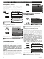
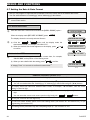
Arming ‘HOME'
If all perimeter zones are READY, and quick arming
is allowed, proceed as shown:
Function
Arming when nobody is at home
Arming when people remain at home
Canceling the entry delay upon arming
(‘AWAY-INSTANT’ or ‘HOME-INSTANT’)
Disarming the system and stopping
alarms
RESULTANT DISPLAY
PRESS
ARMING HOME
Move to interior zone
ARM indicator flashes during the armed state.
Before arming, make sure that READY is displayed.
This means that all zones are secured and you may
arm the system any way you choose.
When the system is not ready for arming (at least
one zone is open) the display is NOT READY TRBL
(trouble), NOT READY MEM (memory), NOT
READY MSG (message) or NOT READY BYPASS.
If the system is not ready for arming, click
to review the numbers and names of all open zones,
one by one.
It is highly recommended to fix the open zone(s), thus
restoring the system to the state of “ready to arm”. If you
do not know how to do this, consult your installer.
IMPORTANT! All arming procedures below are
based on the assumption that quick arming has been
enabled by the installer. If quick arming is disabled,
the PowerMax10-G2 will prompt you to enter your
security code before arming.
Switching from ‘HOME’ to ‘AWAY’
Do not disarm the system - just press
. The
response will be the same as in ARMING AWAY above.
Vacate the premises before the exit delay expires.
Switching from ‘AWAY’ to ‘HOME’
Do not disarm the system - simply press
.
Since this operation reduces the security level, the
PowerMax10-G2 will ask you to key in your master
user code or user code, thus making sure that you
are an authorized user.
PRESS
If the system is READY, proceed as shown:
RESULTANT DISPLAY
ARMING AWAY
[Enter code]
Move to interior zone
PRESS
(Exit delay)
ARMING HOME
↓ (Exit delay) ↓
ARM HOME HH:MM
RESULTANT DISPLAY
ENTER CODE
↓
AWAY
ARM indicator lights steadily during the armed
state.
____
ARM indicator flashes during the armed state.
If an alarm occurred while the system was armed in
the AWAY mode, the display will respond differently:
PLEASE EXIT NOW
↓
RESULTANT DISPLAY
ENTER CODE
Arming ‘AWAY’
Vacate the premises
↓
(Exit delay)
AWAY HH:MM
Preparing to Arm
PRESS
↓
[Enter code]
Move to interior zone
____
ARMING HOME
↓ (Exit delay) ↓
HOME HH:MM
(alternating)
ARM HOME MEMORY
ARM indicator flashes during the armed state.
D-302757
7
OPERATING THE POWERMAX10-G2 SYSTEM
PRESS
Arming AWAY ‘Instant’
RESULTANT DISPLAY
ENTER CODE
____
ARMING AWAY
PLEASE EXIT NOW
(to mute the buzzer)
↓ (Exit delay)
AWAY
ARM indicator lights during the armed state.
When NOT READY is displayed, Forced arming
“HOME” is performed as follows:
ARMING INSTANT
(alternating)
PRESS
PLEASE EXIT NOW
↓ (Exit delay) ↓
AWAY
RESULTANT DISPLAY
ENTER CODE
↓ (Exit delay) ↓
(To mute the buzzer) HOME
Go to interior zone
Arming HOME ‘Instant’
If you wish to arm HOME-INSTANT, proceed as follows:
RESULTANT DISPLAY
ENTER CODE
____
ARMING HOME
ARMING HOME
(alternating)
ARM HOME INSTANT
Move to interior zone
↓ (Exit delay) ↓
HOME HH:MM
ARM indicator flashes during the armed state.
Forced Arming AWAY
Forced arming allows you to arm the system even
though one zone or several zones are disturbed, and
the NOT READY message is displayed.
Automatic forced arming only works if the installer
allowed this option while programming your system.
Disturbed zones will be bypassed - they will not be
armed. The protected site will not have maximum
protection.
Note: When forced arming is carried out, the buzzer
“protests” by emitting a continuous tone during the exit
delay until the last 10 seconds of the delay. You can
silence this signal by pressing the arming button again.
When NOT READY is displayed, Forced arming
“AWAY” is performed as follows:
8
____
ARMING HOME
ARM indicator lights during the armed state.
PRESS
↓
Forced Arming HOME
ARMING AWAY
Vacate the premises
____
ENTER CODE
You may arm AWAY or HOME without an entry
delay - any detection in any zone will trigger an
immediate alarm.
If you wish to arm AWAY-INSTANT, proceed as
follows.
PRESS
RESULTANT DISPLAY
HH:MM
ARM indicator flashes during the armed state.
Arming in the Latchkey Mode
This mode is useful for a parent at work who wants
to be sure that his children have returned from
school and have disarmed the system. Arming in the
“latchkey” mode means that a special “latchkey”
message will be sent out when the system is
disarmed by a “latchkey user”.
Latchkey users are holders of user codes 5 through 8 or
users of Keyfob transmitters 5 through 8. The latchkey
message is considered an alert and not an alarm, and
is therefore sent to the private telephones programmed
by the user as targets for alert messages.
Latchkey arming is possible only when you arm
“AWAY”. To arm in the Latchkey mode, proceed as
follows with the appropriate Keyfob:
PRESS
RESULTANT DISPLAY
ARMING AWAY
ARMING LATCHKEY
(alternating)
(Within 2 seconds)
PLEASE EXIT NOW
Vacate the premises
↓ (Exit delay) ↓
AWAY
Note: Latchkey must be enabled by your installer.
ARM indicator lights during the armed state.
D-302757
OPERATING THE POWERMAX10-G2 SYSTEM
Initiating a Panic Alarm
PRESS
You can generate a panic alarm manually in the
disarmed and armed states alike. The sequence will
be as shown:
PRESS
RESULTANT DISPLAY
PANIC ALARM
READY HH:MM
Note: If you are using a key-ring transmitter, press
both AWAY and HOME buttons (KF-234) or AUX1
and AUX2 (KF-237) simultaneously for 2 seconds.
READY
HH:MM
ARM indicator extinguishes
B. Disarming after alarm, with all zones ready: If
the zone that alarmed in the armed state is back
to normal the disarming operation will progress
as shown:
PRESS
RESULTANT DISPLAY
____
CODE
READY
HH:MM
(alternating)
Initiating Fire Alarm
(This function is disabled in ACPO compliant version).
You can generate a fire alarm in disarmed & armed
states, as follows:
RESULTANT DISPLAY
FIRE
Then, if or when the system
is in the disarmed state:
READY
HH:MM
(alternating)
READY MEMORY
To stop the alarm, press
your valid user code.
and then key in
Initiating Emergency Alarm
You can generate an emergency alarm manually in
the disarmed and armed states, as follows:
PRESS
RESULTANT DISPLAY
EMERGENCY
Then, if or when the system
is in the disarmed state:
READY
HH:MM
(alternating)
READY MEMORY
Disarming and Stopping Alarms
(This function is disabled in ACPO compliant version).
Disarming the system stops the siren before it stops
automatically, irrespective of whether the alarm was
initiated in the armed or the disarmed state.
After disarming, different displays may appear,
depending on the current status of the system:
A. Disarming - no events: After an uneventful
armed term the disarming operation will progress
as shown:
D-302757
____
CODE
and then key in
To stop the alarm, press
your valid user code.
PRESS
RESULTANT DISPLAY
READY MEMORY
ARM indicator extinguishes.
To read the alarm memory, refer to Chapter 3.
The "MEMORY" message will disappear only
upon re-arming the system.
C. Disarming after an alarm, with one zone still
disturbed: If the zone that alarmed in the armed
state is still disturbed the disarming operation will
progress as shown:
RESULTANT DISPLAY
PRESS
CODE
____
NOT READY HH:MM
(alternating)
NOT READY MEMORY
ARM indicator extinguishes
To read the alarm memory, refer to Chapter 3.
The "MEMORY" message will disappear only
when you rearm the system.
If you do not know how to return the disturbed
zone to normal, consult your installer.
D. Disarming with the system in a state of
trouble: If trouble is detected in the armed
state, the TROUBLE indicator on the front panel
will light and the disarming operation will
progress as shown:
RESULTANT DISPLAY
PRESS
CODE
____
READY HH:MM
(alternating)
READY TROUBLE
9
OPERATING THE POWERMAX10-G2 SYSTEM
ARM indicator extinguishes and
sounds once per minute,
To find out what kind of trouble is being sensed,
see Chapter 3. The TRBL display will disappear,
the TROUBLE indicator will extinguish and the
trouble beeps will stop upon eliminating the cause
for trouble.
E. Disarming after an alarm, with the system in a
state of trouble: The TROUBLE indicator on the
front panel will light. If the zone that alarmed while
the system was in the armed state reverts to
normal mode the disarming operation will progress
as shown:
RESULTANT DISPLAY
PRESS
CODE
____
READY HH:MM
(alternating)
READY TRBL
(alternating)
READY MEMORY
ARM indicator extinguishes and
sounds once per minute.
To find out which zone alarmed and what kind of
trouble is being sensed, see Chapter 3. The
TRBL display will disappear, the TROUBLE
indicator will extinguish and the trouble beeps will
stop upon eliminating the cause for trouble. The
MEMORY message will disappear only upon
rearming the system.
F. Disarming under Duress. If you are forcibly
compelled to disarm the system, enter the duress
code (2580 by default) or another code set by the
installer. Disarming will take place normally but a
silent alarm will be transmitted to the monitoring
station.
10
Siren Behavior
The total siren time does not exceed the maximum
time as configured by the installer.
Continuously ON when initiated by a burglar zone
or a 24-hour zone, and when a user initiates a “panic
alarm”.
When initiated by a fire zone (smoke is detected) ON ON - ON - pause - ON - ON - ON - pause - ........
and so on.
If there is nobody around to disarm the system upon
alarm, the siren will sound for the time duration set
by the installer - then will stop. The strobe light will
keep flashing until the system is disarmed.
When the system is disarmed, the message "<OK>
for AWAY" is displayed. Now you can press the
I OK button to immediately arm the control panel,
or wait for 3 second for system automatic AWAY
arming (the message "Please exit now" will be
displayed).
Instead of pressing the I OK button (see above), you
can press the
button once / twice (the message
"<OK> for HOME" / "<OK> for disarm" is displayed,
accordingly) and then press the press I OK button for
HOME arming / disarming.
Chime ON/OFF
You can disable / enable the chime zones by
alternate clicking of the <8> key, as shown below:
PRESS
RESULTANT DISPLAY
CHIME ON
CHIME OFF
↓
READY
HH:MM
CHIME indicator lights steadily when “chime on”
is selected.
D-302757
REVIEWING TROUBLES AND ALARM MEMORY
3. Reviewing Troubles and Alarm memory
Alarm & Tamper Memory
The PowerMax10-G2 retains in its memory alarm
and “tamper” events that occurred during the last
arming period.
Note: Alarms enter the memory only after expiry of the
“abort period” (see Appendix A). This means that if you
disarm the system immediately - before the abort period
expires - there will be no memory indication
A. Indication of Alarm & Tamper Condition
When the memory contains at least one event and
the system is in the disarmed state, a flashing MEM
message will be displayed, as exemplified:
EXAMPLE 2: An alarm was triggered because the
garage door - zone No. 12 – was opened and remained
open.
PRESS
RESULTANT DISPLAY
I OK
NOT READY
I OK
Z12 ALARMED
(alternating)
GARAGE DOOR
I OK
READY
HH:MM
(alternating)
READY MEMORY
or, if the system is not ready for arming NOT READY
HH:MM
(alternating)
NOT READY
MEMORY
B. Displaying Alarm & Tamper Information
To review memory content, click
I OK
button.
EXAMPLE 1: An alarm was triggered because the
garage door - zone No. 12 – was opened but then
closed. In addition, the bedroom motion detector - zone
No. 7 - sent a “Tamper” message because its cover had
been removed.
RESULTANT DISPLAY
PRESS
I OK
READY
I OK
Z12 ALARMED
HH:MM
(alternating)
GARAGE DOOR
I OK
Z07 TAMPER-OPEN
(alternating)
BEDROOM
↓
READY HH.MM
I OK
In response to additional clicking of the
button, the display shows details of other events
retained in open tamper (if any), or reverts to its
initial state (see A above).
D-302757
HH:MM
Z12 OPEN
(alternating)
GARAGE DOOR
↓
NOT READY HH:MM
Remember! The memory indication and content are
cleared upon the next arming of the system.
Troubles
A. Indication of Trouble condition
If TRBL flashes in the display, the TROUBLE
indicator illuminates, and 3 beeps are sounded once
per minute, you will have to investigate the system in
order to find out the origin and type of trouble.
B. Displaying Trouble Information
In a state of trouble, a flashing TRBL message is
displayed as shown in the following examples:
READY
HH:MM
(alternating)
READY
TRBL
or, if the system is not ready for arming NOT READY
HH:MM
(alternating)
NOT READY
TRBL
The trouble message will appear after the
synchronization process following power-up. If the
device does not send a message within the first five
minutes, this indicates supervision trouble.
You can review the current troubles one by one, by
I OK button.
clicking the
EXAMPLE: The kitchen device - zone No. 9 - has
been inactive, the living room device - zone No. 15 has reported a low battery, the utility room device zone No. 2 - was not successfully enrolled, the front
door device - zone No. 5 - was not successfully
configured and the garage device - zone No. 11 –
communicates using one way communication only.
However, these troubles do not prevent the system
from being “ready to arm”.
To investigate the source of trouble, proceed as
follows:
11
REVIEWING TROUBLES AND ALARM MEMORY
PRESS
RESULTANT DISPLAY
I OK
READY
I OK
Z09 MISSING
(alternating)
Z09 CONTACT
(alternating)
KITCHEN
HH:MM
I OK
Z15 LOW BATT
(alternating)
LIVING ROOM
(alternating)
READY HH.MM
I OK
Z02 NOT NETWORKD
(alternating)
Z02 CONTACT
(alternating)
UTILITY ROOM
I OK
Z05 NOT UPDATED
(alternating)
Z05 CONTACT
(alternating)
FRONT DOOR
I OK
Z11 BAD COMM
(alternating)
Z11 CONTACT
(alternating)
GARAGE
OK
I
In response to further clicking of the
button,
the display will show details of other troubles (if any),
or will revert to the initial alternating displays (see
example above).
12
IMPORTANT! If the trouble beeps bother you, disarm
the system again (even though it is already disarmed).
This will cancel the trouble beeps for 4 hours.
Reviewing Memory & Troubles at
the Same Time
If alarms / tamper events are retained in the alarm
memory and at the same time a state of trouble
exists, the display will behave as shown below:
READY
HH:MM
(alternating)
READY
MEMORY
(alternating)
READY
TRBL
or, if the system is not ready for arming NOT READY HH:MM
(alternating)
NOT READY MEMORY
(alternating)
NOT READY TRBL
To read status information - memory data, open zones
I OK
and trouble sources (in this order) - click the
button repeatedly. The memory content will be
displayed first, in the same manner shown in Chapter
5 - Reviewing Alarm / Tamper Memory. If the system
is not ready, open zone information will follow in the
same manner as shown in Chapter 2 - Preparing to
Arm. Trouble sources will be displayed last, in the
same manner shown in Chapter 5 - Reviewing
Trouble Information.
Correcting Trouble Situations
The trouble indications (illuminated TROUBLE
indicator and flashing TRBL message) are cleared
once you eliminate the cause for trouble. If you do
not know how to cope with a trouble situation,
report it to your installer and seek his advice.
D-302757
REVIEWING TROUBLES AND ALARM MEMORY
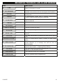
Fault
What it means
1-WAY
The control panel cannot configure or control the device.
Battery consumption increases.
NOT NETWORKED
A device was not installed or not installed correctly, or, cannot
establish communication with the control panel after installation.
MISSING
A device or detector has not reported for some time to the
control panel.
JAMMING
A radio-frequency signal which is blocking communication
channel of sensors and control panel is detected.
LOW BATTERY
The battery in a sensor, keyfob or wireless commander is near the
end of its useful life.
CLEAN ME
GAS TROUBLE
SIREN AC FAILURE
AC FAILURE
The fire detector must be cleaned
Gas detector failure
There is no power to the siren
There is no power to gas sensor
GSM NET FAIL
The GSM communicator is not able to connect to the cellular
network.
RSSI LOW
The GSM communicator has detected that GSM network signal is
weak
AC SUPPLY FAILURE
There is no power and the system is working on backup battery
power
COMM. FAILURE
A message could not be sent to the monitoring station or to a
private telephone (or a message was sent but was not
acknowledged)
CPU LOW BATTERY
The backup battery within the control panel is weak and must be
replaced (see Chapter 7 - Replacing Backup Battery).
CPU TAMPER
The control panel was physically tampered with or its cover was
opened, or it was removed from wall.
FUSE TROUBLE
The PGM fuse is burnt out or overloaded.
LINE FAILURE
There is a problem with the telephone line
D-302757
13
MENUS AND FUNCTIONS
4. Menus and Functions
This chapter explains the programming features of your PowerMax10-G2 system and allows you to tailor the
PowerMax10-G2 system according to your specific needs. The chapter is divided into three sections, as follows:
Part A – Provides you with a general description of available User Setting options.
Part B – Guides you how to enter/exit the User Settings menu and how to select the desired setting options.
Part C – Allows you to execute the selected desired settings.
A The Settings You Need
The installer provides you with a ready-to-use alarm system, but a number of settings will still be needed. The
User Settings menu provides you with essential options that allow you to adapt the system to your specific
needs, to operate it as you desire and to upgrade it when necessary.
Below is a list of the User Settings menu options. A more detailed list is provided in section B.1. Detailed setting
instructions for options 1 to 12 are provided in sections C.1 to C.12.
1. Setting the zone bypass scheme(*)
2. Reviewing the zone bypass scheme(*)
3. Recalling the zone bypass scheme(*)
4. Programming user codes(**)
5. Add / delete keyfob transmitters (**)
6. Setting the time & time format(**)
7. Setting the date & date format(**)
8. Enabling / disabling auto-arming(**)
9. Setting the auto-arming time(**)
10. Programming private phone numbers(**)
11. Enabling / disabling the squawk option(**)
12. Programming the scheduler(**)
*
These menu options are available only if the bypass option was enabled by the installer.
** This option can be accessed only by the master user using the master user code.
Note 1: Although the user settings are your responsibility, you may request your installer to perform them for
you (except for the user codes which you desire to keep secret).
Note 2: Some options may not be available on your PowerMax10-G2 system.
14
D-302757
MENUS AND FUNCTIONS
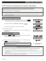
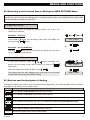
B.1 Entering the User Settings Menu & Selecting a Setting Option
The following procedure describes how to enter and move within the User Settings menu.
Detailed descriptions of the User Setting options are provided at the end of the procedure.
To exit the User Settings menu – see section B.3.
L
1. You can enter the "User Settings" menu only when the system is disarmed.
2. Carefully read the section titled "Additional Information" according to the indicated references 1 etc – see
table at end of this section.
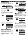
A. To Enter the User Settings Menu
{
a) Make sure the system is disarmed and then press the
button repeatedly until the display reads "USER SETTINGS".1
b) When the display reads [USER SETTINGS], press
I OK
.
READY 00:00
USER SETTINGS
I OK
The screen will now prompt you to enter your user code.
|
Enter your User Code.2
ENTER CODE: XXXX
CODE
The display reads the first Setting option of the User Settings menu
[SET BYPASS].3
SET BYPASS
B. To Select a Setting Option
}
Click the
or
button until the display reads the desired
setting option, for example, "Time & Format".
or
TIME & FORMAT
~
When the desired setting option appears on the display, press the
I OK
I OK
button to enter the setting process.
The remainder of the procedures for the selected setting options 1 to 13
is provided in sections C.1 to C.13.
Continue to the selected
setting option
Additional Information (section B.1)
1
Display shown in disarm state when all zones are secured (00:00 or other digits show present time).
2
a. If you have not already changed your personal code number, use the default setting – 1111.
b. The Master User has access to all User Settings options. All other users have access only to the
Bypass options.
3
The bypass options will be displayed in the User Settings menu only if enabled by the installer. Otherwise,
the first user setting option displayed will be [Private Report].
D-302757
15
MENUS AND FUNCTIONS
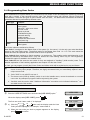
C. User Setting Options Menu
To select the displayed setting option – press the
I OK
button.
Use to set the Zone Bypass Scheme i.e. to bypass (exclude) faulty or unsecured
zones, or to clear a bypassed zone (unbypass). For further details and programming
procedure see section C.1.3
SET ZONE BYPASS
Use to quickly review the Bypass Scheme i.e. which zones are in bypassed state. For
further details and reviewing procedure see section C.2.3
REVIEW BYPASS
Use to Recall the most recent bypassed scheme for use in next arming period. For
further details and recalling procedure see section C.3.3
RECALL BYPASS
Use to program your Master User secret access code and the seven codes of the
other users. For further details and programming procedure see section C.4.
USER CODES
Use to add new Keyfob Transmitters or to delete Keyfob Transmitters when lost. For
further details and programming procedure see section C.5.
KEYFOBS
Use to set the built-in clock to show the correct time and time format. For further
details and programming procedure see section C.6.
TIME & FORMAT
Use to set the built-in calendar date to show the correct date and date format. For
further details and programming procedure see section C.7
DATE & FORMAT
Use to enable or disable the Automatic Daily Arming at predefined times (see Auto-Arm
Time setting). For further details and programming procedure see section C.8.
AUTO-ARM ENABLE
Use to set the predetermined time for the Automatic Daily Arming if enabled (see
Auto-Arm Enable setting). For further details and programming procedure see
section C.9.
Use to program the four private telephone numbers for reporting alarm and other
event messages to private subscribers. For further details and programming
procedure see section C.10
AUTO-ARM TIME
PRIVATE REPORT
Use to enable or disable the squawk sound i.e. arm / disarm feedback indication. For
further details and programming procedure see section C.11.
SQUAWK
Use to set the daily / weekly time schedule for start & stop activation of PGM devices.
For further details and programming procedure see section C.12.
SCHEDULER
Use to exit from the USER SETTING menu back to Main Menu. For further details
see section B.3.
<OK> TO EXIT
Returns to
first option
16
D-302757
MENUS AND FUNCTIONS
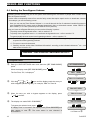
B.2 Returning to the Previous Step or Exiting the USER SETTINGS Menu
During the setting process it is frequently necessary to return to the previous setting step or option (i.e. "to go
one level up") or to exit the User Settings menu. To facilitate these actions, the PowerMax10-G2 system offers
you two alternative methods to choose from.
A. To Move One Level Up
To move one level up during the setting process, use one of the
following two methods:
or
Method #1 – Scrolling:
Click the W or V button until the display reads [<OK> TO LEAVE] and
then press the
I OK
<OK> TO EXIT
button.
I OK
or
Method #2 – Use the HOME key:
Click the
button once or more. Each click will take you one level
up or to the previous setting step.
B. To Exit the USER SETTINGS Menu
To exit "User Settings", press the
button repeatedly (see
above) until the display reads [<OK> TO EXIT] or; press the
button once.
When the display reads [<OK> TO EXIT], press
I OK
.
The system exits the User Settings menu and returns to the normal
disarm state while showing the READY display.
or
<OK> TO EXIT
I OK
READY 12:00
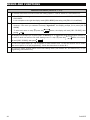
B.3 Buttons used for Navigation & Setting
The keypad's buttons are used for various functions when programming. The following table provides a detailed
description of the function or use of each button.
Button
Navigation / Setting Function
Use to move / scroll forward to the next menu options.
Use to move / scroll back to the previous menu options.
I OK
Use to select a menu option or to confirm a setting or action.
Use to move one level up in the menu or to return to previous programming/setting step.
Use to jump back to the [<OK> TO EXIT] screen to quit programming.
Use to cancel, delete, clear or erase setting, data, etc.
0-9
D-302757
Numerical keypad used to enter numerical data.
17
MENUS AND FUNCTIONS
C.1 Setting the Zone Bypass Scheme
Bypassing permits arming only part of the system while allowing free movement of people within certain zones
when the system is armed.
It is also used to temporarily remove from service faulty zones that require repair work or to deactivate a sensor
if, for example, you are decorating a room.
♦ Here you can set the Zone Bypass Scheme i.e. to scroll through the list of registered (enrolled) sensors to
your PowerMax10-G2 system and to Bypass (deactivate) faulty or disturbed sensors (either READY or
NOT-READY) or to Clear (reactivate) BYPASSED zones (sensors).
Once you have set a Bypass Scheme you can use the following 3 options:
>
To quickly review the bypassed zones – refer to section C.2.
>
To quickly clear a bypassed zone i.e. to reactivate the bypassed zone – refer to section C.2.
>
To repeat (recall) the most recent zone bypassing scheme – refer to section C.3.
L
1. Zones will be bypassed throughout one disarm-arm period only. Disarming the system after arming will
suspend the entire bypassing scheme.
2. Fire zones cannot be bypassed.
3. Carefully read the section titled "Additional Information" according to the indicated references
1
etc – see
table at end of section C.3.
REMEMBER – ZONE BYPASSING COMPROMISES SECURITY!
A. To Bypass a Zone
{
Enter the USER SETTINGS menu and select the [SET ZONE BYPASS]
option.1
When the display reads [SET ZONE BYPASS] press
I OK
SET ZONE BYPASS
I OK
.
The first Zone, Z01, is displayed.2
Z01:
READY
Z01: Living Room
|
or
button until the display reads the zone you
Click the
wish to bypass (or clear bypass), for example, "Z04" for Zone 04.
or
Z04: NOT READY
}
When the zone you wish to bypass appears on the display, press
I OK
Z04: Kitchen
to confirm.
I OK
~
3
The display now reads [<OK> TO BYPASS].
To bypass the selected zone press
18
I OK
<OK> TO BYPASS
I OK
.
A "Happy Tune" ☺ sounds. The display reads [Zone BYPASSED] and
Zone BYPASSED
then returns to step
BYPASSED.6
☺ Return to |
|.
The zone status is now changed to
D-302757
MENUS AND FUNCTIONS
B. To Clear a Bypassed Zone
Repeat steps { to ~ above.
When the zone you wish to clear bypass appears on the display (for
Z04: BYPASSED
example, "Z04"), press
I OK
Z04: Kitchen
to confirm.
I OK
3
The display now reads [<#> TO CLEAR].
To clear the bypassed zone press the
<#> TO CLEAR
button.
A "Happy Tune" ☺ sounds. The display reads [Bypass CLEARED] and
then returns to step |. The zone status is now changed to READY or
NOT READY according to the zone status.6
Bypass CLEARED
☺ Return to |
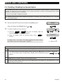
C.2 Reviewing the Zone Bypass Scheme
♦ Here you can quickly review the Bypass Scheme i.e. the zones that are set to be bypassed during the next
arming session.
{
Enter the USER SETTINGS menu and select the [REVIEW BYPASS]
option.1
When the display reads [REVIEW BYPASS] press
I OK
.
The first bypassed zone is displayed, for example, "Z04".
|
REVIEW BYPASS
I OK
Z04: BYPASSED
or
buttons repeatedly to review all bypassed
Click the
zones in ascending numerical order. When done, the display returns to
the User Settings menu (step {).7
Z04: Kitchen
C.3 Recalling the Zone Bypass Scheme
♦ Use this option to repeat (recall) the most recent Bypassed Scheme for use during the next arming session.
{
|
Enter the USER SETTINGS menu and select the [RECALL BYPASS]
option.1
When the display reads [RECALL BYPASS] press
The display now reads [<OK> TO RECALL].4
To recall the most recent bypass scheme press
I OK
.
D-302757
I OK
<OK> TO RECALL
I OK
.
A "Happy Tune" ☺ sounds. The display reads [Bypass RECALLED] and
then returns to the User Setting menu, step {.6
RECALL BYPASS
I OK
Bypass RECALLED
☺ Return to {
19
MENUS AND FUNCTIONS
Additional Information (section C.1 – C.3)
1
For detailed instructions on how to select the Setting Options – refer to section B.1 and section B.2.
2
a. The STATUS to the right of the zone number indicates whether the zone is READY, NOT-READY or
BYPASSED.
b. In the example on the right the display reads [Z01: READY] alternating with [Z01: Living Room].
3
a. If the zone you selected is "not bypassed", the display prompts you to press [<OK> TO BYPASS].
However, if the zone you selected is already "bypassed", the display prompts you to press [<#> TO
CLEAR].
b. To abort and return to step
press
4
| press the
button, the display will read [<OK> TO SKIP], then
I OK
The display now prompts you to press [<OK> TO RECALL] i.e. to repeat the most recent bypass scheme. If
you wish to abort and return to the User Setting menu i.e. step
will read [<OK> TO SKIP], then press
I OK
{ press the
button, the display
.
5
You can now repeat steps | - ~ to bypass or clear another zone. To end this session and to select
other menu options or to quit programming - follow the instructions in section B.3.
6
You can now select another option in the User Setting menu (see section B.1 and section B.2), or quit
programming (see section B.3).
20
D-302757
MENUS AND FUNCTIONS
C.4 Programming User Codes
The PowerMax10-G2 system allows you to authorize up to 8 people to arm and disarm the system by providing
each with a unique 4 digit personal security code, and assigning them with different security levels and
functionalities. There are two types of users: Master User and User, The table below summarizes the different
operations that can be performed by different users:
User type
Function
Master User Arm/disarm
Zone bypass
Authorize 7 other user codes
Set user codes
Report to private
Enroll/delete keyfob
Automatic arming
Enable squawk
Set date and time format
Read event log
Arm/disarm
User
Zone bypass
The 8 user codes are assigned as follows:
User Code 1 is assigned to the Master User of the system (i.e. the owner). It is the only user code that allows
access to the User Setting menu. The default setting of the Master User code 1 is 1111. This code cannot be
erased and must be replaced with a secret code as soon as possible.
User Codes 2-4 are assigned to family members, co-workers etc. They enable arming and disarming of the
system as defined by the Master User. They can access the "User Setting" menu only for "zone bypassing"
provided this option is enabled in the Installer menu.
User Codes 5-8 are the same as user codes 2-4 but are assigned to "Latchkey" (child monitor) users. For a
detailed explanation of the Latchkey application see Chapter 4 in this User Guide.
♦ Here you can program (or edit) the 8 User Codes and define which will be authorized to arm and disarm.
L
1. The default setting 1111 of Master User Code 1 is the same for all PowerMax10-G2 systems and is
known to many other people. Therefore, we highly recommend that you immediately replace it with a
unique secret code.
2. Code "0000" is not valid! Do not use it.
3. The duress code (2580 by default), which is set in the installer menu, cannot be selected as a normal
user code. Any attempt to program it will be rejected by the system.
4. Carefully read the section titled "Additional Information" according to the indicated references
see table at end of this section.
1
etc –
A. To Program a User Code
{
Enter the USER SETTINGS menu and select the [USER CODES] option.1
When the display reads [USER CODES] press
I OK
.
The first user code "user code 1" is displayed.2
|
or
button until the display reads the User
a) Click the
Code you wish to program, for example, "user code 4".
b) When the user code you wish to program appears on the display,
press
D-302757
I OK
USER CODES
I OK
user code 1
or
user code 4
to confirm.
21
MENUS AND FUNCTIONS
I OK
}
a) To program or edit the code, use the numerical keypad to enter the 4
digit code (e.g. 5327) at the position of the blinking cursor.3 4
b) When done, press
I OK
user code 4
I OK
to confirm.
A "Happy Tune" ☺ sounds. The display confirms the saved code.
The display returns to step
( ).5 6
327
user code 4 5327
| showing "User 4 Code" as programmed
☺ Return to |
Additional Information (section C.5)
1
For detailed instructions How to select the Setting Options – refer to section B.1 and section B.2.
2
a. The display shows the 1st User Code (Master User) in the list of 8 User Codes. If you have not yet
changed the default code 1111, we recommend that you change it now.
b. The box on the right indicates whether the location is already programmed ( ) or if the location is free
( ).
3
a. The display shows the user code currently programmed in this location (e.g. 5327).
b. The cursor blinks on the first digit of the code.
c. If the location is free the display will be blank ( - - - - ).
4
You can move the cursor to the next or previous digit using the (
/
) buttons. Pressing the
button erases the digit of the cursor + all digits right of the cursor.
5
The new code is now displayed without the cursor.
6
You can now repeat steps | - to program or edit another user code. To end this session and to
select other menu options or to quit programming – follow the instructions in section B.3.
22
D-302757
MENUS AND FUNCTIONS
C.5 Add / Delete Keyfob Transmitters
Each of the 8 PowerMax10-G2 users may be provided with a portable keyfob transmitter to exercise better,
quicker and safer arming/disarming and other control functions. Each keyfob should be assigned with a serial
No. (1-8) that corresponds to user No. (1-8) and enrolled into the PowerMax10-G2 system.
♦ Here you can add (enroll) the 8 Keyfob transmitters.
L
1. Before anything else, gather up all keyfob units you intend to enroll and make sure they all have
batteries installed and that they are active (the LED blinks upon pressing any of the buttons).
2. Carefully read the section titled "Additional Information" according to the indicated references1 etc – see
table at end of this section.
A. To Add (Enroll) a Keyfob
{
Enter the USER SETTINGS menu and select the [KEYFOBS] option.1
|
When the display reads [ADD/DEL KEYFOBS] press
I OK
.
The display will read [ADD NEW KEYFOB].3
}
~
Press
I OK
I OK
I OK
ADD NEW KEYFOB
. You are now instructed to enroll the keyfob.2
Press the AUX button on the selected keyfob until the orange LED
begins to blink and then release it. Press the AUX button again until the
LED lights and then release it.
-orEnter the 7-digit number that appears on the keyfob sticker and then
press
KEYFOBS
ENROLL NOW or
ENTER ID No
.
The display reads [DEVICE ENROLLED] (or [ID accepted] if the keyfob
was enrolled manually by entering the ID number), a "Happy Tune" ☺
sounds and the display will then change to [K01:Keyfob].
DEVICE ENROLLED
☺
K01:Keyfob
B. To Delete a Keyfob
{
|
Repeat step { above.
Click the
press
button. When the display reads [DELETE KEYFOB]
I OK
.
I OK
2
The display will read [K01:Keyfob].
K01:Keyfob
}
Click the
or
button until the display reads the Keyfob
No. you wish to delete, for example, " K06:Keyfob ".
~
When the keyfob you wish to delete appears on the display, press
I OK .4
or
K06:Keyfob
I OK
5
The display now reads [<OFF> TO DELETE].
D-302757
DELETE KEYFOB
<OFF> TO DELETE
23
MENUS AND FUNCTIONS
To delete the keyfob press the
key.
A "Happy Tune" ☺ sounds and the display reads [DELETE KEYFOB].
DELETE KEYFOB
☺
Additional Information (section C.6)
1
For detailed instructions on how to select the Setting Options – refer to section B.1 and section B.2.
2
The display shows the 1st Keyfob (Keyfob No.1) of the 8 keyfobs.
3
To abort enrollment press the
To Delete a keyfob, make sure that a keyfob is enrolled in that location.
5
a. If a keyfob is enrolled ( ) the display prompts you to press [<OFF> TO DELETE].
b. To abort press the
24
button.
4
button.
D-302757
MENUS AND FUNCTIONS
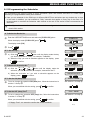
C.6 Setting the Time & Time Format
♦ Here you can program or adjust the built-in-clock to show the correct time in the desired time format.
♦ You can select between a 24 hour and a 12 hour (AM/PM) time format.
L
Carefully read the section titled "Additional Information" according to the indicated references1 etc – see table
at end of this section.
A. To Set the Time Format
{
Enter the USER SETTINGS menu and select the [TIME & FORMAT] option.1
When the display reads [SET TIME & FORMAT] press
I OK
TIME & FORMAT
I OK
.
The display shows the currently selected time format.2
|
EU FORMAT-24H
or
or
button until the display reads the
a) Click the
desired time format, for example, "US FORMAT-12H".
b) When the desired time format appears on the display, press
to confirm.
I OK
US FORMAT - 12 H
I OK
83
B. To Set the Time
}
TIME
12:40P
a) Use the numerical keypad to enter the correct time, for example,
"08:55 AM" at the position of the blinking cursor.4 5
button to toggle between AM & PM (if "US FORMAT
b) Use the
- 12 H" was selected).
c) When you are satisfied with the setting, press
I OK
I OK
to confirm.
A "Happy Tune" ☺ sounds to confirm the set time.7 6
US FORMAT-12H
Additional Information (section C.10)
1
For detailed instructions on how to select the Setting Options – refer to section B.1 and section B.2.
2
a. The display shows the currently selected format (indicated by a
symbol), for example, "24 Hrs".
or
b. You can now select either the 12 Hrs or 24 Hrs time format using the
buttons.
3
The display shows the Time and selected Time Format, for example, "12:40 PM", with the cursor blinking
on the first hour digit "0".
4
a. When the cursor blinks on "h", this indicates hour digit and "m", this indicates minute digit.
b. You can move the cursor to the next or previous digit using the
5
6
Use the
or
buttons.
button to toggle between AM and PM formats.
a. The time is displayed without the cursor, for example, "08:55 A".
b. The letter that follows the displayed time indicates one of the following:
"A" = AM; "P" = PM and "none" for 24 Hrs time format.
7
You can now select another option in the User Setting menu (see section B.1 and section B.2), or quit
programming (see section B.3).
8
This setting can be performed only after completing steps { - | of section C.10A.
D-302757
25
MENUS AND FUNCTIONS
C.7 Setting the Date & Date Format
♦ Here you can program or adjust the built-in-calendar to show the correct date in the desired date format.
♦ You can select between a "mm/dd/yyyy" and a "dd/mm/yyyy" date format.
L
Carefully read the section titled "Additional Information" according to the indicated references1 etc – see table
at end of this section.
A. To Set the Date Format
{
Enter the USER SETTINGS menu and select the [DATE & FORMAT] option.1
When the display reads [SET DATE & FORMAT] press
I OK
DATE & FORMAT
I OK
.
The display shows the currently selected format.2
|
DATE MM/DD/YYYY
a) Click the
or
button until the display reads the
desired date format, for example, "DD/MM/YYYY".
b) When the desired date format appears on the display, press
to confirm.
or
DATE DD/MM/YYYY
I OK
I OK
B. To Set the Date
}
3458
Date:d0/12/2007
a) Use the numerical keypad to enter the correct date, for example,
"20.02.2008" at the position of the blinking cursor.
b) When you are satisfied with the setting, press
I OK
I OK
to confirm.
A "Happy Tune" ☺ sounds to confirm the saved date.6 7
DATE DD/MM/YYYY
☺
Additional Information (section C.11)
1
For detailed instructions on how to select the Setting Options – refer to section B.1 and section B.2.
2
The display shows the currently selected format (indicated by a
symbol), for example, "mm/dd/yyyy".
b. You can now select either the "mm/dd/yyyy" or "dd/mm/yyyy" date format using the (▼/▲) buttons.
3
The display shows the Date and selected Date Format, for example, "30.12.2007", with the cursor
blinking on the first digit.
4
a. When the cursor blinks on "m", this indicates month digit, "d" indicates day digit and "y" indicates year
digit.
b. You can move the cursor to the next or previous digit using the
or
buttons.
5
For the year, enter the two last digits only.
6
You can now select another option in the User Setting menu (see section B.1 and section B.2), or quit
programming (see section B.3).
7
This setting can be performed only after completing steps { - | of section C.11A.
26
D-302757
MENUS AND FUNCTIONS
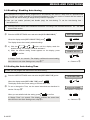
C.8 Enabling / Disabling Auto-Arming
The PowerMax10-G2 system can be programmed to automatically arm itself on a daily basis at a predetermined
time. This feature is useful especially in commercial applications, such as in stores, to ensure that the system is
always armed and without having to assign security codes to employees.
♦ Here you can enable (activate) and disable (stop) the Auto-Arming. To set the Auto-Arming time –
see section C.8.
L
Carefully read the section titled "Additional Information" according to the indicated references1 etc – see table
at end of this section.
{
Enter the USER SETTINGS menu and select the [AUTO-ARM ENABLE].1
When the display reads [AUTO-ARM OPTION] press
I OK
.
`
The display shows the currently selected setting.2
|
I OK
Disable autoarm
or
button until the display reads the
a) Click the
desired setting, for example, "enable autoarm".
b) When the desired setting format appears on the display, press
I OK
AUTO-ARM ENABLE
or
enable autoarm
to confirm.
I OK
A "Happy Tune" ☺ sounds. The display confirms the saved setting,
☺ Return to {
then returns to the User Setting menu, step {.5 3
C.9 Setting the Auto-Arming Time
♦ Here you can program the exact time of the Auto-Arming.
{
Enter the USER SETTINGS menu and select the [AUTO-ARM TIME] option.1
When the display reads [AUTO-ARM TIME] press
I OK
.
AUTO-ARM TIME
I OK
The display shows the current setting of the Auto-Arm Time
|
To set or change the Time, use the same instructions as described in
section C.8 step }.4
When you are satisfied with the setting, press
I OK
to confirm.
arm time 12:00P
See section C.10 step }
I OK
`
A "Happy Tune" ☺ sounds. The display confirms the saved time,
then returns to the User Setting menu, step {.5
D-302757
☺ Return to {
27
MENUS AND FUNCTIONS
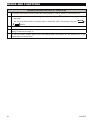
Additional Information (section C.07 - section C.08)
1
For detailed instructions on how to select the Setting Options – refer to section B.1 and section B.2.
2
a. The display shows the current setting format (indicated by a
autoarm".
symbol), for example, "Disable
b. You can now select either to activate (ON) or deactivate (OFF) auto-arming using the
or
buttons.
3
The
4
The display shows the current setting of the Auto-Arm Time, for example, "07:30 PM", with the cursor
blinking on the first hour digit "0".
5
You can now select another option in the User Setting menu (see section B.1 and section B.2), or quit
programming (see section B.3).
28
symbol now appears next to the new selected option.
D-302757
MENUS AND FUNCTIONS
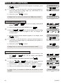
C.10 Programming Private Phone Numbers
The PowerMax10-G2 system allows you to determine which event groups will be reported to private telephone
subscribers. The PowerMax10-G2 system can also be programmed by the installer to report various event
messages such as alarm, arming or trouble, to 4 private telephone subscribers and to 4 SMS telephone
numbers either instead of or in addition to the reports transmitted to the monitoring company. You can
determine the number of times the private telephone number is dialed and whether to use a single
acknowledge signal or an acknowledge signal from each telephone before the current event is considered
reported.
Reported events and the number of reported attempts are programmed in the "Installer Settings" (for further
details see Chapter 6 in this manual).
♦ Here you can program the 1st, 2nd, 3rd, and 4th private telephone numbers for reporting alarm and other event
messages to private subscribers.
♦ Here you can program the 1st, 2nd, 3rd, and 4th SMS telephone numbers for reporting alarm and other event
messages to private subscribers.
L
Carefully read the section titled "Additional Information" according to the indicated references1 etc – see table
at end of this section.
A. To Program Event Group Report
{
a) Enter the USER SETTINGS menu and select the [PRIVATE REPORT]
option.1
b) When the display reads [PRIVATE REPORT] press
The display will read [REPORT TO PRVT].
c) Press
|
}
I OK
I OK
PRIVATE REPORT
I OK
.
REPORT TO PRVT
.
I OK
or
button until the display reads the event
Click the
group you wish to be reported, for example, "alarms".
Select between: "disable report"; "all"; "all (-op/cl)" (all messages except
opened/closed); "all (-alerts)" (all messages except alerts); "alarms";
"alerts"; "op/cl" (opened/closed).
When you are satisfied with the setting, press
I OK
to confirm.6
A "Happy Tune" ☺ sounds to confirm the set event to be reported.
all
or
alarms
I OK
REPORT TO PRVT
☺
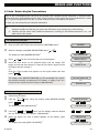
B. To Program SMS Telephone Numbers
{
a) Click the
REPORT TEL#].
or
button until the display reads [SMS
b) When the display reads [SMS REPORT TEL#] press
|
SMS REPORT TEL#
I OK
.
or
button until the display reads the
a) Click the
desired SMS phone number you wish to program or edit, for
example, "4th SMS tel #".2
D-302757
or
I OK
1st SMS tel#
or
29
MENUS AND FUNCTIONS
b) When the desired SMS phone number appears on the display, press
I OK
}
4th SMS tel #
to confirm.
I OK
a) To program or edit the phone No. Use the numerical keypad to
enter the SMS phone number digits (e.g. 8032759333) at the
position of the blinking cursor. 4 5
b) When done, press
I OK
032759641
I OK
to confirm.
A "Happy Tune" ☺ sounds to confirm the set SMS phone number.7
4th SMS tel #
☺
C. To Program a Private Phone
{
a) Click the
REPORT].
or
VOICE REPORT
b) When the display reads [VOICE REPORT] press
|
I OK
.
I OK
st
or
button until the display reads the desired
a) Click the
Telephone No. you wish to program or edit, for example, "4th
private tel#".2
1
b) When the desired private telephone appears on the display, press
4th private tel#
I OK
}
or
button until the display reads [VOICE
private tel#
or
to confirm.
I OK
a) To program or edit the phone No. Use the numerical keypad to
enter the phone number digits (e.g. 8032759333) at the position of
the blinking cursor.4 5
b) When done, press
I OK
032759641
I OK
to confirm.
A "Happy Tune" ☺ sounds to confirm the set phone number.7
4th private tel#
☺
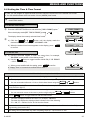
D. To Program the number of redial attempts
{
a) From the Voice Report sub-menu (see the previous section), click
the
or
attempts].
button until the display reads [Redial
b) When the display reads [Redial attempts] press
|
I OK
I OK
to confirm.6
A "Happy Tune" ☺ sounds to confirm the set number of redial
attempts.
30
Redial attempts
.
or
button until the display reads the
a) Click the
desired number of redial attempts, for example, "3 attempts".1
b) Select between: "1 attempt"; "2 attempts"; "3 attempts"; "4 attempts".
c) When you are satisfied with the setting, press
or
I OK
1 attempt
or
3 attempts
I OK
Redial attempts
☺
D-302757
MENUS AND FUNCTIONS
E. To Program the Acknowledge Signal
{
a) From the Voice Report sub-menu, click the
button until the display reads [Tel. acknowledge].
b) When the display reads [Tel. acknowledge] press
|
or
Tel. acknowledge
I OK
.
or
button until the display reads the
a) Click the
desired acknowledge signal, for example, "all ack".3
b) When you are satisfied with the setting, press
I OK
or
to confirm.6
I OK
single ack
or
all ack
I OK
A "Happy Tune" ☺ sounds to confirm the set acknowledge signal.
Tel. acknowledge
☺
Additional Information (section C.4)
1
For detailed instructions on how to select the Setting Options – refer to section B.1 and section B.2.
2
The display shows the 1st of the 4 Private Telephone Numbers / SMS phone numbers.
3
The box on the right indicates whether the location is already programmed ( ).
4
a. The display shows the phone number currently programmed in this location (e.g. 8032759641).
b. The cursor blinks on the first digit of the code.
c. If the location is free the display will be blank ( - - - - ).
5
6
7
You can move the cursor to the next or previous location (digit) using the
The
buttons.
symbol now appears next to the new selected option.
You can now repeat steps
end this session.
D-302757
or
| - } to program or edit another phone number / SMS phone number, or to
31
MENUS AND FUNCTIONS
C.11 Enabling / Disabling the Squawk Option
The PowerMax10-G2 system (and its wireless sirens) can be set to produce a short "Squawk" of audible feedback
to assist you when you use your keyfob to arm (1 beep) and disarm (2 beeps) the PowerMax10-G2 system
(operates in a similar manner to a car alarm).
♦ Here you can enable / disable the Squawk.
L
Carefully read the section titled "Additional Information" according to the indicated references1 etc – see table
at end of this section.
{
Enter the USER SETTINGS menu and select the [SQUAWK] option.1
When the display reads [SQUAWK] press
|
I OK
SQUAWK
I OK
.
To enable / disable or set the Squawk.2
Squawk ON
or
or
button until the display reads the
a) Click the
desired setting, for example, "Squawk ON".
b) When the display reads the desired setting, press
confirm.
I OK
Squawk ON
to
I OK
A "Happy Tune" ☺ sounds. The display confirms the saved setting,
☺ Return to {
then returns to the User Setting menu, step {.4 3
Additional Information (section C.09)
1
For detailed instructions on how to select the Setting Options – refer to section B.1 and section B.2.
2
a. The display shows the currently selected setting (indicated by a
symbol), for example, "Squawk ON".
b. You can now select either to enable (ON) or disable (OFF) the Squawk using the
buttons.
or
3
The
4
You can now select another option in the User Setting menu (see section B.1 and section B.2), or quit
programming (see section B.3).
32
symbol now appears next to the new selected option.
D-302757
MENUS AND FUNCTIONS
C.12 Programming the Scheduler
The PowerMax10-G2 system includes a Home Automation option that enables activation of a PGM output
according to a programmable weekly time schedule.
♦ Here you can schedule for the PGM up to 4 different ON/OFF time activations per any desired day or days
of the week. In addition, you can schedule a "Daily" schedule that applies to every day of the week. It is
recommended to complete the Scheduler table (placed at the end of this section) before programming the
Scheduler.
L
Carefully read the section titled "Additional Information" according to the indicated references1 etc – see table
at end of this section.
A. To Select the Device No.
{
Enter the USER SETTINGS menu and select the [SCHEDULER] option.1
When the display reads [SCHEDULER] press
I OK
.
I OK
The display reads [PGM].
|
Press
I OK
PGM
.
I OK
B. To Set the Day 2
}
Sunday
a) Click the
or
button until the display reads the day
you wish to schedule or "Daily", for example, "Tuesday".
b) When the "day" you wish to schedule appears on the display, press
I OK
to confirm.
3
I OK
to confirm.
D. To Set the ON (Start) Time
I OK
to confirm.
E. To Set the OFF (Stop) Time5
I OK
to confirm.
A "Happy Tune" ☺ sounds to confirm the saved schedule.6
D-302757
operation No 3
See section C.10 step }
I OK
Stop- HH:MM
To set or change the operation OFF (stop) time, follow the instructions
in section C.10 step }.
When you are satisfied with the setting, press
or
Start- HH:MM
To set or change the operation ON (start) time, follow the instructions in
section C.10 step }.
When you are satisfied with the setting, press
`
I OK
4
Tuesday
operation No 1
a) Click the
or
button until the display reads the
activation you wish to schedule, for example, "operation No 3".
b) When the "activation no." you wish to schedule appears on the
display, press
or
I OK
C. To Select the Activation No.
~
SCHEDULER
See section C.10 step }
I OK
☺
33
MENUS AND FUNCTIONS
Additional Information (section C.12)
1
For detailed instructions How to select the Setting Options – refer to section B.1 and section B.2.
2
If you wish to activate the selected device on every day of the week at the same time(s), use the "Daily"
3
or
buttons to select the specific day (Sunday, Monday,
option. Otherwise, use the
Tuesday…etc) you wish to activate the previously selected device. You can later repeat the process for
other days of the week, if desired.
The display shows "operation No 1" which is the first of the 4 ON/OFF time activations you can
schedule for the day selected in the previous step. You can later repeat the process for the other 3
activations on the selected day, if desired.
4
a. The display shows the current ON (start) time setting of the selected activation with the cursor blinking
on the first hour digit.
b. If no time is programmed, the time display will be blank (- -:- - - ).
5
a. The display shows the current OFF (stop) time setting of the selected activation with the cursor
blinking on the first hour digit.
b. If no time is programmed, the time display will be blank (- -:- - - ).
6
To select other menu options or to quit programming, follow the instructions in section B.3.
Device
PGM
34
Device
Description
Day
Wednesday
Operation 1
ON:
OFF:
_ _: _ _
_ _: _ _
Operation 2
ON:
OFF:
_ _: _ _
_ _: _ _
Operation 3
ON:
OFF:
_ _: _ _
_ _: _ _
Operation 4
ON:
OFF:
_ _: _ _
_ _: _ _
D-302757
SPECIAL FUNCTIONS
5. Special Functions
Looking after People Left at Home
Command
Keying Sequence
An important characteristic of the PowerMax10-G2 is
its ability to function in a mode contrary to the usual
behavior of an alarm system. When the system is in
the disarmed state (or even when armed “HOME”
with perimeter protection only), it can keep track of
in-house activity and will report lack of motion in
interior zones if there is no detection of motion within
predetermined time limits.
To use this characteristic, you must ask your installer
to program a specific time limit beyond which lack of
motion will be reported as a “not active” alert.
To make things clear, let us assume that an elderly,
sick or handicapped person is left unattended in a
protected site. This person, disabled or sick as he
may be, will not stay entirely still for hours. It is only
natural that even while being asleep he will turn over
in his bed from time to time. He might also wander
into the kitchen to eat or drink, or to the bathroom for
other necessities. Upon doing so, the bedroom,
bathroom and kitchen motion detectors will detect his
movement.
If, for example, the “lack of motion” time limit is set by
your installer to 6 hours, a virtual 6-hour clock will
carry out a 6-hour “countdown”.
If motion is detected within the 6-hour time frame, the
countdown will restart from the beginning (the virtual
6-hour clock will be “reset”) and no alert message will
be sent out.
If no motion is detected within the 6-hour time frame in
any interior zone, the control panel will send a “notactive” alert message to the monitoring station or to
private telephones designated by the installer.
IMPORTANT! In addition, you may provide the person
confined to interiors with a single-button transmitter for
distress situations, see next paragraph.
A. Control when system calls you
The PowerMax10-G2 allows you to perform
commands when the system connects to your private
telephone.
B. Executable Commands
Quit (end
communication)
[ ] [9] [9] [#]
Command
[ ] [1] [#]
Arming Home
[ ] [2] [#]
[ ] [2] [1] [#]
Arming Away-InstantLatchkey
D-302757
Control
panel
The PowerMax10-G2 can be programmed by the
installer for selective transmission of messages to
private telephone subscribers.
The following siren signal will be sent to private
telephone upon event reporting:
* FIRE: ON - ON - ON - pause.... (- - - - - - ......).
...)
** BURGLAR: ON continuously (
*** EMERGENCY: 2-tone siren; like an ambulance.
The called party must acknowledge the message (as
explained later on), but if he does not respond, the
message will be transmitted repeatedly as many
times as possible within a 45-second time limit.
When the 45 seconds are up, the PowerMax10-G2
will disengage the line and call the next private
telephone number on its list.
The called party can acknowledge the message by
pressing the "2" key on the telephone keypad. As a
result, the PowerMax10-G2 will disengage the line
and consider the event duly reported.
Remote Control by SMS
PowerMax10-G2 system with GSM unit can respond
to SMS commands from any cellular telephone.
The various SMS commands are detailed in the
following table (the detailed SMS message sending
process is described in the cellular telephone user’s
guide). In this table, “<code>” means 4-digit user
code and blank space simply means blank space.
SMS Command List
1
Command
Arm AWAY
2
Arm AWAY instant
Keying Sequence
Disarming
Arming Home-Instant
Arming Away
Arming Away-Instant
Arming Away-Latchkey
Event notifications by Telephone
[ ] [3] [#]
3
4
[ ] [3] [1] [#]
[ ] [4] [#]
[ ] [4] [1] [#]
5
SMS Format
“AWAY <code>”
or
“AW <code>”
“AWAY INST <code>”
or
“AWI <code>”
Arm AWAY Latchkey “LATCHKEY <code>”
or
“LK <code>”
Arm AWAY Latchkey “LATCHKEY INST
instant
<code>”
or
“LKI <code>”
Arm HOME
“HOME <code>”
35
SPECIAL FUNCTIONS
Command
SMS Format
or
“HM <code>”
6
Arm HOME instant
“HOME INST <code>”
or
“HMI <code>”
7
Disarm
“DISARM <code>”
or
“DA <code>”
12 Define custom house “HOUSE NAME <code>
identity (see note)
<house ID>”
or
“HN <code> <house ID>”
13 Query system status “STATUS
<code>”
or
“ST <code>”
Note: House ID includes up to 16 characters, for
example, JOHN'S HOUSE.
36
Event notifications by SMS
The PowerMax10-G2 system can send SMS messages
to a maximum of 4 pre-selected telephone numbers.
Example of the reported SMS messages:
• JOHN’S HOME
**AWAY**
• JOHN’S HOME
**DISARM**
• JOHN’S HOUSE
POWERMAX10-G2: LOW BATTERY
GARAGE: LOW BATTERY
• JOHN’S HOUSE
STATUS MESSAGE 01
(Event list is displayed)
Note: Status messages can be sent only to a calling
telephone whose identity number is not blocked by
the user!
Note: The PowerMax10-G2 may react with a delay
to received SMS messages if a GPRS session is in
progress at the same time.
D-302757
WEEKLY MAINTENANCE
6. Weekly Maintenance
Periodic Test
The components of your security system are designed to be maintenance-free as much as possible.
Nevertheless, it is mandatory to perform a “walk-test” at least once a week and after an alarm event to verify that
all system detectors function properly. Proceed as described in this section and if there is any problem, notify
your installer at once.
The periodic test is an indispensable operation by which you verify that all sirens/devices function properly,
without disturbing the neighbors with loud sirens. The test must be performed at least once a week, and
should include all sirens/devices in all zones.
Before performing the periodic test, all the sirens/devices must be in normal state. Normal state is achieved
when no motion is made for at least 2 minutes.
Note: During the test period, 24-hour zones will not cause an alarm if violated, but a fire zone will function
normally.
L
Carefully read the section titled "Additional Information" according to the indicated references1 etc – see table
at end of this section.
A. To Enter the Periodic Test Menu
{
a) Make sure the system is disarmed and then press the
button repeatedly until the display reads "PERIODIC TEST".1
b) When the display reads "PERIODIC TEST", press
I OK
.
READY 00:00
or
PERIODIC TEST
I OK
2
The screen will now prompt you to enter your user code.
|
Enter your User Code and then press
I OK .3
ENTER CODE: XXXX
CODE
I OK
B. To Periodic Test a Siren
}
The display now reads [SIRENS TEST].4
~
Press
I OK
.
SIRENS TEST
I OK
The display now reads [SIREN N]. This indicates the number of enrolled
sirens in the control panel that have not been tested.
The siren will sound for 3 seconds after which the PowerMax system will
automatically repeat the procedure for the next siren enrolled in the
system.5
SIREN N
When all the sirens have been tested, the display reads [SIREN TESTS
END].
SIREN TESTS END
D-302757
37
WEEKLY MAINTENANCE
C. To Periodic Test a Device
Press
I OK
or
DEVICES TEST
. The display reads [DEVICES TEST].
I OK or
. The display now reads [NOT TESTED NNN].
Press
NNN indicates the number of enrolled devices in the control panel that
have not been tested. This number automatically drops one count for
every tested device.
I OK . The display alternates between the device number, the
Press
device type (e.g. magnetic contact, keyfob, keypad, etc.), and the device
location.6
I OK
NOT ACTIVE NNN
I OK
Z01 NOT ACTIVE
Z01 CONTACT
FRONT DOOR
When the device list has ended, the display reads [<OK> TO LEAVE].
<OK> TO LEAVE
D. To Exit the PERIODIC TEST Menu
To exit "Periodic
[DEVICES TEST].
Press
Press
Test",
press
I OK
,
the
display
reads
, the display reads [<OK> TO END].
I OK
DEVICES TEST
<OK> TO END
I OK
to exit.
Additional Information (Periodic Test)
1
Display shown in disarm state when all zones are secured (00:00 or other digits show present time).
2
If you have not already changed your personal code number, use the default setting – 1111.
3
If the INSTALLER CODE is used to enter the Periodic Test, the devices LED will blink according to the
link quality.
4
To skip the SIRENS TEST, press
5
The Periodic test can be performed on a maximum of three sirens including one internal siren.
6
a. Click
.
to scroll through the list of devices.
b. The device LED blinks continuously 3 seconds after the device is displayed.
38
D-302757
MAINTENANCE
7. Maintenance
Replacing the Backup Battery
Replacing Wireless Sensors Batteries
The PowerMax10-G2 uses regular electrical supply,
but incorporates backup 4.8V battery pack (see
sticker on battery cover). Upon receiving the
following trouble message when reviewing system
troubles (see Chapter 3 - Reviewing Trouble
Information), contact your installer for instructions on
how to proceed:
The wireless sensors supplied with your system are
powered by high-capacity lithium batteries that last
several years, depending on the number of times the
sensor is triggered into transmission.
However, if and when a battery becomes weak, the
sensor itself sends a “low battery” message to the
control panel, and a low battery trouble message is
displayed together with the zone information (see
Chapter 5 - Reviewing Trouble Information).
The keyfob transmitters used to control the system
are powered by an alkaline battery that lasts about
one year if you do not press a button more than 10
times a day. Battery exhaustion is clearly evident by
flashing of the transmitter’s red indicator while the
button is pressed (instead of lighting steadily).
When a low battery indication appears for the first
time, it may be considered as a pre-warning. It
normally gives you ample time (about 30 days) to
obtain a new battery and replace the old one; the
detector or keyfob unit will be fully operational
throughout this period. However, to be on the safe
side, it is advisable not to wait that long.
Use the battery specified in the detector’s own
installation instructions. If you do not have the
instructions, seek the advice of your installer or ask
him to replace the battery in the specific sensor that
sent the low battery message.
The Wireless Commander is powered by a long life 3
V Lithium battery. If the battery is weak when reading
the PowerMax10-G2 event log the display will read,
for example, "C01 Low Battery" (meaning there is a
low battery condition in the wireless commander #01),
and the message "remote commander" will be heard.
For replacing the wireless commander battery, refer
to the MCM-140+ Wireless Commander user guide.
After battery replacement, the detector unit will send
a “battery restored” signal to the control panel, and
the “low battery” message will be cleared.
CPU LOW BATTERY
1
2
1. Battery insertion
2. Battery connection
Figure 10. Battery Replacement
Caution: Battery pack connector can be can be
connected in one direction only.
Note: Dispose of used backup batteries according to
the manufacturer's instructions.
Note: Removing the cover starts a Tamper alarm.
The trouble indicator will light and both Memory and
Trouble will flash in the display window. If you view
I OK key,
the display at this stage by clicking the
the "CPU TAMPER ALARM" and "CPU TAMPER
OPEN" messages are displayed in addition to the
"CPU LOW BATTERY" message.
When you correctly insert fresh batteries and close
the lid tightly, the TROUBLE indicator shuts off. The
MEMORY message continues blinking in the display
(because of the Tamper alarm you triggered). Clear
it by arming the system and disarming it as soon as
the exit delay starts.
Gaining access to 24-hour zones
If you wish to access a sensor defined as a 24-hour
zone without causing an alarm:
•
Click
- the display will read: NORMAL
MODE / WALK TEST.
•
Click
again - the display will read:
USER SETTINGS.
•
Click
I OK - the display will read: ENTER
CODE ___.
D-302757
39
MAINTENANCE
Key your secret 4-digit <User Code> - the buzzer
will play the “happy Tune” (- - - ––––).
You have 4 minutes during which the 24-hour sensor
can be opened and accessed. When the 4 minutes
are up, the system will automatically revert to the
normal mode.
Cleaning the Control Panel
The control panel may occasionally get stained if
touched with greasy fingers, and may accumulate
dust after a long period of use. Clean it only with a
soft cloth or sponge moistened lightly with a mixture
of water and mild detergent, and then wipe it dry.
The use of abrasives of any kind is strictly
forbidden. Also never use solvents such as
kerosene, acetone or thinner. These will certainly
ruin the external finish and damage the
transparency of the top window.
Event Log
All events are memorized in an event log that
contains up to 100 entries. You can access this log,
review the events one by one and draw functional
conclusions.
If the event log fills up completely it continues to
accept new events at the expense of old events - the
oldest event is deleted upon registration of each new
event.
The date and time of occurrence are memorized for
each event. When reading the event log, events are
shown in chronological order - from the newest to the
oldest.
Because of the limited display space, the event
description is shown first, then the date and time.
The two displays are shown alternately several
I OK to move on to an older
times, until you click
event, or until the “no action” 4-minute timeout
restores the system to the normal operating mode.
Access to the event log is provided by clicking the
button and then keying your master user
code.
Should you wish to get an overall view of using
the log, refer to the procedure below.
Reading the Event Log
To read the event log, proceed as follows:
1.
While the system is in the normal operating mode, click the
key.
The PowerMax10-G2 display will change to [ENTER CODE: _].
2.
When the PowerMax10-G2 display reads [ENTER CODE: _], enter
the current master user code.
ENTER CODE: _
The "Happy Tuns" will sound and the PowerMax10-G2 display will
read [LIST OF EVENTS]. (see Important Note!)
LIST OF EVENTS
3.
4.
Click the
I OK
button. The latest event will be shown.
READY 00:00
CODE
I OK
The event is displayed in two parts, for example, "Z13 alarm" then
"09/02/10 3:37 P".
Z13 alarm
I OK
The two displays will be shown alternately until clicking
again to move to the next event or until the event log times out (4
minutes).
09/02/10 3:37 P
I OK button as many times as necessary to read all the
Click the
required data.
I OK
Important Note! Entering an incorrect code 5 times in a row will
initiate a 30-second penalty lockout of the keypad.
Attention: The system will not allow you to erase the event log. Only
the installer is authorized to view and perform this function.
40
D-302757
MAINTENANCE
Exiting the Event Log
1.
2.
or
button from anywhere within the event
Click the
log.
The PowerMax10-G2 display will read [<OK> TO EXIT].
Click the
I OK
button.
The system reverts to the normal operating mode.
D-302757
or
<OK> TO EXIT
I OK
READY 00:00
41
APPENDICES
APPENDIX A. GLOSSARY
This list of terms is arranged in alphabetical order.
Any term indicated by cursive (italic) letters within
the explanatory text can be looked up separately.
Abort Period: When an alarm is initiated, the
internal sounder is activated first for a limited period
of time which is the abort period set by the installer. If
you cause an alarm accidentally, you can disarm the
system within the abort period before the real sirens
start and before the alarm is reported to the remote
responders.
Alarm: There are 2 kinds of alarm:
Loud alarm - both internal and external sirens blare
out constantly and the control panel reports the event
by telephone.
Silent alarm - the sirens remain silent, but the control
panel reports the event by telephone.
A state of alarm is caused by:
• Motion detected by a motion detector
• Change of state detected by a magnetic contact
detector - a closed window or door is opened
• Detection of smoke by a smoke detector
• Tampering with any one of the detectors
• Pressing the two emergency buttons simultaneously
(panic)
Arming: Arming the alarm system is an action that
prepares it to sound an alarm if a zone is “violated”
by motion or by opening a door or window, as the
case may be. The control panel may be armed in
various modes (see AWAY, HOME, INSTANT and
LATCHKEY).
Assigned: Refers to zones.
Associated: Refers to devices.
AWAY: This type of arming is used when the
protected site is vacated entirely. All zones, interior
and perimeter alike, are protected.
Chime Zones: Allow you to keep track of activity in
the protected area while the alarm system is in the
disarmed state. Whenever a chime zone is "opened",
the buzzer beeps twice. The buzzer doesn't beep,
however, upon closing the zone (return to normal).
Residences can use this feature to annunciate
visitors or look after children. Businesses can use it
to signal when customers enter the premises or
when personnel enter restricted areas.
Note: Your installer will never designate a 24-hour
zone or a fire zone as a chime zone, because both
zone types actuate an alarm if disturbed while the
system is in the disarmed state.
Although one zone or more are designated as chime
zones, you can still enable or disable the chime function.
42
Control Panel: The control panel is a cabinet that
incorporates
the
electronic
circuitry
and
microprocessor that control the alarm system. It
collects information from various sensors, processes it
and responds in various ways. It also includes the
user-interface - control keys, numerical keypad,
display, sounder and loudspeaker.
Default Settings: Settings that are applicable to a
specific device group.
Detector: The device (apparatus) that sends an
alarm, that communicates with the control panel (e.g.
Tower 20 AM is a motion detector, MCT-425 is a
smoke detector)
Disarming: The opposite of arming - an action that
restores the control panel to the normal standby
state. In this state, only fire and 24-hour zones will
sound an alarm if violated, but a “panic alarm” may
also be initiated.
Disturbed Zone: A zone in a state of alarm (this
may be caused by an open window or door or by
motion in the field of view of a motion detector). A
disturbed zone is considered “not secured”.
Forced Arming: When any one of the system zones
is disturbed (open), the alarm system cannot be
armed. One way to solve this problem is to find and
eliminate the cause for zone disturbance (closing
doors and windows). Another way to deal with this is
to impose forced arming - automatic de-activation of
zones that are still disturbed upon termination of the
exit delay. Bypassed zones will not be protected
throughout the arming period. Even if restored to
normal (closed), bypassed zones will remain
unprotected until the system is disarmed.
Permission to “force arm” is given or denied by the
installer while programming the system.
HOME: This type of arming is used when people are
present within the protected site. A classic example
is night-time at home, when the family is about to
retire to bed. With HOME arming, perimeter zones
are protected but interior zones are not.
Consequently, motion within interior zones will be
ignored by the control panel, but disturbance of a
perimeter zone will cause an alarm.
Instant: You can arm the system AWAY-INSTANT
or HOME-INSTANT, thereby canceling the entry
delay for all delay zones for the duration of one
arming period.
For example, you may arm the control panel in the
HOME-INSTANT mode and remain within the
protected area. Only perimeter protection is active,
and if you do not expect somebody to drop in while
the system is armed, alarm upon entry via the main
door is an advantage.
D-302757
APPENDICES
To disarm the system without causing an alarm, use
your control keypad (which is normally accessible
without disturbing a perimeter zone) or use a keyfob
transmitter.
Latchkey: The Latchkey mode is a special arming
mode in which designated "latchkey users" will
trigger a "latchkey message" to be sent to a
telephone or a pager when they disarm the system.
For example, if a parent wants to be sure that their
child has returned from school and disarmed the
system. Latchkey arming is only possible when the
system is armed in the AWAY mode.
Magnetic Contact Detector, Wireless: A Magnetcontrolled switch and a wireless PowerCode
transmitter in a shared housing. The detector is
mounted on doors and windows to detect changes in
state (from closed to open and vice versa). Upon
sensing that a door or window is open, the detector
transmits its unique identification code accompanied
by an “alarm” signal and various other status signals
to the control panel. The control panel, if not armed
at that time, will consider the alarm system as “not
ready for arming” until it receives a “restored” signal
from the same detector.
Motion Detector, Wireless: A passive Infrared
motion sensor and a wireless PowerCode transmitter
in a shared housing. Upon sensing motion, the
detector transmits its unique identification code,
accompanied by an alarm signal and various other
status signals to the control panel. After transmission,
it stands by to sense further motion.
Non-Alarm Zone: Your installer can designate a
zone for roles other than alarm. For instance, a
motion detector installed in a dark stairway may be
used to switch on lights automatically when someone
crosses the dark area. Another example is a
miniature wireless transmitter linked to a zone that
controls a gate opening mechanism.
Quick Arming: Arming without a user code. The
control panel does not request your user code when
you press one of the arming buttons. Permission to
use this arming method is given or denied by the
installer while programming the system.
D-302757
Remote Responder: A responder can be either a
professional service provider to which the home or
business owner subscribes (a monitoring station) or a
family relation/friend who agrees to look after the
protected site during absence of its occupants. The
control panel reports events by telephone to both
kinds of responders.
Restore: When a detector reverts from the state of
alarm to the normal standby state, it is said to have
been “restored”.
A motion detector restores automatically after
detection of movement, and becomes ready to detect
again. This kind of “restore” is not reported to the
remote responders.
A magnetic contact detector restores only upon
closure of the protected door or window. This kind of
“restore” is reported to the remote responders.
Sensor: The sensing element: pyroelectric sensor,
photo-diode, microphone, smoke optical sensor etc.
Smoke Detector, Wireless: A regular smoke detector
and a wireless PowerCode transmitter in a shared
housing. Upon detection of smoke, the detector
transmits its unique identification code accompanied by
an alarm signal and various status signals to the control
panel. Since the smoke detector is linked to a special
fire zone, a fire alarm is initiated.
State: AWAY, HOME, AWAY-INSTANT, HOMEINSTANT, LATCHKEY, FORCED, BYPASS.
Status: AC fail, low battery, trouble, etc
User Codes: The PowerMax10-G2 is designed to
obey your commands, provided that they are
preceded by a valid security access code.
Unauthorized people do not know this code, so any
attempt on their part to disarm or defeat the system
is bound to fail. Some operations, however, can be
carried out without a user code as they do not
degrade the security level of the alarm system.
Zone: A zone is an area within the protected site under
supervision of a specific detector. During programming,
the installer allows the control panel to learn the
detector’s identity code and links it to the desired zone.
Since the zone is distinguished by number and name,
the control panel can report the zone status to the user
and register in its memory all the events reported by the
zone detector. Instant and delay zones are “on watch”
only when the control panel is armed, and other (24hour) zones are “on watch” regardless of whether the
system is armed or not.
43
APPENDICES
APPENDIX B. HOME FIRE ESCAPE PLANNING
Fire can spread rapidly through your home, leaving
you a short time to escape safely. Your ability to get
out depends on advance warning from smoke
detectors and advance planning - a home fire escape
plan that everyone in your family is familiar with and
has practiced.
• Pull together everyone in your household and
make an evacuation plan.
• Draw a floor plan of your home, showing two ways
out of each room, including windows. Don’t forget
to mark the location of every smoke detector.
Test all smoke detectors (by a qualified testing
laboratory) periodically, to ensure to ensure their
serviceability. Replace batteries as required.
• Make sure that everyone understands the
escape plan and recognizes the sound of smoke
alarm. Verify that the escape routes are clear and
that doors and windows can be opened easily.
• If windows or doors in your home have security
bars, make sure that the bars have quick-release
mechanisms on the inside, so that they can be
opened immediately in an emergency case.
Quick release mechanisms won’t compromise
your security, but they will increase your chances
of safely escaping a home fire.
• Practice the escape plan at least twice a year,
making sure that everybody is involved - from
kids to grandparents. Allow children to master fire
escape planning and practice before holding a
fire drill at night when they are sleeping. The
objective is to practice, not to frighten, so telling
children there will be a drill before they go to bed
can be as effective as a surprise drill. If children
or others do not readily waken to the sound of
the smoke alarm, or if there are infants or family
members with mobility limitations, make sure that
someone is assigned to assist them in fire drill
and in the event of an emergency.
44
•
Agree on an outside meeting place where
everyone can meet after they’ve escaped.
Remember to get out first, and then call for help.
Never go back inside until the fire department
gives the OK.
• Have everyone memorize the emergency phone
number of the fire department. That way any
member of the household can call from a cellular
phone or a neighbor’s home.
• Be fully prepared for a real fire: when a smoke
alarm sounds, get out immediately and once you
are out, stay bout - leave the firefighting to the
professional!
• If you live in an apartment building, make sure that
you are familiar wit the building evacuation plan. In
case of a fire, use the stairs, never the elevator.
Tell guests or visitors to your home about your
family’s fire escape plan. When visiting other
people’s home, ask about their escape plan. If they
don’t have a plan in place, offer to help them make
one. This is especially important when children are
permitted to attend “sleepovers” at friends' homes.
D-302757
FCC STATEMENT
The 315 MHz model of this sensor complies with Part
15 of the FCC Rules. Operation is subject to the
following two conditions: (1) This sensor may not cause
harmful interference, and (2) this sensor must accept
any interference that may be received, including
interference that may cause undesired operation.
The digital circuit of this sensor has been tested and
found to comply with the limits for a Class B digital
sensor, pursuant to Part 15 of the FCC Rules. These
limits are designed to provide reasonable protection
against
harmful
interference
in
residential
installations. This equipment generates, uses and
can radiate radio frequency energy and, if not
installed and used in accordance with the
instructions, may cause harmful interference to radio
and television reception. However, there is no
guarantee that interference will not occur in a
particular installation. If this sensor does cause such
interference, which can be verified by turning the
sensor off and on, the user is encouraged to
eliminate the interference by one or more of the
following measures:
– Re-orient or re-locate the receiving antenna.
– Increase the distance between the sensor and the
receiver.
– Connect the sensor to an outlet on a circuit different
from the one which supplies power to the receiver.
– Consult the dealer or an experienced radio/TV
technician.
At 315 MHz the product complies with FCC
requirements.
D-302757
NOTE:
THE
MANUFACTURER
IS
NOT
RESPONSIBLE FOR ANY RADIO or TV
INTERFERENCE CAUSED BY UNAUTHORIZED
MODIFICATIONS TO THIS EQUIPMENT. SUCH
MODIFICATIONS COULD VOID THE USER’S
AUTHORITY TO OPERATE THE EQUIPMENT.
WARNING! Owner's instruction notice: "Not to be
removed by anyone except occupant".
If the “PowerMax10-G2” causes harm to the
telephone network, the telephone company will notify
you in advance that temporary discontinuance of
service may be required. If advance notice is not
practical, you will be notified as soon as possible.
Also, you will be advised of your right to file a
complaint with the FCC if it is necessary.
The telephone company may make changes in its
facilities, equipment, operations or procedures that
could affect the operation of the equipment. If this
happens the telephone company will provide
advance notice in order for you to make necessary
modifications to maintain uninterrupted service.
If trouble is experienced with the “PowerMax10-G2”
for repair or warranty information please contact
Visonic Inc USA., 65 West Dudley Town Road,
Bloomfield, CT 06002, phone number: 8 602 430
833, URL: www.visonic.com. If the equipment is
causing harm to the telephone network, the
telephone company may request to disconnect the
equipment until the problem is resolved
45
46
D-302757
D-302757
47
W.E.E.E. Product Recycling Declaration
For information regarding the recycling of this product you must contact the company from which you orignially purchased it. If you are
discarding this product and not returning it for repair then you must ensure that it is returned as identified by your supplier. This product is not
to be thrown away with everyday waste.
Directive 2002/96/EC Waste Electrical and Electronic Equipment.
VISONIC LTD. (ISRAEL):
VISONIC INC. (U.S.A.):
VISONIC LTD. (UK):
VISONIC GMBH (D):
VISONIC IBERICA:
INTERNET:
©VISONIC LTD. 2010
48
P.O.B 22020 TEL-AVIV 61220 ISRAEL. PHONE: (972-3) 645-6789, FAX: (972-3) 645-6788
65 WEST DUDLEY TOWN ROAD, BLOOMFIELD CT. 06002-1376. PHONE: (860) 243-0833, (800) 223-0020
FAX: (860) 242-8094
UNIT 6 MADINGLEY COURT CHIPPENHAM DRIVE KINGSTON MILTON KEYNES MK10 0BZ.
TEL: (0870) 7300800 FAX: (0870) 7300801.
KIRCHFELDSTR. 118, D-42015 DÜSSELDORF, GERMANY, FAX (0211) 60069619
Email: [email protected]
ISLA DE PALMA, 32 NAVE 7, POLÍGONO INDUSTRIAL NORTE, 28700 SAN SEBASTIÁN DE LOS
REYES, (MADRID), ESPAÑA. TEL (34) 91659-3120, FAX (34) 91663-8468. www.visonic-iberica.es
www.visonic.com
POWERMAX10-G2 USER GUIDE
D-302757 Rev 0 (8/10)
D-302757
©Visonic LTD. 2010 PowerMax10
English User Guide D-302757
Designed by Linor Ankri
lly supervised wireless alarm control system Fully supervised wireless alarm control
stem Fully supervised wireless alarm control system Fully supervised wireless alarm
ntrol system Fully supervised wireless alarm control system Fully supervised wireless
arm control system Fully supervised wireless alarm control system Fully supervised
reless alarm control system Fully supervised wireless alarm control system Fully
pervised wireless alarm control system Fully supervised wireless alarm control system
lly supervised wireless alarm control system Fully supervised wireless alarm control
stem Fully supervised wireless alarm control system Fully supervised wireless alarm
ntrol system Fully supervised wireless alarm control system Fully supervised wireless
arm control system Fully supervised wireless alarm control system Fully supervised
reless alarm control system Fully supervised wireless alarm control system Fully
pervised wireless alarm control system Fully supervised wireless alarm control system
lly supervised wireless alarm control system Fully supervised wireless alarm control
www.visonic.com
User Guide
PowerMax10
Fully supervised wireless alarm control system