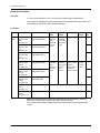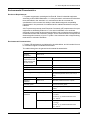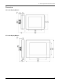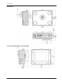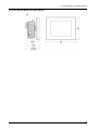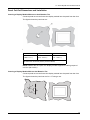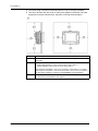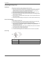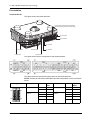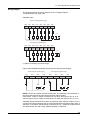
1
/77070 +DUGZDUH0DQXDO The information provided in this documentation contains general descriptions and/or technical characteristics of the performance of the products contained herein. This documentation is not intended as a substitute for and is not to be used for determining suitability or reliability of these products for specific user applications. It is the duty of any such user or integrator to perform the appropriate and complete risk analysis, evaluation and testing of the products with respect to the relevant specific application or use thereof. Neither Pro-face nor any of its affiliates or subsidiaries shall be responsible or liable for misuse of the information that is contained herein. If you have any suggestions for improvements or amendments or have found errors in this publication, please notify us. No part of this document may be reproduced in any form or by any means, electronic or mechanical, including photocopying, without express written permission of Proface. All pertinent state, regional, and local safety regulations must be observed when installing and using this product. For reasons of safety and to help ensure compliance with documented system data, only the manufacturer should perform repairs to components. When devices are used for applications with technical safety requirements, the relevant instructions must be followed. Failure to use Pro-face software or approved software with our hardware products may result in injury, harm, or improper operating results. Failure to observe this information can result in injury or equipment damage. Copyright © 2013.05 Digital Electronics Corporation. All Rights Reserved. 2 LT-4201TM/4301TM Hardware Manual Table of Contents Safety Information . . . . . . . . . . . . . . . . . . . . . . . . . . . . . . About the Book . . . . . . . . . . . . . . . . . . . . . . . . . . . . . . . . . Part I LT System . . . . . . . . . . . . . . . . . . . . . . . . . . . . . . . . . . Chapter 1 LT General Overview . . . . . . . . . . . . . . . . . . . . . . . . . . . . Package Contents . . . . . . . . . . . . . . . . . . . . . . . . . . . . . . . . . . . . . . . . . . . Parts Identification and Functions . . . . . . . . . . . . . . . . . . . . . . . . . . . . . . . System Architecture . . . . . . . . . . . . . . . . . . . . . . . . . . . . . . . . . . . . . . . . . Certifications and Standards . . . . . . . . . . . . . . . . . . . . . . . . . . . . . . . . . . . Devices Overview . . . . . . . . . . . . . . . . . . . . . . . . . . . . . . . . . . . . . . . . . . . Chapter 2 LT System General Rules for Implementing . . . . . . . . . Introduction . . . . . . . . . . . . . . . . . . . . . . . . . . . . . . . . . . . . . . . . . . . . . . . . Installation Requirements . . . . . . . . . . . . . . . . . . . . . . . . . . . . . . . . . . . . . Environmental Characteristics. . . . . . . . . . . . . . . . . . . . . . . . . . . . . . . . . . Wiring Rules and Recommendations . . . . . . . . . . . . . . . . . . . . . . . . . . . . Wiring to the DIO Terminal Block . . . . . . . . . . . . . . . . . . . . . . . . . . . . . . . Grounding the System. . . . . . . . . . . . . . . . . . . . . . . . . . . . . . . . . . . . . . . . Chapter 3 LT Description. . . . . . . . . . . . . . . . . . . . . . . . . . . . . . . . . . 3.1 Rear Module Features. . . . . . . . . . . . . . . . . . . . . . . . . . . . . . . . . . . . . . . . Clock . . . . . . . . . . . . . . . . . . . . . . . . . . . . . . . . . . . . . . . . . . . . . . . . . . . . . 3.2 I/O Management . . . . . . . . . . . . . . . . . . . . . . . . . . . . . . . . . . . . . . . . . . . . Input Management . . . . . . . . . . . . . . . . . . . . . . . . . . . . . . . . . . . . . . . . . . Output Management . . . . . . . . . . . . . . . . . . . . . . . . . . . . . . . . . . . . . . . . . Chapter 4 Device Connectivity . . . . . . . . . . . . . . . . . . . . . . . . . . . . . System Design . . . . . . . . . . . . . . . . . . . . . . . . . . . . . . . . . . . . . . . . . . . . . Interface Accessories . . . . . . . . . . . . . . . . . . . . . . . . . . . . . . . . . . . . . . . . Chapter 5 LT Installation . . . . . . . . . . . . . . . . . . . . . . . . . . . . . . . . . 5.1 Mechanical Requirements. . . . . . . . . . . . . . . . . . . . . . . . . . . . . . . . . . . . . Dimensions . . . . . . . . . . . . . . . . . . . . . . . . . . . . . . . . . . . . . . . . . . . . . . . . Panel Cut-Out Dimensions and Installation. . . . . . . . . . . . . . . . . . . . . . . . Installation Procedures . . . . . . . . . . . . . . . . . . . . . . . . . . . . . . . . . . . . . . . Mounting Positions . . . . . . . . . . . . . . . . . . . . . . . . . . . . . . . . . . . . . . . . . . Mounting Clearances . . . . . . . . . . . . . . . . . . . . . . . . . . . . . . . . . . . . . . . . DIN Rail . . . . . . . . . . . . . . . . . . . . . . . . . . . . . . . . . . . . . . . . . . . . . . . . . . . Installing and Removing the Rear Module on a DIN Rail . . . . . . . . . . . . . 5.2 Electrical Requirements . . . . . . . . . . . . . . . . . . . . . . . . . . . . . . . . . . . . . . Power Supply Characteristics and Wiring . . . . . . . . . . . . . . . . . . . . . . . . . Connecting the Power Cord . . . . . . . . . . . . . . . . . . . . . . . . . . . . . . . . . . . Connecting the Power Supply . . . . . . . . . . . . . . . . . . . . . . . . . . . . . . . . . . 5.3 USB Port . . . . . . . . . . . . . . . . . . . . . . . . . . . . . . . . . . . . . . . . . . . . . . . . . . USB Data Transfer Cable - USB Driver Installation . . . . . . . . . . . . . . . . . USB (Type A) . . . . . . . . . . . . . . . . . . . . . . . . . . . . . . . . . . . . . . . . . . . . . . USB (mini-B) . . . . . . . . . . . . . . . . . . . . . . . . . . . . . . . . . . . . . . . . . . . . . . . 5 7 11 13 14 16 18 20 22 25 26 29 31 33 37 39 43 44 44 45 46 47 49 50 53 55 56 57 61 64 69 70 72 73 75 76 78 80 82 83 84 86 3 Part II LT Unit and Display Modules . . . . . . . . . . . . . . . . . . 89 Chapter 6 LT-4201TM/4301TM (Modular Type DIO) . . . . . . . . . . . . . 91 Presentation. . . . . . . . . . . . . . . . . . . . . . . . . . . . . . . . . . . . . . . . . . . . . . . Digital Inputs . . . . . . . . . . . . . . . . . . . . . . . . . . . . . . . . . . . . . . . . . . . . . . Digital Outputs . . . . . . . . . . . . . . . . . . . . . . . . . . . . . . . . . . . . . . . . . . . . . 92 94 96 Chapter 7 LT-4201TM/4301TM (Modular Type Analog) . . . . . . . . . . 99 Presentation. . . . . . . . . . . . . . . . . . . . . . . . . . . . . . . . . . . . . . . . . . . . . . . Digital Inputs . . . . . . . . . . . . . . . . . . . . . . . . . . . . . . . . . . . . . . . . . . . . . . Digital Outputs . . . . . . . . . . . . . . . . . . . . . . . . . . . . . . . . . . . . . . . . . . . . . Analog Inputs and Analog Outputs . . . . . . . . . . . . . . . . . . . . . . . . . . . . . 100 102 104 107 Chapter 8 Display Modules. . . . . . . . . . . . . . . . . . . . . . . . . . . . . . . . . 111 Panel Overview . . . . . . . . . . . . . . . . . . . . . . . . . . . . . . . . . . . . . . . . . . . . 111 Part III LT Controller Panels . . . . . . . . . . . . . . . . . . . . . . . . . 115 Chapter 9 Communication Interface . . . . . . . . . . . . . . . . . . . . . . . . . 117 Presentation. . . . . . . . . . . . . . . . . . . . . . . . . . . . . . . . . . . . . . . . . . . . . . . Ethernet Interface . . . . . . . . . . . . . . . . . . . . . . . . . . . . . . . . . . . . . . . . . . Serial Interface (COM1) . . . . . . . . . . . . . . . . . . . . . . . . . . . . . . . . . . . . . . 118 118 120 Chapter 10 Specifications. . . . . . . . . . . . . . . . . . . . . . . . . . . . . . . . . . . 123 10.1 General Specifications . . . . . . . . . . . . . . . . . . . . . . . . . . . . . . . . . . . . . . . General Specifications . . . . . . . . . . . . . . . . . . . . . . . . . . . . . . . . . . . . . . . Functional Specifications . . . . . . . . . . . . . . . . . . . . . . . . . . . . . . . . . . . . . Display . . . . . . . . . . . . . . . . . . . . . . . . . . . . . . . . . . . . . . . . . . . . . . . . . . . Digital Inputs . . . . . . . . . . . . . . . . . . . . . . . . . . . . . . . . . . . . . . . . . . . . . . Digital Outputs . . . . . . . . . . . . . . . . . . . . . . . . . . . . . . . . . . . . . . . . . . . . . Analog Inputs and Analog Outputs . . . . . . . . . . . . . . . . . . . . . . . . . . . . . Internal Circuits . . . . . . . . . . . . . . . . . . . . . . . . . . . . . . . . . . . . . . . . . . . . Memory and Touch Panel . . . . . . . . . . . . . . . . . . . . . . . . . . . . . . . . . . . . 124 124 125 126 127 129 131 135 137 Chapter 11 Maintenance . . . . . . . . . . . . . . . . . . . . . . . . . . . . . . . . . . . . 139 Regular Cleaning . . . . . . . . . . . . . . . . . . . . . . . . . . . . . . . . . . . . . . . . . . . Periodic Check Points . . . . . . . . . . . . . . . . . . . . . . . . . . . . . . . . . . . . . . . 140 141 10.2 4 LT-4201TM/4301TM Hardware Manual Safety Information § Important Information NOTICE Read these instructions carefully, and look at the equipment to become familiar with the device before trying to install, operate, or maintain it. The following special messages may appear throughout this documentation or on the equipment to warn of potential hazards or to call attention to information that clarifies or simplifies a procedure. 5 PLEASE NOTE Electrical equipment should be installed, operated, serviced, and maintained only by qualified personnel. No responsibility is assumed by Pro-face for any consequences arising out of the use of this material. A qualified person is one who has skills and knowledge related to the construction and operation of electrical equipment and its installation, and has received safety training to recognize and avoid the hazards involved. 6 LT-4201TM/4301TM Hardware Manual About the Book At a Glance Thank you for purchasing Pro-face's LT4000 Series Graphic Logic Controller Interface (Hereafter referred to as the "LT"). Document Scope The purpose of this document is to: z Show you how to install and operate your LT. z Show you how to connect the LT to a programming device equipped with GP-Pro EX. z Help you understand how to interface the LT and other devices. z Help you become familiar with the LT features. Global Code A global code is assigned to every Pro-face product as a universal model number. For more information on product models and their matching global codes, please refer to the following URL: http://www.pro-face.com/product/globalcode.html Validity Note This documentation is valid for GP-Pro EX V3.12 or later. The characteristics presented in this manual should be the same as those that appear online. In line with our policy of constant improvement we may revise content over time to improve clarity and accuracy. In the event that you see a difference between the manual and online information, use the online information as your reference. Related Documents Title of Documentation GP-Pro EX Reference Manual Maintenance/Troubleshooting Guide GP-Pro EX Device/PLC Connection Manual You can download these technical publications and other technical information from our website "Otasuke Pro!" at http://www.pro-face.com/otasuke/. 7 Product Related Information DANGER HAZARD OF ELECTRIC SHOCK, EXPLOSION OR ARC FLASH z z z z Disconnect all power from all equipment including connected devices prior to removing any covers or doors, or installing or removing any accessories, hardware, cables, or wires except under the specific conditions specified in the appropriate hardware guide for this equipment. Always use a properly rated voltage sensing device to confirm the power is off where and when indicated. Replace and secure all covers, accessories, hardware, cables, and wires and confirm that a proper ground connection exists before applying power to the unit. Use only the specified voltage when operating this equipment and any associated products. Failure to follow these instructions will result in death or serious injury. This equipment has been designed to operate outside of any hazardous location. Only install this equipment in zones known to be free of a hazardous atmosphere. DANGER POTENTIAL FOR EXPLOSION Install and use this equipment in non-hazardous locations only. Failure to follow these instructions will result in death or serious injury. WARNING LOSS OF CONTROL z Consider the potential failure modes of control paths in the machine control system design, such as: z The possibility of backlight failure, z Unanticipated link transmission delays or failures, z The operator being unable to control the machine, z The operator making errors in the control of the machine. z Design outside the LT operations such as emergency stop, safety circuits, interlocks that operate with opposing actions such as clockwise/counterclockwise rotation, and circuits that prevent machine damage with positioning limits on top, bottom, and movement. For important operations handled by swiches, design your system to use a separate hardware device. This is to reduce the occurrence of incorrect outputs or malfunctions. Observe all accident prevention regulations and local safety guidelines.1 Test individually and thoroughly each implementation of the equipment for correct operation before service. z z z Failure to follow these instructions can result in death, serious injury, or equipment damage. 8 LT-4201TM/4301TM Hardware Manual 1 For additional information, refer to NEMA ICS 1.1 (latest edition), "Safety Guidelines for the Application, Installation, and Maintenance of Solid State Control" and to NEMA ICS 7.1 (latest edition), "Safety Standards for Construction and Guide for Selection, Installation and Operation of Adjustable-Speed Drive Systems" or their equivalent governing your particular location. WARNING UNINTENDED EQUIPMENT OPERATION z z Only use software approved by Pro-face for use with this equipment. Check your application program every time you change the physical hardware configuration, and make updates as required. Failure to follow these instructions can result in death, serious injury, or equipment damage. 9 10 LT-4201TM/4301TM Hardware Manual LT LT-4201TM/4301TM Hardware Manual LT System I Overview This part describes how to use LT system. What Is in This Part? This part contains the following chapters: Chapter Chapter Name Page 1 LT General Overview 13 2 LT System General Rules for Implementing 25 3 LT Description 43 4 Device Connectivity 49 5 LT Installation 55 11 12 LT-4201TM/4301TM Hardware Manual LT General Overview LT-4201TM/4301TM Hardware Manual LT General Overview 1 Overview This chapter provides general information about the LT system architecture and its components. What Is in This Chapter? This chapter contains the following topics: Topic Page Package Contents 14 Parts Identification and Functions 16 System Architecture 18 Certifications and Standards 20 Devices Overview 22 13 LT General Overview Package Contents LT Package Contents Verify that all items shown in the figure are present in your package: 1 2 3 4 5 6 7 8 9 10 11 14 Display module Rear module Display installation nut (attached to the display module) Anti-rotation tee Socket wrench USB clamp type A DC power supply connector I/O connector 15-pin x 2 I/O connector 6-pin x 2 LT-4201TM/4301TM Installation Guide Warning / Caution information LT-4201TM/4301TM Hardware Manual Display Module Package Contents Verify that all items shown in the figure are present in your package: 1 2 3 4 Display module Display installation nut (attached to the display module) Anti-rotation tee Warning / Caution information Rear Module Package Contents Verify that all items shown in the figure are present in your package: 1 2 3 4 5 6 7 Rear module DC power supply connector I/O connector 15-pin x 2 I/O connector 6-pin x 2 USB clamp type A LT-4201TM/4301TM Installation Guide Warning / Caution information Product Label Sticker You can identify the product version (PV) and the revision level (RL) from the product label on the panel. The following diagram is a representation of a typical label: 15 LT General Overview Parts Identification and Functions LT-4201TM/4301TM Parts Identification 16 Part Description A Display module (see page 111) B Rear module (see page 89) C USB (type A) interface connector (USB1) (see page 82) D USB (type mini B) interface connector (USB2) E1 I/O terminal block 1 (see page 92) E2 I/O terminal block 2 (see page 92) F DC power supply connector (see page 76) G Ethernet interface (see page 118) H Serial link (RS-232C/485) (see page 120) I CANopen interface (under development) J Yellow button lock LT-4201TM/4301TM Hardware Manual Rear Module Parts Identification Part Description B Rear module (see page 89) C USB (type A) interface connector (USB1) (see page 82) D USB (type mini B) interface connector (USB2) E1 I/O terminal block 1 (see page 92) E2 I/O terminal block 2 (see page 92) F DC power supply connector (see page 76) G Ethernet interface (see page 118) H Serial link (RS-232C/485) (see page 120) I CANopen interface (under development) J Yellow button lock 17 LT General Overview System Architecture Introduction The LT system is a compact control system with the Panel and I/O embedded. The LT system offers an all-in-one solution for an optimized configuration and an expandable architecture. Architecture Example The following figure provides an example of the LT hardware environment: 18 LT-4201TM/4301TM Hardware Manual LT System Architecture Combine the following modules and cables to design a versatile and effective system. z Rear module that provides the logic and HMI functions z Display module that provides the display function (see page 111) z Display module/rear module separation cable that enables you to install the rear and display modules separately. The figure shows the components of the LT: 1 2 3 Display module Rear module Display module/rear module separation cable 19 LT General Overview Certifications and Standards Introduction Pro-face submitted this product for independent testing and qualification by third party listing agencies. These agencies have certified this product as meeting the following standards. For information on Standards and Regulations, such as certified models and certificates, see the marking on the product or the following link: http://www.proface.com/worldwide.html Agency Certifications for LT Unit LT is manufactured in accordance with UL 508 and CSA C22.2 n°142 for Industrial Control Equipment. For use on a flat surface of a Type 1, Type 4X (indoor use only) enclosure. Hazardous Substances The LT is a device for use in factory systems. When using the LT in a system, the system should comply with the following standards in regards to the installation environment and handling: z WEEE, Directive 2002/96/EC z RoHS, Directives 2011/65/EU z RoHS China, Standard SJ/T 11363-2006 CE Markings This product conforms to the necessary requirements of the following Directives for applying the CE label: z 2006/95/EC Low Voltage Directive z 2004/108/EC EMC Directive This conformity is based on compliance with IEC61131-2. CAUTION ENVIRONMENTAL HAZARDS TO THE EQUIPMENT z z z z z z z Allow the device to reach the surrounding air temperature, not exceeding 50°C (122°F), before turning the device on. Do not turn on the device if condensation has occurred inside the device. After it is completely dry again, the device may be turned on. Do not expose the device to direct sunlight. Do not obstruct the vents in the device casing. Remove any dust from the device before turning it on. Ensure that the cable installation fasteners are not damaged. Replace them, if necessary. Mount the device into an enclosure that meets the IP65 level of protection. Failure to follow these instructions can result in injury or equipment damage. 20 LT-4201TM/4301TM Hardware Manual KC Markings 21 LT General Overview Devices Overview Overview LT has various features. This LT can service a wide range of applications. The software configuration and programming is accomplished with GP-Pro EX and is described in the GP-Pro EX Reference Manual. LT Range Series Model Names Models Digital Input Digital Output Analog Input Analog Output Screen Size LT4000 LT-4201TM Series (Modular Type DIO) (see page 91) PFXLM4201TADDC PFXLM4201TADDK LT-4301TM (Modular Type DIO) (see page 91) PFXLM4301TADDC PFXLM4301TADDK 20 Points Standard Input (2 Points for Fast Input) 10 Points None Standard Input and 2 Points Fast Outpu None 3.5 in. LT-4000M (Modular Type DIO) (see page 91) PFXLM4B01DDC PFXLM4B01DDK LT-4201TM (Modular Type Analog) (see page 99) PFXLM4201TADAC PFXLM4201TADAK LT-4301TM (Modular Type Analog) (see page 99) PFXLM4301TADAC PFXLM4301TADAK LT-4000M (Modular Type Analog) (see page 99) PFXLM4B01DAC PFXLM4B01DAK 3.5 inch display module (see page 111) PFXXM4200TP No 3.5 in. 5.7 inch display module (see page 111) PFXXM4300TP No 5.7 in. 5.7 in. No 12 Points Standard Input (2 Points for Fast Input) 6 Points Standard Output and 2 Points Fast Output 2 ch analog inputs (13-bit) and 2 ch analog inputs (16-bit) for Thermocouple 2 ch analog outputs (12-bit) 3.5 in. 5.7 in. No Note: Fast Input and Fast Output are generic terms for the following functions. Fast Input: High-speed Counter Input and Pulse Catch Input Fast Output: Pulse Output, PWM Output and High-speed Counter Synchronize Output 22 LT-4201TM/4301TM Hardware Manual Display Module/Rear Module Separation Cable Range Reference Cable Length PFXZXMADSM31 (see page 60) 3 m (9.84 ft.) PFXZXMADSM51 (see page 60) 5 m (14.40 ft.) NOTE: The outer diameter of the cable is 8 mm (0.13 in.). To assemble this product, you need 20 mm (0.78 in.) more space to bend the cable in the end of the rubber. Model Name Indication The table presents the model name identification numbers: Legend Number/Letter Description A 2 LT-4201TM (3.5-inch): QVGA (320 x 240 dots) 3 LT-4301TM (5.7-inch): QVGA (320 x 240 dots) B No display (rear module) B 01 RS-232C/RS-485 C T TFT color LCD D A Analog touch panel E D DC type power supply is used F A Analog I/O with Digital I/O D Digital I/O C Source output type K Sink output type G Key Features Programming languages The LT is supported by and programmed with the GP-Pro EX, which supports the following IEC61131-3 programming languages: z IL: Instruction List z LD: Ladder Diagram Power Supply (see page 75) The power supply of the LT is 24 Vdc. Clock (see page 44) The LT includes a Clock (RTC). Memory (see page 137) 23 LT General Overview Embedded Input/Output The following embedded I/O types are available. The I/O you can use depends on the model in use. LT Range (see page 22). z Standard Input z Fast Input z Standard Output z Fast Output z Analog Input z Temperature Input z Analog Output Communication Interface 3 types of communication interface are available: z Ethernet interface z USB interface z Serial link interface For more details, refer to the chapter Communication interface (see page 117). 24 LT-4201TM/4301TM Hardware Manual LT System General Rules for Implementing LT-4201TM/4301TM Hardware Manual LT System General Rules for Implementing 2 Overview This chapter describes the installation requirements, wiring rules and recommen dations, and the environmental specifications of the controller. What Is in This Chapter? This chapter contains the following topics: Topic Page Introduction 26 Installation Requirements 29 Environmental Characteristics 31 Wiring Rules and Recommendations 33 Wiring to the DIO Terminal Block 37 Grounding the System 39 25 LT System General Rules for Implementing Introduction Before You Begin WARNING UNGUARDED MACHINERY CAN CAUSE SERIOUS INJURY z z Do not use this controller and related software on equipment that does not have point-of-operation protection. Do not reach into machinery during operation. Failure to follow these instructions can result in death, serious injury, or equipment damage. The LT controller and related software is used to control various industrial processes. The type or model of automation equipment suitable for each application will vary depending on factors such as the control function required, degree of protection required, production methods, unusual conditions, government regulations, and so on, in some applications, more than one processor may be required, as when backup redundancy is needed. Only the user can be aware of all the conditions and factors present during the setup, operation, and maintenance of the machine; therefore, only the user can determine the automation equipment and the related safeties and interlocks that can be properly used. When selecting automation and control equipment and related software for a particular application, the user should refer to the applicable local and national standards and regulations. In some applications, additional operator protection such as point-of-operation guarding must be provided. This is necessary if the operator’s hands and other parts of the body are free to enter pinch points or other hazardous areas and serious injury can occur. The LT controller and related software products alone cannot protect an operator from injury. For this reason, this equipment cannot be substituted for or take the place of point-of-operation protection. Ensure that appropriate safeties and mechanical/electrical interlocks related to point of operation protection have been installed and are operational before placing the equipment into service. All interlocks and safeties related to point-of-operation protection must be coordinated with the related automation equipment and software programming. 26 LT-4201TM/4301TM Hardware Manual WARNING UNINTENDED EQUIPMENT OPERATION z z z z z z z Use appropriate safety interlocks where personnel and/or equipment hazards exist. Install and operate this equipment in an enclosure appropriately rated for its intended environment. Use the sensor and actuator power supplies only for supplying power to the sensors or actuators connected to the module. Power line and output circuits must be wired and fused in compliance with local and national regulatory requirements for the rated current and voltage of the particular equipment. Do not use this equipment in safety-critical machine functions. Do not disassemble, repair, or modify this equipment. Do not connect any wiring to unused connections, or to connections designated as Not Connected (N.C.). Failure to follow these instructions can result in death, serious injury, or equipment damage. NOTE: Coordination of safeties and mechanical/electrical interlocks for point-ofoperation protection is outside the scope of this document, and are not included in any wiring diagrams, installation examples, application examples, programming examples, or other representations that may be included in this and other related documents. Start-Up and Test Before using electrical control and automation equipment for regular operation after installation, the system should be given by a start-up test qualified personnel to verify correct operation of the equipment. It is important that the arrangements for such a check be made and that enough time is allowed to perform complete and satisfactory testing. CAUTION EQUIPMENT OPERATION HAZARD z z z Verify that all installation and set up procedures have been completed. Before operational tests are performed, remove all blocks or other temporary holding means used for shipment from all component devices. Remove tools, meters, and debris from equipment. Failure to follow these instructions can result in injury or equipment damage. Follow all start-up tests recommended in the equipment documentation. Store all equipment documentation for future references. Verify that the completed system is free from all short circuits and grounds, except those grounds installed according to local and national regulations. If high-potential voltage testing is necessary, follow recommendations in equipment documentation to help prevent accidental equipment damage or injury. 27 LT System General Rules for Implementing Before energizing equipment: z Remove tools, meters, and debris from equipment. z Close the equipment enclosure door. z Remove ground from incoming power lines. z Perform all start-up tests recommended by the manufacturer. Operation and Adjustments There are hazards that can be encountered if this equipment is improperly operated or adjusted, regardless of the care exercised in the design and manufacture of equipment or in the selection and ratings of components. It may be possible to misadjust this equipment and thereby produce unintended consequences. Only those operational adjustments required by the operator should be accessible to the operator. Access to other controls should be restricted to prevent unauthorized changes in operating characteristics or machine behavior. Restrict access to such adjustments only to qualified personnel familiar with the machinery in use, and familiar with the instructions of equipment manufacturers for all of the electrical equipment employed. Use the instructions from the manufacturers as a guide for functional, electrical, or other like adjustments. 28 LT-4201TM/4301TM Hardware Manual Installation Requirements Before Starting Read and understand this chapter before beginning the installation of your LT. Disconnecting Power All options and modules should be assembled and installed before installing the control system on a mounting rail, onto a mounting plate or in a panel. Remove the control system from its mounting rail, mounting plate or panel before disassembling the equipment. DANGER HAZARD OF ELECTRIC SHOCK, EXPLOSION OR ARC FLASH z z z z Disconnect all power from all equipment including connected devices prior to removing any covers or doors, or installing or removing any accessories, hardware, cables, or wires except under the specific conditions specified in the appropriate hardware guide for this equipment. Always use a properly rated voltage sensing device to confirm the power is off where and when indicated. Replace and secure all covers, accessories, hardware, cables, and wires and confirm that a proper ground connection exists before applying power to the unit. Use only the specified voltage when operating this equipment and any associated products. Failure to follow these instructions will result in death or serious injury. Programming Considerations WARNING UNINTENDED EQUIPMENT OPERATION z z Only use software approved by Pro-face for use with this equipment. Check your application program every time you change the physical hardware configuration, and make any updates as required. Failure to follow these instructions can result in death, serious injury, or equipment damage. Operating Environment This equipment has been designed to operate outside of any hazardous location. Only install this equipment in zones known to be free of a hazardous atmosphere. DANGER POTENTIAL FOR EXPLOSION Install and use this equipment in non-hazardous locations only. Failure to follow these instructions will result in death or serious injury. 29 LT System General Rules for Implementing WARNING UNINTENDED EQUIPMENT OPERATION z z z z z z z Use appropriate safety interlocks where personnel and/or equipment hazards exist. Install and operate this equipment in an enclosure appropriately rated for its intended environment. Use the sensor and actuator power supplies only for supplying power to the sensors or actuators connected to the module. Power line and output circuits must be wired and fused in compliance with local and national regulatory requirements for the rated current and voltage of the particular equipment. Do not use this equipment in safety-critical machine functions. Do not disassemble, repair, or modify this equipment. Do not connect any wiring to unused connections, or to connections designated as Not Connected (N.C.). Failure to follow these instructions can result in death, serious injury, or equipment damage. 30 LT-4201TM/4301TM Hardware Manual Environmental Characteristics Enclosure Requirements LT system components are designed as Zone B, Class A industrial equipment according to IEC/CISPR Publication 11. If they are used in environments other than those described in the standard, or in environments that do not meet the specifications in this manual, the ability to meet electromagnetic compatibility requirements in the presence of conducted and/or radiated interference may be reduced. All LT system components meet European Community (CE) requirements for open equipment as defined by EN61131-2. You must install them in an enclosure designed for the specific environmental conditions and to minimize the possibility of unintended contact with hazardous voltages. Use a metal enclosure to improve the electromagnetic immunity of your LT system. Use enclosures with a keyed locking mechanism to minimize accidents. Environmental Characteristics LT meets CE requirements as indicated in the table below, and is intended for use in a Pollution Degree 2 industrial environment. The table below gives the general environmental characteristics: Characteristic Standard compliance Specification IEC61131-2 Ambient operating Horizontal installation temperature for the Vertical installation display module and the rear module 0...50°C (32...122°F) Storage temperature - 20...60°C (- 4...140°F) 0...40°C (32...104°F) Storage altitude 0...10,000 m (0...32,808 ft) Operating altitude 0...2,000 m (0...6,560 ft) Surrounding Air and Strage Humidity 5...85% w/o condensation (non-condensing, wet bulb temperature 39°C (102.2°F) or less) Degree of pollution IEC60664 2 Degree of protection IP20 with protective covers in place IEC61131-2 Corrosive gases Free of corrosive gases Dust ≤ 0.1 mg/m3 (10-7 oz/ft3) (non-conductive levels) Atmospheric pressure (Operating Altitude) 800...1,114 hPa (2000 m (6,561 ft) or lower) Vibration resistance 3.5 mm (0.138 in.) fixed amplitude from 5...8.4 Hz Mounted on a DIN rail 9.8 m/s2 (1 gn) fixed acceleration from 8.4...150 Hz Mounted on a panel 3.5 mm (0.138 in.) fixed amplitude from 5...8.6 Hz 9.8 m/s2 (1 gn) fixed acceleration from 8.6...150 Hz 31 LT System General Rules for Implementing Characteristic Mechanical shock resistance Specification Mounted on a DIN rail 147 m/s2 (15 gn) for a duration of 11 ms Mounted on a panel 147 m/s2 (15 gn) for a duration of 6 ms Electromagnetic Susceptibility The LT meets electromagnetic susceptibility specifications as indicated in the table: Characteristic Specification Range Electrostatic discharge IEC/EN 61000-4-2 8 kV (air discharge) 6 kV (contact discharge) Rediated radio frecuency electromagnetic fields IEC/EN 61000-4-3 10 V/m (80 MHz...3 GHz) Fast transients / Burst noise IEC/EN 61000-4-4 Power lines: 2 kV Digital I/O: 1 kV Relay outputs: 2 kV Ethernet line: 1 kV COM line: 1 kV CAN line: 1 kV Surge immunity IEC/EN 61000-4-5 Power supply: CM: 1 kV; DM: 0.5 kV Digital I/O: CM: 1 kV; DM: 0.5 kV Shielded cable: 1 kV CM = line-earth DM = line-line Condacted disturbances induced by radio- frequency fields IEC/EN 61000-4-6 10 Veff (0.15...80 MHz) Mains terminal disturbance voltage EN 55011 (IEC/CISPR11) Electric field strength EN 55011 (IEC/CISPR11) 150...500 kHz, quasi peak 79 dBµV 500 kHz...30 MHz, quasi peak 73 dBµV 30...230 MHz, quasi peak 10 m@40 dBµV/m 230 MHz...1 GHz, quasi peak 10 m@47 dBµV/m 32 LT-4201TM/4301TM Hardware Manual Wiring Rules and Recommendations Introduction There are several rules that must be followed when wiring the LT. Wiring Guidelines DANGER HAZARD OF ELECTRIC SHOCK, EXPLOSION OR ARC FLASH z z z z Disconnect all power from all equipment including connected devices prior to removing any covers or doors, or installing or removing any accessories, hardware, cables, or wires except under the specific conditions specified in the appropriate hardware guide for this equipment. Always use a properly rated voltage sensing device to confirm the power is off where and when indicated. Replace and secure all covers, accessories, hardware, cables, and wires and confirm that a proper ground connection exists before applying power to the unit. Use only the specified voltage when operating this equipment and any associated products. Failure to follow these instructions will result in death or serious injury. The following rules must be applied when wiring a LT: z Input/Output and communication wiring must be kept separate from the power wiring. Route these 2 types of wiring in separate cable ducting. z Verify that the operating conditions and environment are within specification. z Use proper wire sizes to meet voltage and current requirements. z Use copper conductors. z Use twisted-pair, shielded cables for analog, and/or fast Input/Output. z Use twisted-pair, shielded cables for networks, and fieldbus. z For the power connector, refer to DC power supply wiring diagram (see page 77). z When terminals A2 and B2 (signal name: Q1, Q0) are wired to external I/O, use the same power source for external I/O and the LT. Refer to Power Supply Connections (see page 81). z If you use a temperature sensor with thermocouple inputs, make sure you use the compensation cable. z Prevent temperature changes to the thermocouple connection terminal. Correct temperature measurement may not be possible if the thermocouple cold junction (LT's thermocouple compensation wiring to the connection terminal) experiences temperature changes. 33 LT System General Rules for Implementing WARNING IMPROPER GROUNDING CAN CAUSE UNINTENDED EQUIPMENT OPERA TION z z z Use cables with insulated shielded jackets for analog Input/Output, fast Input/Output and communication signals. Ground shielded cables for analog Input/Output, fast Input/Output and communication signals at a single point 1. Always comply with local wiring requirements regarding grounding of shielded cable. Failure to follow these instructions can result in death, serious injury, or equipment damage. 1Multipoint grounding is permissible if connections are made to an equipotential ground plane dimensioned to help avoid shielded cable damage in the event of power system short circuit currents. For more details, refer to Grounding Shielded Cables (see page 39). The wire to use with the removable terminal blocks is 0.20 to 0.81 mm2 (AWG 24 to 18). DANGER FIRE HAZARD Use only the recommended wire sizes for I/O channels and power supplies. Failure to follow these instructions will result in death or serious injury. Terminal Block Not plugging the terminal block into rear module correctly can cause an electric shock or unintended operation of the application and/or can damage the rear module. DANGER UNINTENDED EQUIPMENT OPERATION OR ELECTRIC SHOCK Be sure to connect the terminal blocks to their designated location. Failure to follow these instructions will result in death or serious injury. NOTE: To help prevent a terminal block from being inserted incorrectly, clearly and uniquely code and label each terminal block and rear module. Avoid temperature changes on the thermocouple's connection terminal. Temperature measurements may not be accurate due to temperature changes in the cold junction (LT connection terminal for the thermocouple compensation cable). 34 LT-4201TM/4301TM Hardware Manual The figure shows the labels on each terminal block: NOTE: Appearance of the connectors are the same but are different. Check the label and pin position of each connector before connecting. Protecting Outputs from Inductive Load Damage Depending on the load, a protection circuit may be needed for the outputs on the controllers and certain modules. Inductive loads using DC voltages may create voltage reflections resulting in overshoot that will damage or shorten the life of output devices CAUTION OUTPUT CIRCUIT DAMAGE DUE TO INDUCTIVE LOADS Use an appropriate external protective circuit or device to reduce the risk of inductive direct current load damage. Failure to follow these instructions can result in injury or equipment damage. Protective circuit A: this protection circuit can be used for DC load power circuits and source outputs (positive logic). Protective circuit A: this protection circuit can be used for DC load power circuits and sink outputs (negative logic). z z C represents a value from 0.1 to 1 µF. R represents a resistor of approximately the same resistance value as the load. 35 LT System General Rules for Implementing Protective circuit B: this protection circuit can be used for DC load power circuits and source outputs (positive logic). Protective circuit B: this protection circuit can be used for DC load power circuits and sink outputs (negative logic). Use a diode with the following ratings: z z Reverse withstand voltage: power voltage of the load circuit x 10. Forward current: more than the load current. Protective circuit C: this protection circuit can be used for DC load power circuits and source outputs (positive logic). Protective circuit C: this protection circuit can be used for DC load power circuits and sink outputs (negative logic). z 36 In applications where the inductive load is switched on and off frequently and/or rapidly, ensure that the continuous energy rating (J) of the varistor exceeds the peak load energy by 20% or more. LT-4201TM/4301TM Hardware Manual Wiring to the DIO Terminal Block Introduction Wiring Rules and Recommendations (see page 33). CAUTION EQUIPMENT DAMAGE Be sure to remove the terminal blocks from the equipment prior to wiring. Failure to follow these instructions can result in injury or equipment damage. Screwdriver Required to Wire Terminal Blocks Recommended type: 1891348-1 (Tyco Electronics AMP) If another manufacturer is used, be sure the part has the following dimensions: z z point depth: 1.5 mm (0.06 in.) point height: 2.4 mm (0.09 in.) Point shape must be DIN5264A and meet standard DN EN60900. Also, the screwdriver tip must be flat, as indicated, to access the narrow hole of the terminal block: The terminal blocks are a spring clamp type. Procedure Use the following procedure to connect the wires to the terminal blocks: Step Action 1 Insert the screwdriver into the square-shaped hole. This will open the wire’s round-shaped hole. 2 Hold the screwdriver and insert the wire into the wire’s round-shaped hole. 3 Take out the screwdriver from the square-shaped hole. The round-shaped hole will then close, and the wire will be held securely in place. NOTE: To remove the wire, reinsert the screwdriver into the square-shaped hole and when the wire’s spring clamp releases, pull out the wire. (1) Wire should be 0.20...0.81 mm2 (AWG 24...18), with the end twisted. Applicable wire style are UL1015 and UL1007. 37 LT System General Rules for Implementing (2) Strip 7.0 mm (0.28 in) of membrane from the wire. If too much membrane is removed, the ends may short against each other or against the terminals, which can create an electric short. If not enough membrane is removed, the wire may not make sufficient contact with the terminal. Insert each wire completely into its opening. Improper insertion can lead to a loss of unit power or short circuit, either against the wire filaments or against the terminals, or to over heating of the wire and terminal. (3) Do not rotate the point of the screwdriver inside the square-shaped opening. It may damage the equipment. WARNING IMPROPER WIRING PRACTICES CAN MAKE EQUIPMENT INOPERABLE z z z Use only the specified wire sizes for I/O channels and power supplies. Prepare wires and make connections as specified in this documentation. Do not connect more than one wire per terminal block connector. Failure to follow these instructions can result in death, serious injury, or equipment damage. 38 LT-4201TM/4301TM Hardware Manual Grounding the System Overview To minimize the effects of electromagnetic interference, cables carrying the fast Input/Output, analog Input/Output, and Serial communication signals must be shielded. WARNING IMPROPER GROUNDING CAN CAUSE UNINTENDED EQUIPMENT OPERA TION z z z Use cables with insulated shielded jackets for analog Input/Output, fast Input/Output and communication signals. Ground shielded cables for analog Input/Output, fast Input/Output and communication signals at a single point 1. Always comply with local wiring requirements regarding grounding of shielded cable. Failure to follow these instructions can result in death, serious injury, or equipment damage. 1To avoid damage to the shielded cable when there is a short circuit in the power line, set up a multi-point frame ground (FG) each with the same electric potential. The use of shielded cables requires compliance with the following wiring rules: z When there is no protective earth ground, you can use metal conduit or cable duct shield as a part of the protective earth ground. The functional ground (FE) shield must attenuate electromagnetic interference and must be shielded the length of the cable. If the purpose is for both functional and protective grounding, as is often the case for communication cables, the cable must have continuous shielding. z Wherever possible, keep cables carrying one type of signal separate from the cables carrying other types of signals or power. Protective Earth Ground on the Backplane For protective grounding, connect braided copper cable (that can withstand the maximum voltage/current allowed by the system) to the conductive backplane. Functional Ground on the DIN Rail The DIN rail for your LT is common with the functional ground plane and must be mounted on a conductive backplane. WARNING UNINTENDED EQUIPMENT OPERATION When connecting DIN rails, connect the DIN rails to functional ground (FE). Failure to follow these instructions can result in death, serious injury, or equipment damage. 39 LT System General Rules for Implementing Shielded Cables Connections Cables carrying the fast Input/Output, analog Input/Output, and Serial communication signals must be shielded. The shielding must be securely connected to ground. The fast Input/Output and analog Input/Output shields may be connected either to the functional ground (FE) or to the protective earth ground (PE) of your LT. WARNING ACCIDENTAL DISCONNECTION FROM PROTECTIVE GROUND (PE) z z Do not use the grounding bar to provide a protective earth ground (PE). Use the grounding bar only to provide a functional ground (FE). Failure to follow these instructions can result in death, serious injury, or equipment damage. The shielding of the cables must be connected to the protective earth ground (PE). DANGER HAZARD OF ELECTRIC SHOCK Make sure that cables are securely connected to the protective earth ground (PE). Failure to follow these instructions will result in death or serious injury. NOTE: The functional ground of the Ethernet connection is internal. 40 LT-4201TM/4301TM Hardware Manual Protective Earth Ground (PE) The following shows the steps when using shield cables for grounding the LT power supply, Standard Input/Output, High-speed Input/Output, Analog Input/Output, Temperature Input, Communication cable so on. Step Description 1 Strip the shielding for a length of 15 mm (0.59 in.) 2 Use the metal grounding clamp (2) to attach the cable to the backplane plate (1) as close as possible to the LT. NOTE: The shielding must be clamped securely to the conductive backplane to ensure a good contact. 41 LT System General Rules for Implementing Exclusive Grounding Connect the frame ground (FG) terminal on the power plug to an exclusive ground. When supplying power to the LT unit, be sure to separate the input, output and power lines, as shown. Common Grounding If exclusive grounding is not possible, use a common grounding point. Use grounding resistance of 10 Ω or less, wire thickness of 2.6 mm or more, or your country's applicable standard for the grounding point. Precautions: z z Do not use common grounding, since it can lead to accidents and machine breakdown. If the equipment does not function properly when grounded, disconnect the ground wire from the FG terminal. Grounding Procedure Step Action 1 Check that the grounding resistance is less than 100 Ω. (Grounding resistance of 100 Ω or less, wire thickness of 1.6 mm or more, or your country's applicable standard.) 2 Create the connection point as close to the unit as possible, and make the wire as short as possible. When using a long grounding wire, replace the thin wire with a thicker wire, and place it in a duct. NOTE: FG and SG terminals are internally connected in the LT. When connecting an external device to the LT using the SG terminal, be sure to check that no shortcircuit loop is created when you setup the system. 42 LT-4201TM/4301TM Hardware Manual LT Description LT-4201TM/4301TM Hardware Manual LT Description 3 Overview This chapter describes the LT features. What Is in This Chapter? This chapter contains the following sections: Section Topic Page 3.1 Rear Module Features 44 3.2 I/O Management 45 43 LT Description 3.1 Rear Module Features Clock Overview The LT has a clock. Variations in operating conditions can cause a clock shift: Ambient Temperature Accuracy (30 days deviation) 0°C (32 °F) -1...1 minutes 25°C (77 °F) -2.5...1 minutes 50°C (122 °F) -5.5...-0.5 minutes Battery for clock The controller has one battery for the clock. In the event of a power interruption, the backup battery retains the time and date for the controller. The table describes the characteristics of the battery: Use In the event of a transient power outage, the battery powers the clock. Duration of backup At least 5 years at 25 °C max (77 °F). At higher temperatures, the duration of backup is reduced. NOTE: Do not replace the LT unit's battery yourself. The LT uses a lithium battery for backing up its internal clock data and the battery may explode if it is replaced incorrectly. When replacement is required, please contact your local LT distributor. 44 LT-4201TM/4301TM Hardware Manual I/O Management What Is in This Section? This section contains the following topics: Topic Page Input Management 46 Output Management 47 45 LT Description Input Management Overview LT is equipped with Standard Inputs and Fast Inputs. You can manage the input values using the software filter function that eliminates the input signal noise. This section explains the filter concept using Fast Input as an example.High-speed Counter Input and Pulse Catch Input can be managed as Special Input and Output. Filter Principle of Special I/O The filter is designed to reduce the bouncing effect at the inputs. Setting a filter value allows the controller to ignore sudden changes of input levels caused by noise. The following timing diagram illustrates the filter effects: 46 LT-4201TM/4301TM Hardware Manual Output Management Introduction The LT includes Standard outputs and fast outputs. The following output functions are configurable on fast outputs: z PWM Output z Pulse Output z High-speed Counter (Synchronize Output) Fast Output Management Availability The information refers to all LT with fast outputs: Output Terminal Function Q0 Pulse Output/CH 0, PWM Output/CH 0, High-speed Counter (Synchronize Output)/CH 0 Q1 Pulse Output/CH 1, PWM Output/CH 1, High-speed Counter (Synchronize Output)/CH 1 Short-circuit or Over-Current on Outputs There are two groups for the output's short circuit and over-current. Group 1 (Fast Output) has a short-circuit protection circuit between the output and V-. Group 2 (Standard Output) does not have this circuit. LT-4201TM (Modular Type DIO) and LT-4301TM (Modular Type DIO) z Group 1: 2 points Fast Output (Q0 to Q1) z Group 2: 10 points Standard Output (Q2 to Q11) LT-4201TM (Modular Type Analog) and LT-4301TM (Modular Type Analog) - Group 1: 2 points Fast Output (Q0 to Q1) - Group 2: 6 points Standard Output (Q2 to Q7) The table describes the errors: If... then... you have a short-circuit at 0 V on Fast Output Fast Output is stopped and error message is generated. For more details, refer to the GPyou have a short-circuit at 24 V on Fast Pro EX Reference Manual. Output the current crossing the Fast Output 2 is too high For more information on protecting outputs, refer to your controller wiring diagram and to the general wiring rules (see page 33). The Standard outputs of this equipment do not have built-in reverse polarity protection. Incorrectly connecting polarity can permanently damage the output circuits or otherwise result in unintended operation of the equipment. 47 LT Description NOTICE DAMAGE TO FAST OUTPUTS z z Ensure the use of adequate protection against short-circuits on the power supply to the fast outputs. Do not connect positive voltage to any of the DC fast outputs terminals. Failure to follow these instructions can result in equipment damage. WARNING UNINTENDED MACHINE START-UP Inhibit the automatic rearming of outputs if this feature is an undesirable behavior for your machine or process. Failure to follow these instructions can result in death, serious injury, or equipment damage. Wiring Considerations NOTE: Turn on the power of LT before turning on the power of external I/O. Otherwise, the wrong signal for Pulse Ouput, PWM Output and High-speed Counter (Synchronize Output) is output. WARNING UNINTENDED EQUIPMENT OPERATION Be sure to wire the outputs correctly according to the wiring diagram. Failure to follow these instructions can result in death, serious injury, or equipment damage. 48 LT-4201TM/4301TM Hardware Manual LT-4201TM/4301TM Hardware Manual Device Connectivity 4 Introduction This chapter presents the equipment you can connect to the LT panel. What Is in This Chapter? This chapter contains the following topics: Topic Page System Design 50 Interface Accessories 53 49 Device Connectivity System Design Introduction The following diagrams represent the main selection of equipment you can connect to the panels. Edit Mode Peripherals 50 LT-4201TM/4301TM Hardware Manual Run Mode Peripherals - USB Type A/Mini B Interface 51 Device Connectivity Run Mode Peripherals - Serial Communication and Ethernet Communication /7 6HULDO,QWHUIDFH&20 56&0RGH 56&3RUW 5-56&&DEOH 3);=/0&%5-5 +RVW&RQWUROOHU 3/&HWF 6HULDO,QWHUIDFH&20 560RGH 563RUW 5-56&DEOH 3);=/0&%5-5 /7 7RDQ(WKHUQHW1HWZRUN (WKHUQHW,QWHUIDFH %$6(7%$6(7; 7ZLVWHG3DLU&DEOH FRPPHUFLDOW\SH 52 +XE FRPPHUFLDOW\SH LT-4201TM/4301TM Hardware Manual Interface Accessories Serial Interface Items Reference Name Reference Number Description RJ45 RS-232C Cable (5m) PFXZLMCBRJR21 Cable with loose wires at one end for RS-232C connection between various hosts and the LT. RJ45 RS-485 Cable PFXZLMCBRJR81 (5m) Cable with loose wires at one end for RS-485 connection between various hosts and the LT. USB Host Interface Reference Name Reference Number USBTransfer Cable CA3 USBCB-01 (2 m) Description Download project data created with the Screen Editor and Logic Program Software via the LT unit’s USB I/F. USB Cable (5 m) FP-US00 Connects a USB printer (type B) USB Front Cable (1 m) CA5 USBEXT-01 Extension cable that attaches to USB (mini B) port of the LT USB Transfer Cable ZC9USCBMB1 (USB A/mini B) (1.8 m) Cable for transferring screen data from the PC (USB type A) to LT (USB mini B) USB Panel-Mount Extension Cable (USB mini B) (1 m) ZC9USEXMB1 Extension cable that attaches to USB (mini B) port of the LT EZ Illuminated Switch PFXZCCEUSG1 A unit of 5 illuminated switches with multiple color LED easily connected with LT via USB. EZ Fingerprint Recognition Unit PFXZCCEUSS1 Fingerprint recognition unit easily connected with LT via USB. Software Reference Name Description GP-Pro EX GP-Pro EX is screen editing & logic programming software made by Digital Electronics Corporation. You can edit screens with simple operations. 53 Device Connectivity Maintenance Options Reference Name Reference Number Description Installation Nut PFXZGMNT1 Nut to install the display module (10 pcs/set). Socket Wrench PFXZGMSW1 Socket wrench to tighten and loosen the display installation nut. Accessories Kit PFXZGMAK1 Anti-rotation tee, USB cable clamp to prevent disconnection (Type A, Mini-B, for 1 port), 2 mm-high spacer to adjust installation panel thickness (1pcs/each). DC Power Supply Connector PFXZGMCNDC1 Connector to connect DC power supply cable (5 pcs/set). DIO Connector for LT4000M PFXZLMCNIO1 15-pin I/O connector (Connector A x 1, Connector B x 1) and 6-pin I/O connector (Connector C x 1, Connector D x 1). NOTE: Connector A and B are different and connector C and D are different. Options Items 54 Reference Name Reference Number Description Screen Protection Sheet LT-4201TM: CA6-DFS4-01 Disposable, dirt-resistant sheet for the unit’screen(5 sheet/set) (hard type). LT-4301TM: PFXZCBDS61 LT-4201TM/4301TM Hardware Manual LT Installation LT-4201TM/4301TM Hardware Manual LT Installation 5 Overview This chapter provides installation safety guidelines, device dimensions, mounting instructions, and environmental specifications. What Is in This Chapter? This chapter contains the following sections: Section Topic Page 5.1 Mechanical Requirements 56 5.2 Electrical Requirements 75 5.3 USB Port 82 55 LT Installation 5.1 Mechanical Requirements What Is in This Section? This section contains the following topics: Topic 56 Page Dimensions 57 Panel Cut-Out Dimensions and Installation 61 Installation Procedures 64 Mounting Positions 69 Mounting Clearances 70 DIN Rail 72 Installing and Removing the Rear Module on a DIN Rail 73 LT-4201TM/4301TM Hardware Manual Dimensions 3.5 Inches Display Module 5.7 Inches Display Module 57 LT Installation Rear Module 3.5 Inches Display Module and Rear Module 58 LT-4201TM/4301TM Hardware Manual 5.7 Inches Display Module and Rear Module 59 LT Installation Display Module/Rear Module Separation Cable NOTE: Use this display module/rear module separation cable when the rear module is installed on the rail: z The outer diameter of the cable is 8 mm (0.31 in.). z There are 2 types of cable: 3 m (9.84 ft) and 5 m (16.4 ft). z To assemble this product, you need 20 mm (0.78 in.) more space to bend the cable in the end of the rubber. 60 LT-4201TM/4301TM Hardware Manual Panel Cut-Out Dimensions and Installation Inserting a Display Module Without an Anti-Rotation Tee Create a panel cut-out and insert the display module into the panel from the front. The figure shows the panel cut-out: Dimensions A 22.50 0/-0.30 mm (0.880/-0.01 in.) B (1) B (2) 1.5...6 mm (0.06...0.23 in.) 3...6 mm (0.11...0.23 in.) (1) Steel sheet (2) Glass fiber reinforced plastics (minimum GF30) NOTE: Without the tee option, the display module supports a rotating torque of 2.5 N•m (22.12 lb-in). Inserting a Display Module With an Anti-Rotation Tee Create a panel cut-out and insert the display module into the panel from the front. The figure shows the panel cut-out for a LT using a tee: ' & 61 LT Installation Dimensions C 30 D 0/-0.20 (1.18 40/-0.20 mm mm 0/-0.0007 in.) (0.150/-0.007 in.) NOTE: With using the tee option, the display module supports a rotating torque of 6 N•m (53.10 lb-in). Installing the Display module The figure shows the assembly: (1) (2) (3) (4) 62 Display module Panel Display installation nut Anti-rotation tee LT-4201TM/4301TM Hardware Manual Installing the Display module with spacer The spacer, supplied in the accessory kit PFXZGMAK1 (sold separately), allows mounting the product on a: z steel sheet support with a thickness between 1 and 1.5 mm (0.039 in. and 0.059 in.) z plastic support with a thickness between 1 and 3 mm (0.039 in. and 0.118 in.) z glass fiber reinforced plastic with a thickness between 2 and 3 mm (0.078 in. and 0.118 in.) The figure shows the assembly with the spacer: (1) (2) (3) (4) (5) Display module Panel Spacer Display installation nut Anti-rotation tee 63 LT Installation Installation Procedures Installing the LT WARNING EXPLOSION HAZARD z z Do not connect or disconnect while circuit is live. Potential electrostatic charging hazard: wipe the front panel of the terminal with a damp cloth before turning ON. Failure to follow these instructions can result in death, serious injury, or equipment damage. There are 2 ways to install the LT. Installing the LT on the panel: Installing the rear module on a DIN rail with a display module/rear module separation cable: 64 LT-4201TM/4301TM Hardware Manual LT Setup Procedure Mount the unit in an enclosure that provides a clean, dry, robust, and controlled environment (IP65 enclosure or UL508 4x, if indoors). (see page 31) Before installing the LT verify that: z The installation panel or cabinet surface is flat (planarity tolerance: 0.5 mm (0.019 in.)), in good condition and has no jagged edges. Metal reinforcing strips may be attached to the inside of the panel, near the panel cut-out, to increase the rigidity. z The panel is designed to avoid any induced vibration resonance on the rear module exceeding a punctual factor of 10 and avoids any induced permanent vibration resonance. To reduce the resonance use the panel adaptor accessory. z The ambient operating temperature and the ambient humidity are within their specified ranges (see page 31). (When installing the panel in a cabinet or enclosure, the ambient operation temperature is the internal temperature of the cabinet or enclosure.) z The heat from surrounding equipment does not cause the unit to exceed its specified operating temperature (see page 31). z When installing the display module in a vertical position (portrait view), the logo on the display face must be on the right side to keep the power connector at the top: NOTE: For use in Pollution Degree 2 environments. z The panel face is not inclined more than 30° when installing the unit in a slanted panel: 65 LT Installation z z The power plug is positioned vertically when the unit is vertically installed. The unit is at least 100 mm (3.94 in.) away from adjacent structures and other equipment for easier maintenance, operation, and improved ventilation: Step Action 1 Place the unit on a clean and level surface with the display panel facing downward. 2 The support thickness depends on the material: z Steel sheet: between 1.5 and 6 mm (0.059 in. and 0.236 in.) z Plastic: between 3 and 6 mm (0.118 in. and 0.236 in.) If the thickness is between 1 and 1.5 mm (0.039 in. and 0.059 in.) for a steel sheet support or between 1 mm and 3 mm (0.039 in. and 0.118 in.) for plastic, use the spacer supplied in accessory kit PFXZGMAK1 (sold separately). 3 66 Create the correct sized holes required to install the unit, using the Panel CutOut Dimension and Installation (see page 61). LT-4201TM/4301TM Hardware Manual Step 4 Action Insert the display module (with the tee, if required) into the panel hole: Use a torque between 1.2 and 2 N•m (10.62 lb-in and 17.70 lb-in) to screw the nut with the tightening wrench. 5 Insert and push the rear module until it locks into place: 67 LT Installation Step 6 68 Action To remove the rear module, push the yellow button to unlock it, and then pull out the rear module: LT-4201TM/4301TM Hardware Manual Mounting Positions Correct Mounting Position The rear module must be mounted with steel sheet horizontally or vertically as shown in the following figure: +RUL]RQWDO0RXQWLQJ 9HUWLFDO0RXQWLQJ NOTE: Keep adequate spacing for proper ventilation to maintain an ambient temperature between 0...50 °C (32...122 °F) for horizontal installation and 0...40 °C (32...104 °F) for vertical installation. Incorrect Mounting Position The rear module should only be positioned as shown in the Correct Mounting Position (see page 69) figure to help ensure adequate air flow through the product. The figures show incorrect mounting positions. 69 LT Installation Mounting Clearances WARNING UNINTENDED EQUIPMENT OPERATION z z z z Place devices dissipating the most heat at the top of the cabinet and ensure adequate ventilation. Avoid placing this equipment next to or above devices that might cause overheating. Install the equipment in a location providing the minimum clearances from all adjacent structures and equipment as directed in this document. Install all equipment in accordance with the specifications in the related documentation. Failure to follow these instructions can result in death, serious injury, or equipment damage. NOTE: Keep adequate spacing for proper ventilation to maintain an ambient temperature between 0...50 °C (32...122 °F) for horizontal installation and 0...40 °C (32...104 °F) for vertical installation. 70 LT-4201TM/4301TM Hardware Manual Mounting and keeping LT ventilated The rear module has been designed as an IP20 product and must be installed in an enclosure. The clearances must be respected when installing the product. z z z Distance and separation between the rear module and the front installation panel. Distance between the rear module and wiring duct. Distance between the rear module and peripherals. The figure shows the minimum make singular needed for the LT controller: 71 LT Installation DIN Rail Dimensions of the DIN Rail You can mount the controller and its expansion parts on a DIN rail. A DIN rail can be attached to a smooth mounting surface or suspended from a EIA rack or a NEMA cabinet. The DIN rail measures 35 mm (1.38 in.) high and 15 mm (0.59 in.) deep, as shown below. 72 LT-4201TM/4301TM Hardware Manual Installing and Removing the Rear Module on a DIN Rail Overview This section describes how to install and remove the rear module on a DIN rail. WARNING EXPLOSION HAZARD z z Do not connect or disconnect while circuit is live. Potential electrostatic charging hazard: wipe the front panel of the terminal with a damp cloth before turning ON. Failure to follow these instructions can result in death, serious injury, or equipment damage. Installing the Rear Module on a DIN Rail The following procedure describes how to install the rear module on a DIN rail: Step Action 1 Using screws, to fasten the DIN rail to a panel surfaces. 2 Affix the display module/rear module separation cable to the rear module. 3 Position the top groove of the rear module on the top edge of the DIN rail and press the assembly against the DIN rail until you hear the DIN rail clip click into place. 73 LT Installation Step 4 Action Install the display onto the cabinet and affix the display module/rear module separation cable to the display. Removing the Rear Module from a DIN Rail The following procedure describes how to remove the rear module from a DIN rail: Step 74 Action 1 Push down the yellow lock button of the rear module and remove it from the display module/rear module separation cable. 2 Push down the display module/rear module separation cable from the DIN rail. LT-4201TM/4301TM Hardware Manual 5.2 Electrical Requirements What Is in This Section? This section contains the following topics: Topic Page Power Supply Characteristics and Wiring 76 Connecting the Power Cord 78 Connecting the Power Supply 80 75 LT Installation Power Supply Characteristics and Wiring Overview This section provides the wiring diagrams and the characteristics of the DC power supply. Power Supply Voltage Range If the specified voltage range is not maintained, outputs may not switch as expected. Use appropriate safety interlocks and voltage monitoring circuits. DANGER FIRE HAZARD Use only the recommended wire sizes for I/O channels and power supplies. Failure to follow these instructions will result in death or serious injury. WARNING UNINTENDED EQUIPMENT OPERATION Do not exceed any of the rated values specified. Failure to follow these instructions can result in death, serious injury, or equipment damage. DC Power Supply Characteristics Reference Voltage Specification rated 24 Vdc range 20.4...28.8 Vdc Power interruption time 10 ms at 20.4 Vdc Maximum inrush current 30 A at 25 °C and at 28.8 Vdc Continuous output power with display LT-4000M (Modular Type DIO) and PFXXM4200TP (3.5 inch display module) : 9 W LT-4000M (Modular Type Analog) and PFXXM4300TP (5.7 inch display module) : 13 W without display LT-4000M (Modular Type DIO): 7W LT-4000M (Modular Type Analog): 10 W Insulation Resistance 500 Vdc, 10 MΩ or more Isolation between DC power supply and 500 Vdc for 1 minute internal logic, I/O, and protective ground (PE) Power supply reverse protection 76 Yes LT-4201TM/4301TM Hardware Manual DC Power Supply Wiring Diagram 1 Use an external, slow-blow, 2 A type T fuse. DANGER FIRE HAZARD Use only the recommended wire sizes for I/O channels and power supplies. Failure to follow these instructions will result in death or serious injury. WARNING UNINTENDED EQUIPMENT OPERATION Do not exceed any of the rated values specified in the following tables. Failure to follow these instructions can result in death, serious injury, or equipment damage. Power Interruption The Voltage Drop is variable depending upon the load to the power supply of the controller, but generally a minimum of 10 ms is maintained as specified by IEC standards. LT enters power-down status when a momentary power interruption of the rated voltage continues for 10 ms or longer. When the LT enters power-down status, it stops all calculations, even if there are instructions that are not completed. For example, when the LT enters power-down status while 100 words of data are being transferred by a FMOV instruction, the transfer stops midway. Consequently, design your program with consideration to power-down occurrences. WARNING UNINTENDED EQUIPMENT OPERATION z z Individually monitor each source of power used in the LT system including input power supplies, output power supplies, and the power supply to the controller to allow appropriate system shutdown during power system interruptions. The inputs monitoring each of the power supply sources must be unfiltered inputs. Failure to follow these instructions can result in death, serious injury, or equipment damage. 77 LT Installation Connecting the Power Cord Introduction Follow these instructions when supplying power to the unit: z When the frame ground (FG) terminal is connected, verify the wire is grounded. Not grounding the unit can result in excessive Electromagnetic Interference (EMI). Grounding is required to meet EMC level immunity. z The shield ground (SG) and FG terminals are connected internally in the unit. z Remove power before wiring to the power terminals of the unit. z The unit uses 24 Vdc power. Using any other level of power can damage both the power supply and the unit. z Since the unit is not equipped with a power switch, connect a power switch to the unit’s power supply. z Field wiring terminal marking for wire type (75°C (167F) copper conductors only). Power Cord Preparation Before using your power cord: z Verify that the ground wire is the same gauge or heavier than the power wires. z Do not use aluminum wires for the power cord for power supply. z If the conductor end (individual) wires are not twisted correctly, the end wires may either short loop to each other or against an electrode. To avoid this, use D25CE/AZ5CE cable ends. 2 z Use wires that are 0.75 to 2.5 mm (18 to 12 AWG) for the power cord, and twist the wire ends before attaching the terminals. z The conductor type is solid or stranded wire. z To reduce electromagnetic noise, make the power cord as short as possible. Power Plug 78 Connection Wire + 24 Vdc - 0 Vdc FG Grounded terminal connected to the unit chassis LT-4201TM/4301TM Hardware Manual Connecting the Power Cord The table explains how to connect the power plug: Step Action 1 Confirm the power cord is not connected to the power supply. 2 Check the rated voltage and remove the "DC24V" sticker on the DC power supply connector. 3 Remove 10 mm (0.39 in.) of the vinyl membrane off the ends of the power code wores. 4 If using stranded wire, twist the ends. Tinning the ends with solder reduces risk of fraying and ensures good electrical transfer. 5 Push the Opening button with a small and flat screwdriver to open the desired pin hole. 6 Insert each pin terminal into its corresponding hole. Release the Opening button to clamp the pin in place. 2SHQLQJ%XWWRQ '&3RZHU&RUG 9 9 )* 7 After inserting all three pins, insert the power plug into the power connector on the LT. NOTE: z z z Do not solder the wire directly to the power receptacle pin. The power supply cord must meet the specification shown above. Twist the power cords together, up to the power plug, for EMC compliance. Use field wiring terminal marking for wire type (75 °C (167 °F) copper conductors only). 79 LT Installation Connecting the Power Supply Precautions z z z z Use the power plug to connect the power cord to the power connector on the side of the rear module. Use a regulated power supply with a Class 2 power supply between the line and the ground. Do not bundle the power supply cord with, or keep close to, main circuit lines (high voltage, high current), or input/output signal lines. Connect a lightning surge absorber to handle power surges. Excessive stress on the power connection or attempting to install a rear module with the power cables connected may disconnect, or cause damage, to the power connections. This can cause short circuits, fire, or unintended equipment operation. WARNING SHORT CIRCUITS, FIRE, OR UNINTENDED EQUIPMENT OPERATION Avoid excessive force on the power cable to prevent accidental disconnections: z Securely attach power cables to the panel or cabinet. z Secure the power plug of the rear module. z Install and fasten the rear module on the installation panel or cabinet prior to connecting power supply and communication lines. Failure to follow these instructions can result in death, serious injury, or equipment damage. 80 LT-4201TM/4301TM Hardware Manual Power Supply Connections For maintenance purposes, use the following connection diagram for the power supply connection. However, when terminals A2 and B2 (signal name: Q1, Q0) are wired to external I/O, use the same power source for external I/O and the LT. 0DLQ 3RZHU 8QLW 3RZHUSOXJ 8QLW 3RZHU ,2 3RZHU ,28QLW 7HUPLQDOEORFNV When wiring terminals A2 and B2 (signal name: Q1, Q0) to external I/O. 0DLQ 3RZHU 8QLW 3RZHUSOXJ 6\VWHP 3RZHU ,28QLW 7HUPLQDOEORFNV NOTE: z When connector A2 and B2 (Signal Name: Q1, Q0) are wired to external I/O, turn on the LT before turning on the external device. Otherwise the wrong signal for Pulse Output, PWM Output and High-speed Counter (Synchronize Output) will be output. When transferring a program that turns off or resets the LT, first turn off the external device. When using a system with multiple power supplies, please note there is also a power supply in the external device. 9GF z z ([WHUQDO'HYLFH /7 9 4RU4 )* 9 $&'& 9DF Ground the surge absorber separately from the rear module. Select a surge absorber that has a maximum circuit voltage greater than the peak voltage of the power supply. The diagram illustrates a lightning surge absorber connection: 81 LT Installation 5.3 USB Port Overview This section presents the USB port. What Is in This Section? This section contains the following topics: Topic 82 Page USB Data Transfer Cable - USB Driver Installation 83 USB (Type A) 84 USB (mini-B) 86 LT-4201TM/4301TM Hardware Manual USB Data Transfer Cable - USB Driver Installation Important Information Follow these instructions to avoid damage to the cable connector or the unit: z Do not connect the USB data transfer cable until told to do so in the instructions. z Insert the connector at the correct angle when connecting the USB data transfer cable to the PC or to the unit. z Hold the connector, not the cable itself when disconnecting the cable. z Use the port designated during installation. If the cable is unplugged from the port designated during installation and connected to a different port, the Operating System (OS) will not recognize the new port. z Restart the PC and quit all resident applications before reinstalling the software if the installation does not complete successfully. NOTE: For transfer methods, refer to the following manual: GP-Pro EX Reference Manual "Transferring project files via USB transfer cable". USB Host Interface Characteristics USB (Type A) Interface USB (mini-B) Interface Connector USB 2.0 (Type A) x 1 USB 2.0 (mini-B) x 1 Power Supply Voltage 5 Vdc ± 5% – Maximum Current Supplied 500 mA – Maximum Transmission Distance 5 m (16.4 ft) 83 LT Installation USB (Type A) Introduction When using a USB device, you can attach a USB holder to the USB interface on the side of the unit to prevent the USB cable from being disconnected. Attaching the USB Holder Step 1 Action Attach the USB holder to the USB host interface on the rear module. Hook the upper pick of the USB holder to the attachment hole of the main unit, and insert the lower pick as shown below to affix the USB holder. 1 2 1 2 84 USB holder Insert the USB cable into the USB host interface. USB holder USB cable LT-4201TM/4301TM Hardware Manual Step 3 Action Attach the USB cover to fix the USB cable in place. Insert the USB cover into the tab of the USB holder. 1 2 3 USB holder USB cable USB cover Removing the USB Holder Push the tab of the USB holder to the left and then remove the USB cover. 1 2 3 USB holder USB cover USB cable 85 LT Installation USB (mini-B) Introduction When using a USB device, you can attach a USB holder to the USB interface on the unit to prevent the USB cable from being disconnected. NOTE: The USB holder is supplied in the accessory kit PFXZGMAK1 (sold separately). Attaching the USB Holder Step 1 Action Insert the USB cable into the USB host interface. 1 2 Attach the USB holder to fix the USB cable in place. 1 2 86 USB cable USB holder USB cable LT-4201TM/4301TM Hardware Manual Removing the USB Holder Push down the tab of the USB holder and then remove the USB holder. 1 2 USB holder USB cable 87 LT Installation 88 LT-4201TM/4301TM Hardware Manual LT Unit LT-4201TM/4301TM Hardware Manual LT Unit and Display Modules II Overview This part describes the LT Unit and the display modules. What Is in This Part? This part contains the following chapters: Chapter Chapter Name Page 6 LT-4201TM/4301TM (Modular Type DIO) 91 7 LT-4201TM/4301TM (Modular Type Analog) 99 8 Display Modules 111 89 LT Unit 90 LT-4201TM/4301TM Hardware Manual LT-4201TM/4301TM (Modular Type DIO) LT-4201TM/4301TM Hardware Manual LT-4201TM/4301TM (Modular Type DIO) 6 Overview This chapter describes the LT-4201TM/4301TM (Modular Type DIO). What Is in This Chapter? This chapter contains the following topics: Topic Page Presentation 92 Digital Inputs 94 Digital Outputs 96 91 LT-4201TM/4301TM (Modular Type DIO) Presentation Terminal Blocks The figure shows the terminal blocks: ,2WHUPLQDOVUHPRYDEOHWHUPLQDOEORFNV ,2WHUPLQDOXVLQJFOLSORFNIRUIDVWZLULQJ 66 35( 72 1 23( &WHUPLQDO 'WHUPLQDO 'WHUPLQDO %WHUPLQDO %WHUPLQDO $WHUPLQDO &WHUPLQDO $WHUPLQDO The figure shows the pin assignment of the terminal blocks: The table shows the group and signal names of the terminal blocks: NOTE: Confirm the connector label ABCD and the stamp ABCD on the unit before wiring. Pin Arrangement % Group Pin Signal Name Group Pin Signal Name Fast Output A1 V0+ Fast Output B1 V0- A2 Q1 B2 Q0 A3 V1+ B3 V1- A4 V1+ B4 V1- A5 Q3 B5 Q2 A6 Q5 B6 Q4 $ Standard Output % 92 $ Standard Output LT-4201TM/4301TM Hardware Manual The table shows the group and signal names of the terminal blocks: Pin Arrangement Group Pin Standard Output C1 ' ' Group Pin Q7 Standard Output D1 Signal Name Q6 C2 Q9 D2 Q8 C3 Q11 D3 Q10 Fast Input/ Standard Input C4 I0 Fast Input/ Standard Input D4 IC0 C5 I1 Standard Input Standard Input C6 I3 & & Signal Name D5 I2 D6 IC1 C7 I5 D7 I4 C8 I7 D8 I6 C9 I9 D9 I8 C10 IC2 D10 IC2 C11 I11 D11 I10 C12 I13 D12 I12 C13 I15 D13 I14 C14 I17 D14 I16 C15 I19 D15 I18 DANGER HAZARD OF ELECTRIC SHOCK, EXPLOSION OR ARC FLASH z z z z Disconnect all power from all equipment including connected devices prior to removing any covers or doors, or installing or removing any accessories, hardware, cables, or wires except under the specific conditions specified in the appropriate hardware guide for this equipment. Always use a properly rated voltage sensing device to confirm the power is off where and when indicated. Replace and secure all covers, accessories, hardware, cables, and wires and confirm that a proper ground connection exists before applying power to the unit. Use only the specified voltage when operating this equipment and any associated products. Failure to follow these instructions will result in death or serious injury. 93 LT-4201TM/4301TM (Modular Type DIO) Digital Inputs Overview The rear module is equipped with 20 digital inputs. DANGER FIRE HAZARD Use only the recommended wire sizes for I/O channels and power supplies. Failure to follow these instructions will result in death or serious injury. Input Management Functions Availability The table describes the possible usage of the rear module inputs: Input Function Function Filtering Time Standard Input Fast Input 0.5 ms...30.0 ms None/4 µs/40 µs Counter Input Fast I0 X X X Input1 I1 X X X Digital Input I2 X – – I3 X – – I4 X – – I5 X – – I6 X – – I7 X – – I8 X – – I9 X – – I10 X – – I11 X – – I12 X – – I13 X – – I14 X – – I15 X – – I16 X – – I17 X – – I18 X – – I19 X – – X – Yes No 1 Can also be used as a Standard input NOTE: You can use filters and functions to manage the LT's inputs. 94 LT-4201TM/4301TM Hardware Manual Wiring Diagram The figure describes the wiring diagram of the LTs digital inputs. Terminal Blocks (see page 92). Fast Input/Standard Input: ± E ± ± E ± D D ,& , , ,& , , , , , , , , , ' & & ' ' & ' & ' & ' & E D6LQNLQSXWV SRVLWLYHORJLF ± ± D ,& ,& , , , , , , , , , , E6RXUFHLQSXWV QHJDWLYHORJLF ' & ' & ' & ' & ' & &' WARNING UNINTENDED EQUIPMENT OPERATION Do not connect wires to unused terminals or terminals marked “Not Connected (N.C.)”. Failure to follow these instructions can result in death, serious injury, or equipment damage. WARNING UNINTENDED EQUIPMENT OPERATION Use a single power source for the sensor and actuator. Failure to follow these instructions can result in death, serious injury, or equipment damage. 95 LT-4201TM/4301TM (Modular Type DIO) Digital Outputs Overview The rear module is equipped with 10 transistor outputs that you can manage (see page 47). DANGER FIRE HAZARD Use only the recommended wire sizes for I/O channels and power supplies. Failure to follow these instructions will result in death or serious injury. Output Management Functions Availability The table describes the possible usage of the rear module outputs: Output Function Function Standard Output Pulse Output/ PWM Output Fast Q0 – X Output1 Q1 – X Q2 X – Q3 X – Digital Output Q4 X – Q5 X – Q6 X – Q7 X – Q8 X – Q9 X – Q10 X – Q11 X – X – Yes No 1 Can not be used as a Standard output Fast Output Wiring Diagram For additional information about fast output protection, refer to Protecting Outputs from Inductive Load Damage (see page 35). WARNING UNINTENDED EQUIPMENT OPERATION Be sure to wire the outputs correctly according to the wiring diagram. Failure to follow these instructions can result in death, serious injury, or equipment damage. 96 LT-4201TM/4301TM Hardware Manual Wiring Diagram The figure describes the wiring diagram of the LT's digital outputs: Terminal Blocks (see page 92). NOTE: When terminals A2 and B2 (signal name: Q1, Q0) are wired to external I/O, use the same power source for external I/O and the LT. Refer to Power Supply Connections (see page 81). Standad Input: 6RXUFHRXWSXWVSRVLWLYHORJLF % $ 9± 9 % $ % $ ' & ' & ' & 9± 9 4 4 4 4 4 4 4 4 4 4 % $ ± / / / / / / / / / 8 / ± 6LQNRXWSXWVQHJDWLYHORJLF $ % 9 9± % $ % $ ' & ' & ' & 9 9± 4 4 4 4 4 4 4 4 4 4 % ± / / / / / / / / / 8 / " (1) When connecting as power surges Pulse Output/PWM Output/High-speed Counter (Synchronize Output): 6RXUFHRXWSXWVSRVLWLYHORJLF $ % % $ 6LQNRXWSXWVQHJDWLYHORJLF % $ % $ 9 9± 9± 4 4 9 4 4 ± $ " ± RU RU NOTE: Q0 and Q1 circuits are push-pull circuits. The following is the operation of the push-pull circuit at the Sink Output and the Source Output. Sink Output: +24(V) is output to terminal Q0, Q1 when the logic for Q0, Q1 is off Source Output: 0(V) is output to terminal Q0, Q1 when the logic for Q0, Q1 is off Standard Output terminals Q2 or later are common open collector outputs. Do not connect Fast Output terminals Q0, Q1 and Standard Output terminals Q2 or later. It will short. If you add a manual circuit to terminal Q0, Q1, isolate the manual circuit and terminal Q0, Q1 with a relay. Without isolation, it will short. 97 ± LT-4201TM/4301TM (Modular Type DIO) /7 9 9± 4 4 4 5HOD\ ± / / 0DQXDOVZLWFK WARNING UNINTENDED EQUIPMENT OPERATION Do not connect wires to unused terminals or terminals marked “Not Connected (N.C.)”. Failure to follow these instructions can result in death, serious injury, or equipment damage. 98 LT-4201TM/4301TM Hardware Manual LT-4201TM/4301TM (Modular Type Analog) LT-4201TM/4301TM Hardware Manual LT-4201TM/4301TM (Modular Type Analog) 7 Overview This chapter describes the LT-4201TM/4301TM (Modular Type Analog). What Is in This Chapter? This chapter contains the following topics: Topic Page Presentation 100 Digital Inputs 102 Digital Outputs 104 Analog Inputs and Analog Outputs 107 99 LT-4201TM/4301TM (Modular Type Analog) Presentation Terminal Blocks The figure shows the terminal blocks: ,2WHUPLQDOVUHPRYDEOHWHUPLQDOEORFNV ,2WHUPLQDOXVLQJFOLSORFNIRUIDVWZLULQJ 66 35( 72 1 23( &WHUPLQDO 'WHUPLQDO 'WHUPLQDO %WHUPLQDO %WHUPLQDO $WHUPLQDO &WHUPLQDO $WHUPLQDO The figure shows the pin assignment of the terminal blocks: The table shows the group and signal names of the terminal blocks: NOTE: Confirm the connector label ABCD and the stamp ABCD on the unit before wiring. Pin Arrangement % % 100 Group Pin Signal Name Group Pin Signal Name Fast Output A1 V0+ Fast Output B1 V0- A2 Q1 B2 Q0 Standard Output A3 V1+ Standard Output B3 V1- $ $ A4 Q3 B4 Q2 A5 Q5 B5 Q4 A6 Q7 B6 Q6 LT-4201TM/4301TM Hardware Manual The figure shows the group and the signal name of the terminal blocks: Pin Arrangement ' & Group Pin Signal Name Group Pin Signal Name Fast Input/ Standard Input C1 I0 Fast Input/ Standard Input D1 IC0 C2 I1 Standard Input D2 I2 C3 I3 D3 IC1 C4 I5 D4 I4 C5 I7 D5 I6 C6 I9 D6 I8 C7 I11 C8 MS0+ Standard Input Temperature Input ' & Analog Input Analog Output C9 EX0+ C10 MS1+ C11 EX1+ C12 IV0 C13 IV1 C14 IA1 C15 U/I0 Temperature Input Analog Input Analog Output D7 I10 D8 MS0- D9 EX0- D10 MS1- D11 EX1- D12 AIC D13 IA0 D14 AOC D15 U/I1 DANGER HAZARD OF ELECTRIC SHOCK, EXPLOSION OR ARC FLASH z z z z Disconnect all power from all equipment including connected devices prior to removing any covers or doors, or installing or removing any accessories, hardware, cables, or wires except under the specific conditions specified in the appropriate hardware guide for this equipment. Always use a properly rated voltage sensing device to confirm the power is off where and when indicated. Replace and secure all covers, accessories, hardware, cables, and wires and confirm that a proper ground connection exists before applying power to the unit. Use only the specified voltage when operating this equipment and any associated products. Failure to follow these instructions will result in death or serious injury. 101 LT-4201TM/4301TM (Modular Type Analog) Digital Inputs Overview The rear module is equipped with 12 digital inputs. DANGER FIRE HAZARD Use only the recommended wire sizes for I/O channels and power supplies. Failure to follow these instructions will result in death or serious injury. Input Management Functions Availability The table describes the possible usage of the rear module inputs: Input Function Function Filtering time Standard Input Fast Input 0.5 ms...30.0 ms None/4 µs/40 µs Counter Input Fast I0 X X X Input1 I1 X X X Digital Input I2 X – – I3 X – – I4 X – – I5 X – – I6 X – – I7 X – – I8 X – – I9 X – – I10 X – – I11 X – – X – Yes No 1 Can also be used as a Standard input NOTE: You can use filters and functions to manage the LT's inputs. 102 LT-4201TM/4301TM Hardware Manual Wiring Diagram The figure describes the wiring diagram of the LTs digital inputs. Terminal Blocks (see page 100). High-speed Input/Standard Input: ± E E ± ± D ± D ,& , , ,& , , , , , , , , , , ' & & ' ' & ' & ' & ' & ' & D6LQNLQSXWVSRVLWLYHORJLF E6RXUFHLQSXWVQHJDWLYHORJLF WARNING UNINTENDED EQUIPMENT OPERATION Do not connect wires to unused terminals or terminals marked “Not Connected (N.C.)”. Failure to follow these instructions can result in death, serious injury, or equipment damage. WARNING UNINTENDED EQUIPMENT OPERATION Use a single power source for the sensor and actuator. Failure to follow these instructions can result in death, serious injury, or equipment damage. 103 LT-4201TM/4301TM (Modular Type Analog) Digital Outputs Overview The rear module is equipped with 6 transistor outputs that you can manage (see page 47). DANGER FIRE HAZARD Use only the recommended wire sizes for I/O channels and power supplies. Failure to follow these instructions will result in death or serious injury. Output Management Functions Availability The table describes the possible usage of the rear module outputs: Output Function Function Standard Output Pulse Output/ PWM Output Fast Q0 – X Output1 Q1 – X Digital Output Q2 X – Q3 X – Q4 X – Q5 X – Q6 X – Q7 X – X – Yes No 1 Can also be used as a Standard output Fast Output Wiring Diagram For additional information about fast output protection, refer to Protecting Outputs from Inductive Load Damage (see page 34). WARNING UNINTENDED EQUIPMENT OPERATION Be sure to wire the outputs correctly according to the wiring diagram. Failure to follow these instructions can result in death, serious injury, or equipment damage. 104 LT-4201TM/4301TM Hardware Manual Wiring Diagram The figure describes the wiring diagram of the LTs digital outputs. Terminal Blocks (see page 100). Standard Input: 6RXUFHRXWSXWVSRVLWLYHORJLF % $ % $ % $ % $ 9± 9 4 4 4 4 4 4 ± / / / / 8 / / ± " 6LQNRXWSXWVQHJDWLYHORJLF $ % % $ % $ % $ 9 9± 4 4 4 4 4 4 ± / / / / 8 / / ± " (1) When connecting as power surges Pulse Output/PWM Output/High-speed Counter (Synchronize Output): 6RXUFHRXWSXWVSRVLWLYHORJLF $ % % $ 9 9± 4 4 6LQNRXWSXWVQHJDWLYHORJLF % 9± $ % $ 9 4 4 ± ± RU RU NOTE: Q0 and Q1 circuits are push-pull circuits. The following is the operation of the push-pull circuit at the Sink Output and the Source Output. Sink Output: +24(V) is output to terminal Q0, Q1 when the logic for Q0, Q1 is off Source Output: 0(V) is output to terminal Q0, Q1 when the logic for Q0, Q1 is off Standard Output terminals Q2 or later are common open collector outputs. Do not connect Fast Output terminals Q0, Q1 and Standard Output terminals Q2 or later. It will short. If you add a manual circuit to terminal Q0, Q1, isolate the manual circuit and terminal Q0, Q1 with a relay. Without isolation, it will short. 105 LT-4201TM/4301TM (Modular Type Analog) /7 9 9± 4 4 4 5HOD\ ± / / 0DQXDOVZLWFK WARNING UNINTENDED EQUIPMENT OPERATION Do not connect wires to unused terminals or terminals marked “Not Connected (N.C.)”. Failure to follow these instructions can result in death, serious injury, or equipment damage. 106 LT-4201TM/4301TM Hardware Manual Analog Inputs and Analog Outputs Overview The rear module is equipped with: z 2 ch Thermocouple/Temperature Probes (16-bit) z 2 ch analog inputs (13-bit) z 2 ch analog outputs (12-bit) DANGER FIRE HAZARD Use only the recommended wire sizes for I/O channels and power supplies. Failure to follow these instructions will result in death or serious injury. WARNING UNINTENDED EQUIPMENT OPERATION Do not exceed any of the rated values specified in the following tables. Failure to follow these instructions can result in death, serious injury, or equipment damage. Analog Features There are different terminal connection points for each type of analog signal. Since current and voltage requires different adjustment values, you also need to configure the desired type of input or output signal: z z z z -10...10 Vdc voltage signal (default). 0...10 Vdc voltage signal 0...20 mA current signal. 4...20 mA current signal. The temperature measurement values are converted into numeric values that can be processed by the controller. For temperature measurements, the temperature rear module returns the measured value in 0.1°C (0.18°F) steps. The table shows the analog features: Number and Type of Digital Resolution Voltage/Current Channels 2 ch inputs 13 bit -10...10 Vdc (digital value -4096 to 4095)/ 0...10 Vdc (digital value 0 to 8192) 0...20 mA (digital value 0 to 8192)/ 4...20 mA (digital value 0 to 8192) 2 ch inputs 16 bit RTD (Resistance Temperature Detector): Pt100/Pt1000/Ni100/Ni1000 Thermocouple: J, K, R, B, S, T, E, N 2 ch outputs 12 bit -10...10 Vdc (digital value -2048 to 2047)/ 0...10 Vdc (digital value 0 to 4095) 0...20 mA (digital value 0 to 4095)/ 4...20 mA (digital value 0 to 4095) 107 LT-4201TM/4301TM (Modular Type Analog) Wiring Diagram The figure describes the wiring diagram of the rear module analog inputs and analog outputs: $QDORJLQSXWV $QDORJRXWSXWV 9ROWDJHLQSXW &XUUHQWLQSXW &+ ' ,$ & ,9 ' $,& ' $,8 $,± ,$ ,$ & ,9 ' $,& $,& ±9 B & ,$ & ,9 ' $,& &+ $4, & 8, B ,9 & ±9 B ' $,8 $,± &+ $,, P$ &+ & 9ROWDJHDQGFXUUHQWRXWSXWV ' 8, $,± $48 ' $2& &+ $,, 9 B , B 8 P$ B $,± $QDORJLQSXWV37 ZLULQJ (; & 06 1& ' &+ $ & ' 7KHUPRFRXSOH ZLULQJ &+ 06± %¶ (;± % & (; & 06 ' 06± & (; & 06 7 ' 06± ' (;± 7 ' % (;± &+ & (; &+ $ &+ $ & (; & 06 1& &+ $ & 06 ' 06± %¶ ' (;± % & (; & 06 7 7 ' 06± ' 06± ' (;± % ' (;± WARNING UNINTENDED EQUIPMENT OPERATION Do not connect wires to unused terminals or terminals marked “Not Connected (N.C.)”. Failure to follow these instructions can result in death, serious injury, or equipment damage. 108 LT-4201TM/4301TM Hardware Manual WARNING IMPROPER GROUNDING CAN CAUSE UNINTENDED EQUIPMENT OPERA TION z z z Use cables with insulated shielded jackets for analog Input/Output, fast Input/Output and communication signals. Ground shielded cables for analog Input/Output, fast Input/Output and communication signals at a single point 1. Always comply with local wiring requirements regarding grounding of shielded cable. Failure to follow these instructions can result in death, serious injury, or equipment damage. 1Multipoint grounding is permissible if connections are made to an equipotential ground plane dimensioned to help avoid shielded cable damage in the event of power system short circuit currents. WARNING UNINTENDED EQUIPMENT OPERATION z z z Use shielded cables wherever specified for inputs, outputs, and communication connections. Properly ground the cable shields as indicated in the related documentation. Route communication and I/O cables separately from power cables. Failure to follow these instructions can result in death, serious injury, or equipment damage. NOTICE INOPERABLE EQUIPMENT Be sure that the physical wiring of the analog circuit is compatible with the software configuration for the analog channel. Failure to follow these instructions can result in equipment damage. 109 LT-4201TM/4301TM (Modular Type Analog) 110 LT-4201TM/4301TM Hardware Manual LT-4201TM/4301TM Hardware Manual Display Modules 8 Panel Overview Introduction The LT is a Human Machine Interface product that has an operating voltage of 24 Vdc. The table describes the LT characteristics: Part Number Screen Size Screen (Pixel) Resolution Color Definition Display Type LT-4201TM (Modular Type DIO) 3.5 in. 320 x 240 (QVGA) 65536 colors and LED backlight TFT LT-4201TM (Modular Type Analog) 3.5 inch display module LT-4301TM (Modular Type DIO) 5.7 in. LT-4301TM (Modular Type Analog) 5.7 inch display module Critical Systems, Detected Alarms and Handling Requirements Critical detected alarm indicators and system functions require independent and redundant protection hardware and/or mechanical interlocks. If the unit for any reason becomes inoperative (for example, an inoperative backlight) it may be difficult or impossible to identify operation. Operations that may present a hazard if not immediately executed, such as emergency stop, must be provided independently of the unit. The design of the control system must take into account an inoperative unit (backlight) and the operator may be is unable to control the machine or respond to detected errors with the unit. After turning OFF the LT, be sure to wait at least 10 seconds before turning it ON again. The LT may not operate correctly if it is restarted too quickly. 111 Display Modules WARNING LOSS OF CONTROL z Consider the potential failure modes of control paths in the machine control system design, such as: z The possibility of backlight failure, z Unanticipated link transmission delays or failures, z The operator being unable to control the machine, z The operator making errors in the control of the machine. z Design outside the LT operations such as emergency stop, safety circuits, interlocks that operate with opposing actions such as clockwise/counterclockwise rotation, and circuits that prevent machine damage with positioning limits on top, bottom. and movement. For important operations handled by switches, design your system to use a separate hardware device. This is to reduce the occurrence of incorrect outputs or malfunctions. Observe all accident prevention regulations and local safety guidelines.1 Test individually and thoroughly each implementation of the equipment for correct operation before service. z z z Failure to follow these instructions can result in death, serious injury, or equipment damage. 1 For additional information, refer to NEMA ICS 1.1 (latest edition), "Safety Guidelines for the Application, Installation, and Maintenance of Solid State Control" and to NEMA ICS 7.1 (latest edition), "Safety Standards for Construction and Guide for Selection, Installation and Operation of Adjustable-Speed Drive Systems" or their equivalent governing your particular location. WARNING UNINTENDED EQUIPMENT OPERATION z z Do not use the LT as a control unit for system critical operations such as start/stop or output control of motors. Do not use the LT as the only warning device for critical alarms such as device overheat or device over-current. Failure to follow these instructions can result in death, serious injury, or equipment damage. Handling the LCD The following characteristics are specific to the LCD and are considered normal behavior: z LCD screen may show unevenness in the brightness of certain images or may appear different when seen from outside the specified viewing angle. Extended shadows, or cross-talk, may also appear on the sides of screen images. z LCD screen pixels may contain black and white-colored spots and color display may seem to have changed over time. z When the same image is displayed on the screen for a long period, an afterimage may appear when the image is changed. If this happens, turn off the unit, wait 10 seconds, and then restart it. NOTE: Do not display the same image for a long time. Change the screen image periodically. 112 LT-4201TM/4301TM Hardware Manual CAUTION SERIOUS EYE AND SKIN INJURY The liquid present in the LCD contains an irritant: z Avoid direct skin contact with the liquid. z Wear gloves when you handle a broken or leaking unit. z Do not use sharp objects or tools in the vicinity of the LCD touch panel. z Handle the Panel carefully to prevent puncture, bursting, or cracking of the Panel material. Failure to follow these instructions can result in injury or equipment damage. If the Panel is damaged and any liquid comes in contact with your skin, immediately rinse the area with running water for at least 15 min. If the liquid gets in your eyes, immediately rinse your eyes with running water for at least 15 minutes and consult a doctor. Using Touch Panel Correctly WARNING UNINTENDED EQUIPMENT OPERATION z z Operate the touch panel with only one finger. Do not activate two or more points of the touch panel simultaneously. Failure to follow these instructions can result in death, serious injury, or equipment damage. Use only one finger to select an object on the touch panel. If the touch panel receives pressure at two or more points at the same time, an unintended object could be selected. 113 Display Modules 114 LT-4201TM/4301TM Hardware Manual LT LT-4201TM/4301TM Hardware Manual LT Controller Panels III Overview This part describes how to use LT controller panels. What Is in This Part? This part contains the following chapters: Chapter 9 Chapter Name Page Communication Interface 117 10 Specifications 123 11 Maintenance 139 115 LT 116 LT-4201TM/4301TM Hardware Manual Integrated Communication Ports LT-4201TM/4301TM Hardware Manual Communication Interface 9 What Is in This Chapter? This chapter contains the following topics: Topic Page Presentation 118 Ethernet Interface 118 Serial Link Interface (COM1) 120 117 Communication Interface Presentation Introduction The LT is equipped with an IEEE802.3 compliant Ethernet interface that transmits and receives data at 10 Mbps or 100 Mbps. Ethernet Interface The figure shows the location of the RJ45 Ethernet interface on the rear module: */% */% Do not confuse the RJ45 Ethernet interface with the RJ45 serial interface. NOTE: When you use a 1:1 connection to connect to a device such as PC, you can use a cross cable, but we recommend using a hub. Characteristics The table describes the different Ethernet characteristics: 118 Characteristic Description Connector type RJ45 Driver z 10 M half duplex (auto negotiation) z 100 M full duplex (auto negotiation) Cable type Shielded Automatic cross-over detection Yes LT-4201TM/4301TM Hardware Manual Pin Assignment The figure shows the RJ45 Ethernet connector pin assignment: The table describes the RJ45 Ethernet connector pins: Pin Signal 1 TD+ 2 TD- 3 RD+ 4 – 5 – 6 RD- 7 – 8 – NOTE: The LT supports the MDI/MDIX auto-crossover cable function. You do not have to use special Ethernet crossover cables to connect devices directly to this port (connections without an Ethernet hub or switch). Status LEDs The table describes the Ethernet LEDs operations: Label Description LED Color Status Description IND1 Ethernet status Green Off No connection or subsequent transmission failure. On Data transmission is available Off No data transmission On Data transmission is occurring IND2 Ethernet activity Green 119 Communication Interface Serial Interface (COM1) Introduction The serial interface is used to communicate with devices supporting protocol as a master. To enable communications through serial links, the LT includes an RS-232/485 serial interface. Serial Port Connector The figure shows the location of the RJ45 serial interface on the rear module: Do not confuse the RJ45 serial interface with the RJ45 Ethernet interface. RS-232C Characteristics Characteristic Description Connector type RJ45 Isolation None Maximum baud rate 115,200 bps Cable Type Shielded Maximum length 15 m (49 ft) 5 Vdc power supply for RS-232C None NOTE: The maximum baud rate for the serial communication depends on the protocol used. 120 LT-4201TM/4301TM Hardware Manual RS-485 Characteristics Characteristic Description Connector type RJ45 Isolation None Maximum baud rate 115,200 bps Cable Type Shielded Maximum length 200 m (656 ft) Polarization Setting is require via software when connecting Multiple LTs. Refer to the "GP-Pro EX Device/PLC Manual" for the setting. 5 Vdc power supply for RS-485 No Pin Assignment The figure shows the pins of the RJ45 connector when viewed from LT: The table describes the pin assignment of the RJ45 connector: Pin RS-232C RS-485 Description 1 RxD N.C. Received data (RS-232C) 2 TxD N.C. Transmitted data (RS-232C) 3 N.C. N.C. Not connected 4 N.C. D1+ Differential data (RS-485) 5 N.C. D0- Differential data (RS-485) 6 N.C. N.C. Not connected 7 N.C. N.C. Not connected 8 GND GND Signal ground WARNING UNINTENDED EQUIPMENT OPERATION Do not connect wires to unused terminals or terminals marked “Not Connected (N.C.)”. Failure to follow these instructions can result in death, serious injury, or equipment damage. 121 Communication Interface 122 LT-4201TM/4301TM Hardware Manual LT-4201TM/4301TM Hardware Manual Specifications 10 Overview This chapter presents the LT specifications. What Is in This Chapter? This chapter contains the following sections: Section Topic Page 10.1 General Specifications 124 10.2 Functional Specifications 125 123 Specifications 10.1 General Specifications General Specifications Electrical Specifications The table shows the electrical specifications of LT: Part Number Rated Input Voltage Input Voltage Limits Acceptable Voltage Drop Power In-Rush Consumption Current Voltage Endurance between power terminal and frame ground (FG) Insulation Resistance between power terminal and FG LT-4201TM (Modular Type DIO) 24 Vdc 20...28.8 Vdc 10 ms or less at 20.4 Vdc 9 W or less 500 Vdc for 1 minute 10 MΩ or higher at 500 Vdc LT-4201TM (Modular Type Analog) 24 Vdc 20...28.8 Vdc 10 ms or less at 20.4 Vdc 12 W or less 500 Vdc for 1 minute 10 MΩ or higher at 500 Vdc LT-4301TM (Modular Type DIO) 24 Vdc 20...28.8 Vdc 10 ms or less at 20.4 Vdc 10 W or less 500 Vdc for 1 minute 10 MΩ or higher at 500 Vdc LT-4301TM (Modular Type Analog) 24 Vdc 20...28.8 Vdc 10 ms or less at 20.4 Vdc 13 W or less 500 Vdc for 1 minute 10 MΩ or higher at 500 Vdc 30 A or less at 28.8 Vdc Environmental Specifications Mechanical Environment The table shows the environmental specifications of LT: 124 Characteristic Specification Vibration immunity (operating) IEC 61131-2 Protection structure NEMA TYPE 4X (indoors, with panel embedded) Protection (front module) IP65f - (IEC 60529) Protection (rear module) IP 20 - (IEC 60529) Shock immunity (operating) IEC 61131-2 15 gn 11 ms Cooling method Natural air circulation Weight LT-4201TM (Modular Type DIO): 496 g (17.49 oz) LT-4301TM (Modular Type DIO): 749 g (26.41 oz) Color Front module: PT404Rear module: RAL 7032 Material z front module: PC/PBT z rear module: PC/PBT z front module: PC/PBT z rear module: PC/PBT z front module: PAA+GF z rear module: PC/PBT z front module: PAA+GF z rear module: PC/PBT LT-4201TM (Modular Type Analog): 531 g (18.73 oz) LT-4301TM (Modular Type Analog): 784 g (27.65 oz) LT-4201TM/4301TM Hardware Manual 10.2 Functional Specifications Overview This section presents the LT functional specifications of the display, memory, and I/O. What Is in This Section? This section contains the following topics: Topic Page Display 126 Digital Inputs 127 Digital Outputs 129 Analog Inputs and Analog Outputs 131 Internal Circuits 135 Memory and Touch Panel 137 125 Specifications Display Display Specifications The table shows the display specifications of the LT: Items LT-4201TM 3.5 inch Display Module LT-4301TM 5.7 inch Display Module Type TFT Color LCD TFT Color LCD Resolution (pixels) 320 x 240 (QVGA) 320 x 240 (QVGA) Active display area (W x H) 70.56 x 52.92 mm (2.78 x 2.08 in.) 115.2 x 86.4 mm (4.53 x 3.40 in.) Display Colors 65536 colors 65536 colors Backlight White LED White LED Non-exchangeable Non-exchangeable LED ON / OFF control, adjustable screen saver LED ON / OFF control, adjustable screen saver activation time activation time Brightness adjustment Language 16 levels of adjustment available via touch panel in the configuration menu Japanese, ASCII, Chinese (Simplified), Chinese (Traditional), Korean, Cyrillic, Thai Fonts (1) Character sizes 8 x 8, 8 x 16, 16 x 16 and 32 x 32 pixel fonts 8 x 8, 8 x 16, 16 x 16 and 32 x 32 pixel fonts Font sizes Width can be expanded 1...8 times. Height can be expanded 1/2 and 1...8 times. Width can be expanded 1...8 times. Height can be expanded 1/2 and 1...8 times. 8 x 8 pixels 40 characters per row x 30 rows 40 characters per row x 30 rows 8 x 16 pixels 40 characters per row x 15 rows 40 characters per row x 15 rows 16 x 16 pixels 20 characters per row x 15 rows 20 characters per row x 15 rows 32 x 32 pixels 10 characters per row x 7 rows 10 characters per row x 7 rows (1) Please refer to the GP-Pro EX Reference Manual for details on font types and character codes. 126 LT-4201TM/4301TM Hardware Manual Digital Inputs Digital Input Characteristics WARNING UNINTENDED EQUIPMENT OPERATION Do not exceed any of the rated values specified in the following tables. Failure to follow these instructions can result in death, serious injury, or equipment damage. The table describes the characteristics of the digital inputs: Characteristic Value Rated current Inrush values 5 mA Voltage 30 Vdc Current 6.29 mA max. Input impedance 4.9 kΩ Input type Sink/Source Rated voltage 24 Vdc Maximum Allowable Voltage Input limit values Isolation 28.8 Vdc ON Voltage 15 Vdc or more (15...28.8 Vdc) OFF Voltage 5 Vdc or less (0...5 Vdc) ON Current 2.5 mA or more OFF Current 1.0 mA or less Method Photocoupler Isolation Between internal logic 500 Vdc Filtering 0.5 ms...30.0 ms IEC61131-2 3 type Type 1 Compatibility Supports 2 wire and 3 wire sensors Cable type and length Shielded: Maximum 100 m (328 ft) Non-shielded: 50 m (164 ft) Terminal blocks Type: 3.5 mm (0.137 in.) pitch Terminal blocks are removable Input paralleling No High-speed Counter Input Characteristics WARNING UNINTENDED EQUIPMENT OPERATION Do not exceed any of the rated values specified in the following tables. Failure to follow these instructions can result in death, serious injury, or equipment damage. 127 Specifications The table describes the characteristics of the High-speed Counter and Pulse Catch inputs: Characteristic Rated current Inrush values Value Voltage 24 Vdc Current 7.83 mA Voltage 30 Vdc Current 9.99 mA Input impedance 3.2 kΩ Input type Sink/Source Rated voltage 24 Vdc Maximum Allowable Voltage 28.8 Vdc Input limit values ON Voltage 15 Vdc or more OFF Voltage 5 Vdc or less ON Current 5 mA or more Isolation OFF Current 1.5 mA or less Method Photo coupler Isolation Between internal logic 500 Vdc Filtering None, 4 µs, 40 µs IEC61131-2 3 type Type 1 Compatibility Cable Supports 2 wire and 3 wire sensors Type Length Shielded Maximum 10 m (33 ft) Terminal blocks Type: 3.5 mm (0.137 in.) pitch Terminal blocks are removable Maximum frequency z 100 kHz is the maximum frequency for Single-phase z 50 kHz is the maximum frequency for 2- phase z Duty Rate: 45...55% Phase Counting Mode Response time z z z z z Single phase 2 Phase x2 2 Phase x4 2 Phase x2 Reverse 2 Phase x4 Reverse Marker 1 ms Preload 1 ms Prestrobet 1 ms Synchronize output 2 ms 128 Min. Pulse Width (Pulse Input) Counter: Input paralleling No Pulse Catch Input signal ON width LT-4201TM/4301TM Hardware Manual Digital Outputs Transistor Output Characteristics WARNING UNINTENDED EQUIPMENT OPERATION Do not exceed any of the rated values specified in the following tables. Failure to follow these instructions can result in death, serious injury, or equipment damage. The table describes the characteristics of the transistor outputs: Characteristic Value Rated voltage 24 Vdc Output range 19.2...28.8 Vdc Output type Sink/Source Rated current 0.3 A/point, 3.0 A/common Residual voltage 1.5 Vdc or less for I = 0.1 A Delay Off to on (0.3 A load): 1.1 ms On to off (0.3 A load): 2 ms NOTE: The delay is not including the cable delay. Isolation Method Photocoupler Isolation Between internal logic 500 Vdc Minimum resistor load 80 Ω at 24 Vdc Cable length Non-shielded: 150 m (492 ft) Protection against short circuit No Terminal blocks Type: 3.5 mm (0.137 in.) pitch Terminal blocks are removable NOTE: Refer to Protecting Outputs from Inductive Load Damage (see page 34) for additional information on this topic. 129 LT-4201TM/4301TM Hardware Manual Analog Inputs and Analog Outputs Analog Input Characteristics The table describes the characteristics of the analog inputs: Characteristic Voltage input Number of maximum input 2 Input type Single-ended Input range -10... 10 Vdc/0...10 Vdc 0...20 mA/4...20 mA Input impedance 1 MΩ or more 250 ± 0.11% Ω Sample duration time 10 ms per channel + 1 scan time Total input system transfer time 20 ms + 1 scan time Input tolerance Maximum deviation at 25°C (77°F) without electromagnetic disturbance ± 1% of the full scale Maximum deviation ± 2.5% of the full scale Digital resolution 13 bits Temperature drift ± 0.06% of the full scale Common mode characteristics 80 db Cross talk 60 db Non-linearity ± 0.4% of full scale Current input Input value of LSB 5 mV 10 µΑ Maximum allowed overload (no damages) ± 30 Vdc (less than 5 minutes) ± 15 Vdc (No damage) ± 30 mA dc Protection type Photo coupler between input and internal circuit Cable Type Shielded Length Must be less than 3 m for IEC61131-2 conformance. Maximum transmission distance is 10 m. Terminal blocks Type: 3.5 mm (0.137 in.) pitch Terminal blocks are removable Isolation External input: Photo-coupler isolation Between channels: Non-isolated 131 Specifications Temperature Input (Temperature Probes) Characteristics WARNING UNINTENDED EQUIPMENT OPERATION Do not exceed any of the rated values specified in the following tables. Failure to follow these instructions can result in death, serious injury, or equipment damage. The table describes the characteristics of the Temperature Input (Temperature Probes): Input Characteristics Input sensor type Pt100/Pt1000/Ni100/Ni1000 Input temperature range Pt100/Pt1000: -200...600°C (-328...1112°F) Ni100/Ni1000: -20...200°C (-4...392°F) Measuring current Pt100/Ni100 1.12 mA ± 3.5% Pt1000/Ni1000 0.242 µA ± 3.5% Input impedance Typically 10 MΩ Sample duration time 10 ms+1 cycle time Wiring type 2-wire or 3-wire connection configured by software for all inputs Conversion mode Sigma delta type Input filter Low pass Resolution temperature value 0.1°C (0.18°F) Detection type Open circuit (detection on each channel) Input tolerance* Maximum deviation at 25°C (77°F) without electromagnetic disturbance ± 5°C (41°F) Maximum deviation at 25...50°C (77...122°F) Pt type: ± 5.6°C (42.08°F) Ni type: ± 5.2°C (41.36°F) Temperature drift 30 ppm/°C Digital resolution Rejection in differential mode 16 bits 50/60 Hz Common mode rejection Typically 80 dB Isolation Method Photocoupler Isolation Permitted input signal Cable length ±5 Vdc max. Pt100/Ni100 Pt1000/Ni1000 20 Ω or less 200 Ω or less Terminal blocks Type: 3.5 mm (0.137 in.) pitch Terminal blocks are removable Noise resistance - cable Shielded cable is necessary * Excluding errors caused by the wiring 132 Typically 60 dB LT-4201TM/4301TM Hardware Manual Temperature Input (Thermocouple) Characteristics WARNING UNINTENDED EQUIPMENT OPERATION Do not exceed any of the rated values specified in the following tables. Failure to follow these instructions can result in death, serious injury, or equipment damage. The table describes the characteristics of the Temperature Input (Thermocouple): Input Characteristics Input sensor type Thermocouple Input type range (1) J (-200...760°C) (-328...1400°F) K (-240...1370°C) (-400...2498°F) R (0...1600°C) (32...2912°F) B (200...1800°C) (392...3272°F) S (0°C...1600°C) (32...2912°F) T (-200...400°C) (-328...752°F) E (-200...900°C) (-328...1652°F) N (-200...1300°C) (-328...2372°F) Input impedance Typically 10 MΩ Sample duration time 10 ms+1 cycle time Conversion mode Sigma delta type Digital resolution 16 bits Input filter Low pass Resolution temperature value 0.1°C (0.18°F) (Type J) Detection type Open circuit (detection on each channel) Input tolerance Maximum deviation at 0.2 % of the full scale, plus standard point of 25°C (77°F) without compensation precision at +/- 6°C. electromagnetic disturbance Maximum deviation 0.28 % of full scale range Temperature drift 30 ppm/°C Input tolerance - terminal temperature compensation ± 5°C (41°F) after 10 min. Cold junction compensation in the temperature range (0...50°C (122°F)) Internal cold junction error: +/- 6°C (42.8°F) after operating 45 minutes. Rejection in differential mode Typically 60 dB 50/60 Hz Common mode rejection Typically 80 dB Isolation Method Photocoupler Isolation Permitted input signal ± 5 Vdc max. Warm up time 45 minutes Terminal blocks Type: 3.5 mm (0.137 in.) pitch Terminal blocks are removable Noise resistance - cable Shielded cable is necessary (1) Temperature measurement on PCB at terminal block for cold junction compensation. 133 Specifications Analog Output Characteristics WARNING UNINTENDED EQUIPMENT OPERATION Do not exceed any of the rated values specified in the following tables. Failure to follow these instructions can result in death, serious injury, or equipment damage. The table describes the characteristics of the analog outputs: Characteristic Voltage Output Maximum number of outputs 2 Output range -10... 10 Vdc/0...10 Vdc 0...20 mA / 4...20 mA Load impedance 2 kΩ or more 300 Ω or less Application load type Resistive load Settling time 10 ms Total output system transfer time Output tolerance 10 ms + 1 scan time Maximum ± 1% of the full scale deviation at 25°C (77°F) without electromagnetic disturbance Maximum deviation 134 Current Output ± 2.5% of the full scale Digital resolution 12 bits Temperature drift ± 0.06% of the full scale Output ripple ± 50 mV Cross talk 60 db Non-linearity ± 0.5% of the full scale Output value of LSB 6 mV Protection type Photo coupler between input and internal circuit Output protection Short circuit protection: Yes Open ciruit protection: Yes Output behavior if input power supply is less than the power failed threshold Set to 0 Cable Type Shielded Length Must be less than 3 m for IEC61131-2 conformance. Maximum transmission distance is 10 m. 12 µΑ Terminal blocks Type: 3.5 mm (0.137 in.) pitch Terminal blocks are removable Isolation External input: Photo-coupler isolation Between channels: Non-isolated LT-4201TM/4301TM Hardware Manual Internal Circuits LT-4201TM/4301TM (Modular Type DIO) Internal Circuit Terminal Blocks (see page 92). 135 Specifications LT-4201TM/4301TM (Modular Type Analog) Internal Circuit Terminal Blocks (see page 100). 136 LT-4201TM/4301TM Hardware Manual Memory and Touch Panel Memory The table shows the memory specifications of LT: Items Application memory Specification (1) FLASH EPROM 16 MB (Includes screen editing program and extended logic program) Logic program area FLASH EPROM 132 KB(2) (equivalent to 15,000 steps) Font area FLASH EPROM 8 MB (when limit exceeded, uses application memory) Data backup nvSRAM 128 KB Variable area nvSRAM 64 KB (1) Capacity available for user application. (2) Up to 60,000 steps can be converted in software. However, this reduces application memory capacity (for screen data) by 1 MB. Data Back-Up Management This memory saves data even when the LT is turned OFF. Upon user request, the setting can be changed through software application. Touch Panel The table shows the touch-panel specifications of LT: Items Specification Type Resistive Film (analog) Lifetime 1 million touches or more 137 Specifications 138 LT-4201TM/4301TM Hardware Manual LT-4201TM/4301TM Hardware Manual Maintenance 11 Overview This chapter explains how to maintain your LT units. What Is in This Chapter? This chapter contains the following topics: Topic Page Regular Cleaning 140 Periodic Check Points 141 139 Maintenance Regular Cleaning Cleaning the Display NOTICE EQUIPMENT DAMAGE z z z Power off the unit before cleaning it. Do not use hard or pointed objects to operate the touch panel since it can damage the panel surface. Do not use paint thinner, organic solvents, or a strong acid compound to clean the unit. Failure to follow these instructions can result in equipment damage. When the surface or the frame of the display gets dirty, soak a soft cloth in water with a neutral detergent, wring the cloth tightly, and wipe the display. 140 LT-4201TM/4301TM Hardware Manual Periodic Check Points Operation Environment Refer to the Environmental Specifications (see page 31). Electrical Specifications The input voltage must be within 20.4 to 28.8 Vdc. Related Items z z Are all power cords and cables connected properly? Are there any loose cables? Are all display installation nuts holding the unit securely? 141 Maintenance 142