1
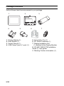
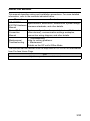
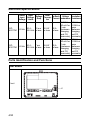
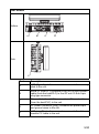
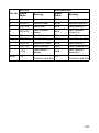
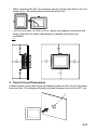
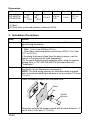
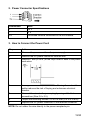
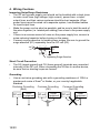
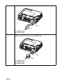
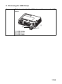
GP-4201TM/4301TM Installation Guide
Please read the "Warning/Caution Information" on the attached sheet
before using the product.
Table of Contents
Package Contents. . . . . . . . . . . . . . . . . . . . . . . . . . . . . . . . . . . . . . . . . . . . . . 2
About the Manual . . . . . . . . . . . . . . . . . . . . . . . . . . . . . . . . . . . . . . . . . . . . . . 3
Electrical Specifications . . . . . . . . . . . . . . . . . . . . . . . . . . . . . . . . . . . . . . . . . 4
Parts Identification and Functions. . . . . . . . . . . . . . . . . . . . . . . . . . . . . . . . . . 4
Serial Interface . . . . . . . . . . . . . . . . . . . . . . . . . . . . . . . . . . . . . . . . . . . . . . . . 6
Installation. . . . . . . . . . . . . . . . . . . . . . . . . . . . . . . . . . . . . . . . . . . . . . . . . . . . 8
1. Installation Requirements . . . . . . . . . . . . . . . . . . . . . . . . . . . . . . . . . . . . 8
2. Panel Cut-out Dimensions. . . . . . . . . . . . . . . . . . . . . . . . . . . . . . . . . . . . 9
3. Installation Procedures . . . . . . . . . . . . . . . . . . . . . . . . . . . . . . . . . . . . . 10
Wiring . . . . . . . . . . . . . . . . . . . . . . . . . . . . . . . . . . . . . . . . . . . . . . . . . . . . . . 12
1. Power Cord Specifications . . . . . . . . . . . . . . . . . . . . . . . . . . . . . . . . . . 12
2. Power Connector Specifications . . . . . . . . . . . . . . . . . . . . . . . . . . . . . . 13
3. How to Connect the Power Cord. . . . . . . . . . . . . . . . . . . . . . . . . . . . . . 13
4. Wiring Cautions . . . . . . . . . . . . . . . . . . . . . . . . . . . . . . . . . . . . . . . . . . . 14
USB Clamp . . . . . . . . . . . . . . . . . . . . . . . . . . . . . . . . . . . . . . . . . . . . . . . . . . 15
1. Attaching the USB Clamp . . . . . . . . . . . . . . . . . . . . . . . . . . . . . . . . . . . 15
2. Removing the USB Clamp . . . . . . . . . . . . . . . . . . . . . . . . . . . . . . . . . . 17
Relevant Standards . . . . . . . . . . . . . . . . . . . . . . . . . . . . . . . . . . . . . . . . . . . 18
1/20
Package Contents
Verify all items listed here are present in your package:
1
2
3
4
Display Module (1)
Rear Module (1)
Socket Wrench (1)
USB Clamp Type A (1 port) (1)
2/20
5 Anti-rotation Tee (1)
6 DC Power Connector (1)
7 Display Installation Nut
(1, attached to the Display Module)
8 GP-4201TM/4301TM Installation
Guide (1) <this guide>
9 Warning/ Caution Information (1)
About the Manual
This manual describes wiring and installation procedures. For more detailed
information, refer to the manuals indicated below.
Manual
Contents
GP-4201TM/
Specifications, dimensions, accessories, system design,
4301TM Hardware
overseas standards, and other details.
Manual
Device/PLC
Connection
Manual
System configuration of connected devices (PLCs and
other devices), communication settings examples,
connection wiring diagram, and other details.
Maintenance/
Troubleshooting
• Troubleshooting
Help for solving problems.
• Maintenance
Details on the GP unit's Offline Mode
The manuals can be selected from the help menu of GP-Pro EX or downloaded
from Pro-face Home Page.
URL
http://www.pro-face.com/otasuke/
3/20
Electrical Specifications
Rated
Input
Power
In-Rush Voltage Insulation
Voltage
Input Voltage
ConsumpCurrent endurance Resistance
Drop
Voltage Limits
tion
GP20.4...
10 ms
24 Vdc
4201TM
28.8 Vdc or less
20.4...
7 ms
GP24 Vdc
28.8 Vdc or less
4301TM
6.5 W
or less
6.8 W
or less
30 A
or less
1,000 Vac
20 mA for
1 min
(between
charging
and FG
terminals)
500 Vdc,
10 MΩ or
more
(between
charging
and FG
terminals)
30 A
or less
1,000 Vac
20 mA for
1 min
(between
charging
and FG
terminals)
500 Vdc,
10 MΩ or
more
(between
charging
and FG
terminals)
Parts Identification and Functions
Rear Module
Front
E
4/20
Rear Module
Bottom
A
B
C
D
Side
E
Part
Description
A
USB (Type A) interface connector: connects the memory
stick to the unit.
B
Serial I/F (host I/F): connects a RS232C/RS422/RS485
cable (from the host/PLC) to the GP unit. D-Sub 9-pin
plug type connector.
C
Ethernet Interface (LAN): connects an Ethernet cable
(from the host/PLC) to the unit.
D
DC Power Connector (plug) :connects the power input
and ground wires to the unit.
E
USB (mini-B) interface connector: connects the data
transfer PC cable to the unit.
5/20
Serial Interface
NOTE: For instructions on how to connect to other devices, always refer to the
"GP-Pro EX Device/PLC Connection Manual".
DANGER
ELECTRIC SHOCK
The serial port is not isolated. The SG (signal ground) and the FG (frame
ground) terminals are connected inside the unit. When using the SG terminal
to connect an external device to the unit:
• Verify that a short-circuit loop is not created when you set up the system.
• Connect the #5 SG terminal to remote equipment when the host (PLC)
unit is not isolated. Connect the #5 SG terminal to a known reliable
ground connection to reduce the risk of damaging the RS232C/RS422/
RS485 circuit.
Failure to follow these instructions will result in death or serious injury.
CAUTION
LOSS OF COMMUNICATION
•
•
All connections to the communication ports must not put excessive stress
on the ports.
Securely attach communication cables to the panel or cabinet.
Failure to follow these instructions can result in injury or equipment
damage.
GP-4201TM/4301TM: D-Sub 9 pin plug connector via an RS-232C/RS-422/
RS-485 cable.
Interfit bracket is #4-40 (UNC).
6/20
RS-232C
Pin No. Signal
Name
RS-422/RS-485
Meaning
Signal
Name
Meaning
1
CD
Carrier Detect
RDA
Receive Data A(+)
2
RD(RXD)
Receive Data
RDB
Receive Data B(-)
3
SD(TXD)
Send Data
SDA
Send Data A(+)
4
ER(DTR)
Data Terminal
Ready
ERA
Data Terminal
Ready A(+)
5
SG
Signal Ground
SG
Signal Ground
6
DR(DSR)
Data Set Ready
CSB
Send Possible B(-)
7
RS(RTS)
Request to Send
SDB
Send Data B(-)
8
CS(CTS)
Send Possible
CSA
Send Possible A(+)
9
CI(RI)
Called status
display
ERB
Data Terminal
Ready B(-)
Shell
FG
Frame Ground
FG
(Common with SG)
Frame Ground
(Common with SG)
7/20
Installation
1. Installation Requirements
Mount the unit in an enclosure that provides a clean, dry, robust and controlled
environment (IP65f enclosure or UL508 4x, if indoors.)
Before installing the GP unit verify that:
• The gasket is flat and not damaged.
• The installation panel or cabinet surface is flat (planarity tolerance: 0.5 mm
(0.019 in.)), in good condition and has no jagged edges. Metal reinforcing
strips may be attached to the inside of the panel, near the panel cut-out, to
increase the rigidity.
• The panel must be designed to avoid any induced vibration resonance on
the rear module exceeding a punctual factor of 10 and to avoid any
induced permanent vibration resonance.
To reduce the resonance use the spacer supplied in the Accessories kit
(sold separately).
• The ambient operating temperature and the ambient humidity are within
their specified ranges.(Surrounding air temperature: 0 to 50°C (32 to
122oF), Ambient humidity :85%RH, Wet bulb temperature: 39°C (102.2°F )
max.)
• The heat from surrounding equipment does not cause the unit to exceed
its specified operating temperature (Surrounding air temperature: 0 to
50°C (32 to 122°F).
• The panel face is not inclined more than 30° when installing the unit in a
slanted panel:
30° or less
8/20
•
•
•
•
•
•
•
•
•
When mounting the GP unit vertically, ensure that the right side of the unit
faces up (i.e. the yellow button should be at the left).
The unit is at least 100 mm (3.94 in.) away from adjacent structures and
other equipment for easier maintenance, operation and improved
ventilation:
PP
LQ
2. Panel Cut-out Dimensions
Create a panel cut-out and insert the display module of the unit into the panel
from the front. The following illustration shows the panel cut-out for a GP unit :
%
$
9/20
Dimensions
Unit
A (mm)
GP-4201TM
GP-4301TM
+0
+0
1.5 to 6
0.88
22.50
-0.01
-0.30
A (in.)
B (mm) (1) B (in.)(1)
0.06 to
0.23
B (mm) (2) B (in.) (2)
3 to 6
0.11 to
0.23
The material of the panel
(1) Steel
(2) Glass fiber reinforced plastics (minimum GF30)
3. Installation Procedures
Step
Action
1
Place the unit on a clean and level surface with the display
panel facing downward.
2
The panel thickness depends on the material:
• Steel: 1.5 to 6 mm (0.06 to 0.23 in.)
• Glass fiber reinforced plastics (minimum GF30): 3 to 6 mm
(0.11 to 0.23 in.)
If the panel thickness is less than the above values, use the
spacer in Accessories kit (sold separately).
For the panel thickness and materials when using the spacer,
please refer to "GP-4201TM/4301TM Hardware Manual""Installation".
Create the correct sized holes required to install the unit, using
the Panel Cut-out Dimension (see page 9).
NOTE: The field wiring opening for controller when mounted
onto an enclosure shall have an area of not more than 775 mm2
(1.2 in2).
3
4
Insert the display module into the panel hole:
Panel
Nut
Socket
Wrench
Screw the nut with the socket wrench with a torque between 1.2
and 2 N•m (10.62 and 17.70 in-lb)
10/20
5
Insert and push the rear module until it locks into place:
NOTE: Install the display module and the rear module unit in
the orientation shown in the illustration. If either unit is installed
incorrectly, the connector may be damaged.
&OLFN
Insert and
push
Free
6
Locked
To remove the rear module, push the yellow button to unlock it,
then pull the rear module out:
Push
Pull
Locked
Unlocked
Free
NOTE:
An Anti-rotation Tee is included in the package. It's appropriate for installing the GP unit
horizontally into the panel. Please see "GP-4201TM/4301TM Hardware Manual" about
how to use the Anti-rotation Tee.
11/20
Wiring
WARNING
HAZARD OF ELECTRIC SHOCK
•
•
•
•
When the frame ground (FG) terminal is connected, verify the wire is
grounded. Not grounding the unit can result in excessive Electromagnetic
Interference (EMI). Grounding is required to meet EMC level immunity.
Remove power before wiring to the power terminals of the unit.
The unit uses only 24 Vdc power. Using any other level of power can
damage both the power supply and the unit.
Since there is no power switch on the GP unit, be sure to attach a breakertype switch to its power cord.
Failure to follow these instructions can result in death, serious injury,
or equipment damage.
NOTE: The shield ground (SG) and FG terminals are connected internally in
the unit.
1. Power Cord Specifications
Use copper conductors only.
Power Cord Diameter 0.75 to 2.5mm2 (18 - 12AWG)
Conductor type
Conductor Length
Simple or Stranded Wire*1
7mm
[0.28in]
*1. If the Conductor's end (individual) wires are not twisted
correctly, the end wires may either short against each other, or
against an electrode.
12/20
2. Power Connector Specifications
Connection
Wire
+
24 V
-
0V
FG
Grounded terminal connected to the unit chassis.
3. How to Connect the Power Cord
Step
Action
1
Remove the power cord from the power supply.
2
Remove the DC power connector from the unit.
3
Remove 7 mm (0.28 in.) of the vinyl cover of each of the power
cord wires.
4
If using stranded wire, twist the ends. Tinning the ends with
solder reduces the risk of fraying and enhances electrical
transfer.
5
Connect the wires to the power plug by using a flat-blade
screwdriver (Size 0.6 x 3.5).
6
Torque the mounting screws: 0.5 to 0.6 N•m (4.4 to 5.2 lb-in).
7
Replace the DC power connector to the terminal connector.
NOTE: Do not solder the wire directly to the power receptacle pin.
13/20
4. Wiring Cautions
Improving Noise/Surge Resistance
• The GP unit's power supply cord should not be bundled with or kept close
to main circuit lines (high voltage, high current), power lines, or input/
output lines, and their various systems should be kept separate. When
power lines cannot be wired via a separate system, use shielded cables
for input/output lines.
• Make the power cord as short as possible, and be sure to twist the ends of
the wires together (i.e. twisted pair cabling) from close to the power supply
unit.
• If there is an excess amount of noise on the power supply line, connect a
noise reducing transistor before turning on the power.
• Connect a surge absorber to handle power surges. Be sure to ground the
surge absorber (E1) separately from the GP unit (E2).
GP
FG
E1
E2
Lightening Surge Absorber
Short Circuit Prevention
• The SG (signal ground) and FG (frame ground) terminals are connected
internally in the GP unit. When connecting the SG line to another device,
be sure that no shorting loops are formed.
Grounding
• Use an exclusive grounding wire with a grounding resistance of 100Ω or
greater and a wire of 2mm2 or thicker, or your country's applicable
standard.
Exclusive Grounding
(Best)
Other
GP unit Equipment
14/20
Common Grounding
(OK)
Other
GP unit Equipment
Common Grounding
(Not OK)
Other
GP unit
Equipment
USB Clamp
When using a USB device, you can attach a USB clamp to the USB interface
to prevent the USB cable from being disconnected.
WARNING
RISK OF EXPLOSION IN HAZARDOUS LOCATIONS
In hazardous locations as described in ANSI/ISA - 12.12.01:
• confirm that the USB cable has been attached with the USB cable clamp
before using the USB host interface.
• remove power before attaching or detaching any connector(s) to or from
the unit.
Failure to follow these instructions can result in death, serious injury,
or equipment damage.
1. Attaching the USB Clamp
Step
Action
1
Attach the USB holder to the USB Host Interface on the rear
module. Hook the upper pick of the USB holder to the
attachment hole of the main unit, and insert the lower pick as
shown below to fix the USB holder.
(1)
(1) USB Holder
15/20
2
Insert the USB cable into the USB host interface.
(1)
(2)
(1) USB Holder
(2) USB Cable
3
Attach the USB cover to fix the USB cable in place. Insert the
USB cover into the tab of the USB holder.
(3)
(1)
(2)
(1) USB Holder
(2) USB Cover
(3) USB Cable
16/20
2. Removing the USB Clamp
1
Push down the tab of the USB holder and then remove the USB
cover.
(1)
(2)
(3)
(1) USB Holder
(2) USB Cover
(3) USB Cable
17/20
Relevant Standards
GP-4201TM and GP-4301TM are manufactured in accordance with:
• Standard UL 508 and CSA C22.2 n°142 for Industrial Control Equipment
• UL1604, ANSI/ISA - 12.12.01 and CSA C22.2 n°213 for Electrical
Equipment for Use in Class I, Division 2 Groups A, B, C and D Hazardous
(classified) Locations
NOTE:
•For use in Pollution Degree 2 environments.
•For use on a flat surface of Type 4X (Indoor Use Only) Enclosure.
WARNING
RISK OF EXPLOSION IN HAZARDOUS LOCATIONS
• Verify the power, input, and output (I/O) wiring are in accordance with
Class I, Division 2 wiring methods.
• Do not substitute components that impair compliance to Class I, Division
2.
• Do not connect or disconnect equipment unless power has been
switched off or the area is non-hazardous.
• Do not disconnect while circuit is live.
• Securely lock externally connected units and each interface before
turning on the power supply.
• The USB2 connector is for temporary connection only during
maintenance and setup of the device. Do not use, connect, or disconnect
USB2 cable unless area is known to be non-hazardous.
• Potential electrostatic charging hazard: wipe the front panel of the
terminal with a damp cloth before turning ON.
Failure to follow these instructions can result in death, serious injury,
or equipment damage.
18/20
CAUTION
ENVIRONMENTAL HAZARDS TO THE EQUIPMENT
• Allow the device to reach the surrounding air temperature, not exceeding
50°C (122°F), before turning the device on.
• Do not turn on the device if condensation has occurred inside the device.
After it is completely dry again, the device may be turned on.
• Do not expose the device to direct sunlight.
• Do not obstruct the vents in the device casing.
• Remove any dust from the device before turning it on.
• Ensure that the cable installation fasteners are not damaged. Replace
them, if necessary.
Failure to follow these instructions can result in injury or equipment
damage.
GP-4201TM and GP-4301TM must be installed, used and maintained in
accordance with:
• Standard WEEE, Directive 2002/96/EC
• Standard RoHS, Directive 2002/95/EC
• Standard RoHS China, Standard SJ/T 11363-2006
NOTE
Please be aware that Digital Electronics Corporation shall not be held liable
by the user for any damages, losses, or third party claims arising from the
uses of this product.
Digital Electronics Corporation
8-2-52 Nanko-higashi
Suminoe-ku, Osaka 559-0031
JAPAN
TEL: +81-(0)6-6613-3116
FAX: +81-(0)6-6613-5888
http://www.pro-face.com
The information in this document is subject to change without notice.
©Copyright 2011 Digital Electronics Corporation. All rights reserved.
19/20
Printed in China
S1B3350601 GP4X01TM-MT01-BTH-CP MI/B
20/20
09/2011