1
Getting Started Guide
Unidrive M700
Unidrive M701
Part Number: 0478-0001-05
Issue: 5
www.controltechniques.com
For the purposes of compliance with the EC Machinery Directive 2006/42/EC:
General Information
This guide covers the basic information that is required to set-up and run the drive, in applications where a
drive malfunction does not result in a mechanical hazard. When the drive is used in a safety related
application, i.e. where a malfunction might result in a hazard, it is essential to refer to the full user guide. The
Unidrive M700 / M701 User Guide is available for download from www.controltechniques.com/userguides.
The manufacturer accepts no liability for any consequences resulting from inappropriate, negligent or
incorrect installation or adjustment of the optional operating parameters of the equipment or from
mismatching the variable speed drive with the motor.
The contents of this guide are believed to be correct at the time of printing. In the interests of a commitment
to a policy of continuous development and improvement, the manufacturer reserves the right to change the
specification of the product or its performance, or the contents of the guide, without notice.
All rights reserved. No parts of this guide may be reproduced or transmitted in any form or by any means,
electrical or mechanical including photocopying, recording or by an information storage or retrieval system,
without permission in writing from the publisher.
Drive firmware version
This product is supplied with the latest firmware version. If this drive is to be connected to an existing system
or machine, all drive firmware versions should be verified to confirm the same functionality as drives of the
same model already present. This may also apply to drives returned from a Control Techniques Service
Centre or Repair Centre. If there is any doubt please contact the supplier of the product.
The firmware version of the drive can be checked by looking at Pr 11.029
The firmware version of the Ethernet interface can be checked by looking at Pr 24.002
Environmental statement
Control Techniques is committed to minimising the environmental impacts of its manufacturing operations
and of its products throughout their life cycle. To this end, we operate an Environmental Management System
(EMS) which is certified to the International Standard ISO 14001. Further information on the EMS, our
Environmental Policy and other relevant information is available on request, or can be found at
www.greendrives.com.
The electronic variable-speed drives manufactured by Control Techniques have the potential to save energy
and (through increased machine/process efficiency) reduce raw material consumption and scrap throughout
their long working lifetime. In typical applications, these positive environmental effects far outweigh the
negative impacts of product manufacture and end-of-life disposal.
Nevertheless, when the products eventually reach the end of their useful life, they must not be discarded but
should instead be recycled by a specialist recycler of electronic equipment. Recyclers will find the products
easy to dismantle into their major component parts for efficient recycling. Many parts snap together and can
be separated without the use of tools, while other parts are secured with conventional fasteners. Virtually all
parts of the product are suitable for recycling.
Product packaging is of good quality and can be re-used. Large products are packed in wooden crates, while
smaller products come in strong cardboard cartons which themselves have a high recycled fibre content. If
not re-used, these containers can be recycled. Polythene, used on the protective film and bags for wrapping
product, can be recycled in the same way. Control Techniques' packaging strategy prefers easily-recyclable
materials of low environmental impact, and regular reviews identify opportunities for improvement.
When preparing to recycle or dispose of any product or packaging, please observe local legislation and best
practice.
REACH legislation
EC Regulation 1907/2006 on the Registration, Evaluation, Authorisation and restriction of Chemicals
(REACH) requires the supplier of an article to inform the recipient if it contains more than a specified
proportion of any substance which is considered by the European Chemicals Agency (ECHA) to be a
Substance of Very High Concern (SVHC) and is therefore listed by them as a candidate for compulsory
authorisation.
For current information on how this requirement applies in relation to specific Control Techniques products,
please approach your usual contact in the first instance. Control Techniques position statement can be
viewed at:
http://www.controltechniques.com/REACH
Copyright
© August 2012 Control Techniques Ltd
Issue Number: 5
Drive Firmware:00.10.00.00 onwards
Ethernet Firmware: 01.00.02.02 onwards
Contents
1
2
Safety information .......................................................................................4
Product information ....................................................................................7
3
Mechanical installation .............................................................................14
4
Electrical installation .................................................................................20
5
Getting started ........................................................................................... 30
6
Basic parameters (Menu 0) .......................................................................36
7
Running the motor ....................................................................................44
8
NV Media Card Operation .........................................................................54
9
Further information ...................................................................................56
2.1
2.2
2.3
2.4
2.5
3.1
3.2
3.3
3.4
3.5
3.6
3.7
4.1
4.2
4.3
4.4
4.5
4.6
4.7
4.8
4.9
5.1
5.2
5.3
5.4
5.5
5.6
5.7
5.8
5.9
5.10
5.11
6.1
7.1
7.2
8.1
8.2
8.3
9.1
Model number .......................................................................................................... 7
Nameplate description ............................................................................................. 7
Ratings .................................................................................................................... 8
Drive features ........................................................................................................ 11
Options / Accessories ............................................................................................ 12
Safety information .................................................................................................. 14
Fire protection ........................................................................................................ 14
Mounting methods ................................................................................................. 14
Drive dimensions ................................................................................................... 15
Surface mounting .................................................................................................. 16
Enclosure ............................................................................................................... 17
EMC filters ............................................................................................................. 18
Supply types .......................................................................................................... 21
Ratings .................................................................................................................. 21
Power connections ................................................................................................ 22
Ground connections .............................................................................................. 25
Position feedback connections .............................................................................. 25
Braking resistor values ......................................................................................... 27
Communications connections ................................................................................ 28
Shield connections ................................................................................................ 28
Control connections ............................................................................................... 29
Understanding the display ..................................................................................... 30
Keypad operation .................................................................................................. 31
Menu 0 ................................................................................................................... 32
Menu structure ....................................................................................................... 32
Advanced menus ................................................................................................... 33
Changing the operating mode ............................................................................... 34
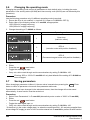
Saving parameters ................................................................................................ 34
Restoring parameter defaults ................................................................................ 35
Displaying parameters with non-default values only .............................................. 35
Displaying destination parameters only ................................................................. 35
Parameter access level and security ..................................................................... 35
Parameter descriptions .......................................................................................... 39
Quick start Connections ........................................................................................ 44
Quick Start / start-up ............................................................................................. 47
Introduction ............................................................................................................ 54
SMARTCARD support ........................................................................................... 55
Transferring data ................................................................................................... 55
Diagnostics ............................................................................................................ 56
Unidrive M700 Getting Started Guide
Issue Number: 5
1
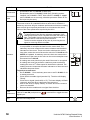
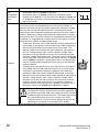
Safety information
1.1
Warnings, Cautions and Notes
A Warning contains information which is essential for avoiding a safety hazard.
WARNING
A Caution contains information which is necessary for avoiding a risk of damage to the
product or other equipment.
CAUTION
NOTE
1.2
A Note contains information, which helps to ensure correct operation of the product.
Electrical safety - general warning
The voltages used in the drive can cause severe electrical shock and/or burns, and could be lethal.
Extreme care is necessary at all times when working with or adjacent to the drive. Specific warnings
are given at the relevant places in this guide.
1.3
System design and safety of personnel
The drive is intended as a component for professional incorporation into complete equipment or a
system. If installed incorrectly, the drive may present a safety hazard.
The drive uses high voltages and currents, carries a high level of stored electrical energy, and is used
to control equipment which can cause injury.
Close attention is required to the electrical installation and the system design to avoid hazards either
in normal operation or in the event of equipment malfunction. System design, installation,
commissioning/start-up and maintenance must be carried out by personnel who have the necessary
training and experience. They must read this safety information and this User Guide carefully.
The STOP and SAFE TORQUE OFF functions of the drive do not isolate dangerous voltages from
the output of the drive or from any external option unit. The supply must be disconnected by an
approved electrical isolation device before gaining access to the electrical connections.
With the sole exception of the SAFE TORQUE OFF function, none of the drive functions must
be used to ensure safety of personnel, i.e. they must not be used for safety-related functions.
Careful consideration must be given to the functions of the drive which might result in a hazard,
either through their intended behavior or through incorrect operation due to a fault. In any application
where a malfunction of the drive or its control system could lead to or allow damage, loss or injury, a
risk analysis must be carried out, and where necessary, further measures taken to reduce the risk for example, an over-speed protection device in case of failure of the speed control, or a fail-safe
mechanical brake in case of loss of motor braking.
The SAFE TORQUE OFF function may be used in a safety-related application. The system designer
is responsible for ensuring that the complete system is safe and designed correctly according to the
relevant safety standards.
1.4
Environmental limits
Instructions in this guide regarding transport, storage, installation and use of the drive must be
complied with, including the specified environmental limits. Drives must not be subjected to
excessive physical force.
4
Unidrive M700 Getting Started Guide
Issue Number: 5
Access
Drive access must be restricted to authorized personnel only. Safety regulations which apply at the
place of use must be complied with.
1.6
Fire protection
1.7
Compliance with regulations
This guide contains instruction for achieving compliance with specific EMC standards.
Within the European Union, all machinery in which this product is used must comply with the
following directives:
1.8
Electrical installation
2006/42/EC: Safety of machinery.
2004/108/EC: Electromagnetic Compatibility.
Motor
Ensure the motor is installed in accordance with the manufacturer’s recommendations. Ensure the
motor shaft is not exposed.
The values of the motor parameters set in the drive affect the protection of the motor. The default
values in the drive should not be relied upon.
It is essential that the correct value is entered in Pr 00.046 motor rated current. This affects the
thermal protection of the motor.
NV Media Card
Operation
1.10
Running the motor
Mechanical brake control
The brake control functions are provided to allow well co-ordinated operation of an external brake
with the drive. While both hardware and software are designed to high standards of quality and
robustness, they are not intended for use as safety functions, i.e. where a fault or failure would result
in a risk of injury. In any application where the incorrect operation of the brake release mechanism
could result in injury, independent protection devices of proven integrity must also be incorporated.
Basic parameters
Low speeds may cause the motor to overheat because the cooling fan becomes less effective. The
motor should be installed with a protection thermistor. If necessary, an electric forced vent fan should
be used.
Getting started
Standard squirrel cage induction motors are designed for single speed operation. If it is intended to
use the capability of the drive to run a motor at speeds above its designed maximum, it is strongly
recommended that the manufacturer is consulted first.
1.9
Mechanical
installation
The installer is responsible for complying with all relevant regulations, such as national wiring
regulations, accident prevention regulations and electromagnetic compatibility (EMC) regulations.
Particular attention must be given to the cross-sectional areas of conductors, the selection of fuses
or other protection, and protective ground (earth) connections.
Product information
The drive enclosure is not classified as a fire enclosure. A separate fire enclosure must be provided.
For further information, refer to the Unidrive M700 / M701 User Guide.
Safety information
1.5
Adjusting parameters
Some parameters have a profound effect on the operation of the drive. They must not be altered
without careful consideration of the impact on the controlled system. Measures must be taken to
prevent unwanted changes due to error or tampering.
Further information
Unidrive M700 Getting Started Guide
Issue Number: 5
5
1.11
Electrical installation
1.11.1
Electric shock risk
The voltages present in the following locations can cause severe electric shock and may be lethal:
• AC supply cables and connections
• Output cables and connections
• Many internal parts of the drive, and external option units
Unless otherwise indicated, control terminals are single insulated and must not be touched.
1.11.2
Stored charge
The drive contains capacitors that remain charged to a potentially lethal voltage after the AC supply
has been disconnected. If the drive has been energized, the AC supply must be isolated at least ten
minutes before work may continue.
6
Unidrive M700 Getting Started Guide
Issue Number: 5
Product information
This guide covers the Unidrive M700 and the Unidrive M701 products. The Unidrive M700 product
offers Ethernet fieldbus communications and the Unidrive M701 offers a 2 wire 485 serial interface.
All other features of these two products are exactly the same.
Model number
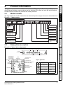
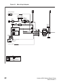
The way in which the model numbers for the Unidrive M product range is formed is illustrated below:
Figure 2-1
Model number
Identification Label
Derivative
Electrical Specifications
M700 -
03 4
00078
Reserved
A
1
Optional Build
Documentation Customer Code
0
1
A
01
B
1
0
0
Reserved:
Conformal Coating:
Frame Size:
IP / NEMA Rating:
Mechanical
installation
Unidrive M
Product Line
700 - Ethernet
701 - 485
702 - Ethernet, 2 x STO
0 = Standard
Electrical installation
0 = IP21 / NEMA 1
Voltage Rating:
Brake Transistor:
2 - 200 V (200 - 240 ± 10 %)
4 - 400 V (380 - 480 ± 10 %)
5 - 575 V (500 - 575 ± 10 %
6 - 690 V (500 - 690 ± 10 %)
B = Brake
Cooling:
A = Air
Customer Code:
Heavy Duty current rating x 10
00 = 50 Hz
01 = 60 Hz
Drive Format:
Documentation:
A - AC in AC out
0 - Supplied separately
1 - English
Getting started
Current Rating:
2.2
Nameplate description
Typical drive rating labels
Model
Frame
size
Basic parameters
Figure 2-2
Heavy Duty
current rating
Refer to
User Guide
Input
frequency
Drive format
Running the motor
Voltage
Heavy Duty /
Normal Duty
power rating
Product information
2.1
Safety information
2
Customer and
date code
Input voltage
No.of phases &
Typical input current for
Normal Duty rating
Output
voltage
Approvals
Unidrive M700 Getting Started Guide
Issue Number: 5
Europe
C Tick approval
Australia
UL / cUL approval
USA & Canada
RoHS compliant
Europe
CSA approval
Canada
Further information
Serial
number
R
CE approval
NV Media Card
Operation
Heavy Duty /
Normal Duty rating
output current
Key to approvals
7
2.3
WARNING
NOTE
Table 2-1
Ratings
Fuses
The AC supply to the drive must be installed with suitable protection against overload and
short-circuits. The following section shows recommended fuse ratings. Failure to observe
this requirement will cause risk of fire.
Nominal cables sizes below are provided as a guide only. Ensure cables used suit local
wiring regulations.
200 V drive ratings, cable sizes and fuse ratings
Max.
cont.
input
current
Model
3ph
03200050
03200066
03200080
03200106
04200137
04200185
06200330
06200440
Table 2-2
A
A
A
16
20
25
25
25
32
63
63
16
20
25
25
25
30
60
70
Normal Duty
USA
Heavy Duty
mm2
1.5
1.5
4
4
6
8
16
25
mm2 AWG AWG
1.5
14
14
1.5
14
14
4
12
12
4
12
12
6
10
10
8
8
8
16
4
4
25
3
3
A
kW
hp
A
kW
hp
6.6
8.0
11.0
12.7
18.0
24.0
50.0
58.0
1.1
1.5
2.2
3.0
4.0
5.5
11.0
15.0
1.5
2.0
3.0
3.0
5.0
7.5
15.0
20.0
5
6.6
8.0
10.6
13.7
18.5
33.0
44.0
0.75
1.1
1.5
2.2
3.0
4.0
7.5
11.0
1.0
1.5
2.0
3.0
3.0
5.0
10.0
15.0
400 V drive ratings, cable sizes and fuse ratings
Model
3ph
8
European
Nom Motor
Nom Motor Max.
Max.
Class
cont. power power cont. power power
Input
Output
Input
Output
IEC CC or
@
@
output
@
@
output
gG Class
230V
current 230V 230V current 230V
J
10.7
13
17.8
20.6
20.1
26.8
48.8
56.6
Max.
cont.
input
current
03400025
03400031
03400045
03400062
03400078
03400100
04400150
04400172
Nominal cable size
Fuse
Nominal cable size
Fuse
European
Normal Duty
USA
Heavy Duty
Nom Motor
Nom Motor Max.
Max.
Class
cont. power power cont. power power
IEC CC or Input Output Input Output output
@
@
output
@
@
gG Class
460V
current 400V 460V current 400V
J
A
A
A
5
6.6
9.1
13.1
13.4
15.8
18.7
24.3
6
10
10
20
20
20
25
32
10
10
10
20
20
20
25
30
mm2
1.5
1.5
1.5
2.5
2.5
2.5
6
8
mm2 AWG AWG
1.5
18
18
1.5
16
16
1.5
14
14
2.5
14
14
2.5
14
14
2.5
12
12
6
10
10
8
8
8
A
kW
hp
A
kW
hp
3.4
4.5
6.2
7.7
10.4
12.3
18.5
24.0
1.1
1.5
2.2
3.0
4.0
5.5
7.5
11.0
1.5
2.0
3.0
5.0
5.0
7.5
10.0
15.0
2.5
3.1
4.5
6.2
7.8
10.0
15.0
17.2
0.75
1.1
1.5
2.2
3.0
4.0
5.5
7.5
1.0
1.5
2.0
3.0
5.0
5.0
10.0
10.0
Unidrive M700 Getting Started Guide
Issue Number: 5
Max.
cont.
input
current
Model
06400350
06400420
06400470
Heavy Duty
Nom Motor Max. Nom Motor
Max.
Ferraz
cont. power power cont. power power
HSJ Input Output Input Output output
IEC
@
@
@ output
@
gR Bussman
current 400V 460V current 400V 460V
DFJ
A
A
A
36.5
46.2
60.6
63
63
63
40
50
70
mm2
10
16
25
mm2 AWG AWG
10
6
6
16
4
4
25
3
3
A
kW
hp
A
kW
hp
38.0
48.0
63.0
18.5
22.0
30.0
25.0
30.0
40.0
35.0
42.0
47.0
15.0
18.5
22.0
25.0
30.0
30.0
575 V drive ratings, cable sizes and fuse ratings
Max.
cont.
input
current
3ph
Nominal cable size
Fuse
European
Normal Duty
USA
Heavy Duty
Nom Motor
Nom Motor Max.
Max.
Class
cont. power power cont. power power
IEC CC or Input Output Input Output output
@
@
output
@
@
gG Class
575V
current 575V 575V current 575V
J
A
A
20
32
40
50
50
63
20
25
30
35
40
50
mm2
2.5
4
6
10
10
16
mm2 AWG AWG
2.5
14
14
4
10
10
6
10
10
10
8
8
10
6
6
16
6
6
A
kW
hp
A
kW
hp
12.0
17.0
22.0
27.0
34.0
43.0
7.5
11.0
15.0
18.5
22.0
30.0
10.0
15.0
20.0
25.0
30.0
40.0
10.0
15.0
19.0
23.0
29.0
35.0
5.5
7.5
11.0
15.0
18.5
22.0
7.5
10.0
15.0
20.0
25.0
30.0
Getting started
A
13.2
18.7
24.3
29.4
37.1
46.9
Electrical installation
Model
06500100
06500150
06500190
06500230
06500290
06500350
Normal Duty
USA
Mechanical
installation
Table 2-4
European
Product information
3ph
Nominal cable size
Fuse
Safety information
Table 2-3 400 V drive ratings, cable sizes and fuse ratings (size 6 only)
Basic parameters
Running the motor
NV Media Card
Operation
Further information
Unidrive M700 Getting Started Guide
Issue Number: 5
9
Table 2-5
Protective ground cable ratings
Model
Ground conductor size
03200050, 03200066, 03200080, 03200106,
04200137, 04200185, 06200330
Either use 10 mm2 cable or 2 cables of the same cross
sectional area as the recommended phase cables
06200440
Either use 16 mm2 cable or 2 cables of the same cross
sectional area as the recommended phase cables
03400025, 03400031, 03400045, 03400062,
03400078, 03400100, 04400150, 04400172,
06400420
Either use 10 mm2 cable or 2 cables of the same cross
sectional area as the recommended phase cables
06400470
Either use 16 mm2 cable or 2 cables of the same cross
sectional area as the recommended phase cables
06500100, 06500150, 06500190, 06500230,
06500290, 06500350
Either use 10 mm2 cable or 2 cables of the same cross
sectional area as the recommended phase cables
200 V
400 V
575 V
Typical short term overload limits
The maximum percentage overload limit changes depending on the selected motor. Variations in
motor rated current, motor power factor and motor leakage inductance all result in changes in the
maximum possible overload. Typical values are shown in the table below:
Table 2-6
Typical overload limits
Operating mode
RFC from
cold
RFC from
100 %
Open loop
from cold
Open loop
from 100 %
Normal Duty overload with motor rated current
= drive rated current
110 % for 165 s 110 % for 9 s 110 % for 165 s
110 % for 9 s
Heavy Duty overload with motor rated current
= drive rated current
200 % for 28 s 200 % for 3 s 150 % for 60 s
150 % for 8 s
Generally the drive rated current is higher than the matching motor rated current allowing a higher
level of overload than the default setting.
The time allowed in the overload region is proportionally reduced at very low output frequency on
some drive ratings.
NOTE
The maximum overload level which can be attained is independent of the speed.
Output current
The continuous output current ratings given on the rating label are for maximum 40 °C (104 °F),
1000 m altitude and 2.0 kHz switching. Derating is required for higher switching frequencies, ambient
temperatures >40 °C (104 °F) and higher altitude. For derating information, refer to the Unidrive
M700 / M701 User Guide.
Input current
The input current is affected by the supply voltage and impedance. The input current given on the
rating label is the typical input current and is stated for a balanced supply.
10
Unidrive M700 Getting Started Guide
Issue Number: 5
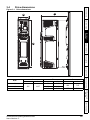
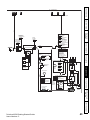
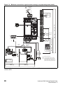
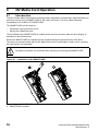
Drive features
Figure 2-3
Safety information
2.4
Features of the drive
Product information
Mechanical
installation
Electrical installation
1. Keypad connection
7. Option module slot 3
13. Braking terminal
2. Rating label
8. Relay connections
14. Internal EMC filter
Getting started
Key
9. Position feedback connections
15. DC bus +
4. Status LED
10. Control connections
16. DC bus -
5. Option module slot 1
11. Communications port
17. AC supply / motor connections
6. Option module slot 2
12. NV media card slot
18. Ground connections
Basic parameters
3. Identification label
Running the motor
NV Media Card
Operation
Further information
Unidrive M700 Getting Started Guide
Issue Number: 5
11
2.5
Options / Accessories
Figure 2-4
Drive features and options
1. Keypad
4. Option module slot 3
2. Option module slot 1
5. CT Comms cable
3. Option module slot 2
6. Internal braking resistor
Table 2-7
7. NV media card
Option module identification
Type
Option module
Feedback
Color
Name
N/A
15-way D-type converter
N/A
Single ended encoder interface (15 V or 24 V)
Fieldbus
Purple
SI-PROFIBUS
Automation
(Applications)
Black
SI-Applications Plus
SI-Applications Lite V2
SI-Register
Table 2-8
Keypad identification
Type
Keypad
12
Keypad
Name
SI-Keypad
Unidrive M700 Getting Started Guide
Issue Number: 5
Parts supplied with the drive
Description
Size 3
Size 4
Safety information
Table 2-9
Size 6
Control connectors
x1
Product information
x1
Relay connector
x1
24 V power supply connector
Mechanical
installation
x1
Electrical installation
Grounding bracket
x1
Surface mounting brackets
x2
Getting started
x2
x2
Grounding clamp
Basic parameters
x1
x1
DC terminal cover grommets
Running the motor
x2
M6 Nuts
x 11
NV Media Card
Operation
M4 x 10 Taptite screws
x2
Supply and motor connector
Further information
x1
Finger guard grommets
x2
Unidrive M700 Getting Started Guide
Issue Number: 5
13
3
Mechanical installation
3.1
Safety information
WARNING
WARNING
Follow the instructions
The mechanical and electrical installation instructions must be adhered to. Any questions
or doubt should be referred to the supplier of the equipment. It is the responsibility of the
owner or user to ensure that the installation of the drive and any external option unit, and
the way in which they are operated and maintained, comply with the requirements of the
Health and Safety at Work Act in the United Kingdom or applicable legislation and
regulations and codes of practice in the country in which the equipment is used.
Stored charge
The drive contains capacitors that remain charged to a potentially lethal voltage after the
AC supply has been disconnected. If the drive has been energized, the AC supply must
be isolated at least ten minutes before work may continue.
Normally, the capacitors are discharged by an internal resistor. Under certain, unusual
fault conditions, it is possible that the capacitors may fail to discharge, or be prevented
from being discharged by a voltage applied to the output terminals. If the drive has failed
in a manner that causes the display to go blank immediately, it is possible the capacitors
will not be discharged. In this case, consult Control Techniques or their authorized
distributor.
WARNING
WARNING
3.2
Competence of the installer
The drive must be installed by professional assemblers who are familiar with the
requirements for safety and EMC. The assembler is responsible for ensuring that the end
product or system complies with all the relevant laws in the country where it is to be used.
Enclosure
The drive is intended to be mounted in an enclosure which prevents access except by
trained and authorized personnel, and which prevents the ingress of contamination. It is
designed for use in an environment classified as pollution degree 2 in accordance with IEC
60664-1. This means that only dry, non-conducting contamination is acceptable.
Fire protection
The drive enclosure is not classified as a fire enclosure. A separate fire enclosure must be provided.
For installation in the USA, a NEMA 12 enclosure is suitable.
For installation outside the USA, refer to the Unidrive M700 / M701 User Guide.
3.3
Mounting methods
Unidrive M700 / M701 size 3, 4 and 6 can be either surface or through-panel mounted using the
appropriate brackets.
WARNING
14
If the drive has been used at high load levels for a period of time, the heatsink can reach
temperatures in excess of 70 °C (158 °F). Human contact with the heatsink should be
prevented.
Unidrive M700 Getting Started Guide
Issue Number: 5
C
B
Product information
Mechanical
installation
Electrical installation
Getting started
Basic parameters
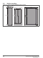
200
7.87
227
8.94
Running the motor
in
14.37
NV Media Card
Operation
Further information
15
Unidrive M700 Getting Started Guide
Issue Number: 5
mm
365
C
B
A
in
3.27
4.88
8.27
mm
83
124
210
in
3
4
6
Drive dimensions
Figure 3-1
mm
Size
Safety information
Drive dimensions
3.4
A
3.5
Surface mounting
Figure 3-2
Surface mounting dimensions (size 3, 4 and 6)
6.0 mm
(0.24 in)
73.0 mm (2.87 in)
Æ 5.5 mm
(0.22 in)
106 mm (4.17 in)
53 mm
53 mm
8 mm
(2.09 in)
(0.32 in) (2.09 in)
370 mm
(14.57 in)
3
375 mm
(14.76 in)
4
196 mm
(7.72 in)
7.0 mm
(0.28 in)
6.0 mm
(0.24 in)
Æ 6.5 mm
(0.26 in) x 4 holes
378 mm
(14.88 in)
6
Æ7.0 mm
(0.27 in)
16
Unidrive M700 Getting Started Guide
Issue Number: 5
Enclosure
Enclosure Layout
Please observe the clearances in the diagram below taking into account any appropriate notes for
other devices / auxiliary equipment when planning the installation.
Figure 3-3 Enclosure layout
Locate
Locateas
as
required
required
Product information
Optional braking resistor and overload
Locate optional braking
resistor external to
cubicle (preferably near to or
on top of the cubicle).
Locate the overload protection
device as required
Enclosure
Ensure minimum clearances
are maintained for the drive
and external EMC filter. Forced
or convection air-flow must not
be restricted by any object or
cabling
A Size 3: ³0mm (0 in)
Electrical installation
A
A
Basic parameters
³100 mm
(4 in)
Note
For EMC compliance:
1) When using an external EMC
filter, one filter is required for
each drive
2) Power cabling must be at
least 100 mm (4 in) from the
drive in all directions
Getting started
The external EMC filter can be
bookcase mounted (next to the
drive) or footprint mounted (with
the drive mounted onto the filter).
External
controller
Mechanical
installation
³100mm
(4in)
AC supply
contactor and
fuses or MCB
Safety information
3.6
Running the motor
Signal cables
Plan for all signal cables
to be routed at least
300 mm (12 in) from the
drive and any power cable
NV Media Card
Operation
Further information
Unidrive M700 Getting Started Guide
Issue Number: 5
17
3.7
EMC filters
3.7.1
Internal filter
It is recommended that the internal EMC filter be kept in place unless there is a specific reason for
removing it. If the drive is part of a regen system or it is connected to an IT supply then the internal
EMC filter must be removed.
The internal EMC filter reduces radio-frequency emission into the line power supply. Where the
motor cable is short, it permits the requirements of EN 61800-3:2004 to be met for the second
environment - for further information see the Unidrive M700 / M701 User Guide. For longer motor
cables the filter continues to provide a useful reduction in emission level, and when used with any
length of shielded motor cable up to the limit for the drive, it is unlikely that nearby industrial
equipment will be disturbed. It is recommended that the filter be used in all applications unless the
instructions given above require it to be removed or the ground leakage current of the drive is
unacceptable.
Figure 3-4
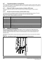
Removal of Size 3 internal EMC filter
Loosen / remove the screw and nut as shown (1) and (2).
Lift away from securing points and then rotate away from the drive. Ensure the screw and nut are
replaced and re-tightened with a maximum torque of 2 N m (1.47 lb ft).
18
Unidrive M700 Getting Started Guide
Issue Number: 5
Removal of size 4 internal EMC filter
Safety information
Figure 3-5
Product information
Mechanical
installation
Electrical installation
To electrically disconnect the Internal EMC filter, remove the screw (1) as highlighted above.
Figure 3-6
Removal of size 6 internal EMC filter
Getting started
Basic parameters
Running the motor
1
To electrically disconnect the Internal EMC filter, remove the screw (1) as highlighted above.
External filter
The external EMC filter for size 3, 4 and 6 can be footprint or bookcase mounted.
For information on drive and EMC filter cross reference, refer to the Unidrive M700 / M701 User Guide.
Further information
To avoid a fire hazard and maintain validity of the UL listing, adhere to the specified
tightening torques for the power and ground terminals.
WARNING
For further information refer to the Unidrive M700 / M701 User Guide.
Unidrive M700 Getting Started Guide
Issue Number: 5
NV Media Card
Operation
3.7.2
19
4
Electrical installation
WARNING
WARNING
WARNING
WARNING
WARNING
WARNING
WARNING
20
Electric shock risk
The voltages present in the following locations can cause severe electric shock and may be
lethal:
AC supply cables and connections
DC and brake cables, and connections
Output cables and connections
Many internal parts of the drive, and external option units
Unless otherwise indicated, control terminals are single insulated and must not be touched.
Isolation device
The AC and / or DC power supply must be disconnected from the drive using an approved
isolation device before any cover is removed from the drive or before any servicing work
is performed.
STOP function
The STOP function does not remove dangerous voltages from the drive, the motor or any
external option units.
SAFE TORQUE OFF function
The SAFE TORQUE OFF function does not remove dangerous voltages from the drive,
the motor or any external option units.
Stored charge
The drive contains capacitors that remain charged to a potentially lethal voltage after the
AC and / or DC power supply has been disconnected. If the drive has been energized,
the AC and / or DC power supply must be isolated at least ten minutes before work may
continue. Normally, the capacitors are discharged by an internal resistor. Under certain,
unusual fault conditions, it is possible that the capacitors may fail to discharge, or be
prevented from being discharged by a voltage applied to the output terminals. If the drive
has failed in a manner that causes the display to go blank immediately, it is possible the
capacitors will not be discharged. In this case, consult Control Techniques or their
authorized distributor.
Equipment supplied by plug and socket
Special attention must be given if the drive is installed in equipment which is connected to
the AC supply by a plug and socket. The AC supply terminals of the drive are connected
to the internal capacitors through rectifier diodes which are not intended to give safety
isolation. If the plug terminals can be touched when the plug is disconnected from the
socket, a means of automatically isolating the plug from the drive must be used (e.g. a
latching relay).
Permanent magnet motors
Permanent magnet motors generate electrical power if they are rotated, even when the
supply to the drive is disconnected. If that happens then the drive will become energized
through its motor terminals. If the motor load is capable of rotating the motor when the
supply is disconnected, then the motor must be isolated from the drive before gaining
access to any live parts.
Unidrive M700 Getting Started Guide
Issue Number: 5
Supply types
All drives are suitable for use on any supply type i.e TN-S, TN-C-S, TT and IT.
Supplies with voltage up to 600 V may have grounding at any potential, i.e. neutral, centre or corner
(“grounded delta”)
Supplies with voltage above 600 V may not have corner grounding
NOTE
Ratings
A fuse or other protection must be included in all live connections to the AC supply.
An MCB (miniature circuit breaker) or MCCB (moulded-case circuit-breaker) with type C may be
used in place of fuses for size 3 under the following conditions:
•
NV Media Card
Operation
Fuses
The AC supply to the drive must be installed with suitable protection against overload and
short-circuits. section 2.3 Ratings on page 8 shows nominal fuse ratings. Failure to
observe this requirement will cause risk of fire.
Running the motor
WARNING
The nominal output cable sizes in section 2.3 Ratings on page 8 assume that the motor
maximum current matches that of the drive. Where a motor of reduced rating is used the
cable rating may be chosen to match that of the motor. To ensure that the motor and cable
are protected against over-load, the drive must be programmed with the correct motor
rated current.
Basic parameters
NOTE
Getting started
See section 2.3 Ratings on page 8.
Maximum continuous input current
The values of maximum continuous input current are given to aid the selection of cables and fuses.
These values are stated for the worst case condition with the unusual combination of stiff supply with
high imbalance. The value stated for the maximum continuous input current would only be seen in
one of the input phases. The current in the other two phases would be significantly lower.
The values of maximum input current are stated for a supply with a 2 % negative phase-sequence
imbalance and rated at the maximum supply fault current given in section 2.3 Ratings on page 8.
The nominal cable sizes in section 2.3 Ratings on page 8 are only a guide. Refer to local wiring
regulations for the correct size of cables. In some cases a larger cable is required to avoid excessive
voltage drop.
Electrical
installation
4.2
If the drive is to be used on an IT (ungrounded) supply, refer to the Unidrive M700 / M701
User Guide for more information.
Mechanical
installation
Drives are suitable for use on supplies of installation category III and lower, according to IEC 60664-1.
This means they may be connected permanently to the supply at its origin in a building, but for outdoor
installation additional over-voltage suppression (transient voltage surge suppression) must be
provided to reduce category IV to category III.
Product information
WARNING
If an SI-Applications Plus or SI-Register module is installed in the drive, then the drive
must not be used on a corner-grounded or centre-grounded delta supply if the supply
voltage is above 300 V. If this is required, please contact the supplier of the drive for more
information.
Safety information
4.1
The fault-clearing capacity must be sufficient for the installation
Further information
Fuse Types
The fuse voltage rating must be suitable for the drive supply voltage.
Unidrive M700 Getting Started Guide
Issue Number: 5
21
4.3
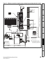
Figure 4-1
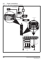
Power connections
Size 3 power and ground connections
DC Connections
Optional
braking
resistor
Thermal
overload
protection
device
BR
+DC
Internal
EMC filter
Ground connection
studs
-DC
Additional ground
connection
3
AC Connections
PE
L1
L2
L3
U
V
W
Optional EMC
filter
Optional
line reactor
Fuses
Motor
L1
Supply
Ground
22
L2
Mains
Supply
L3
Optional ground
connection
Unidrive M700 Getting Started Guide
Issue Number: 5
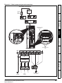
Size 4 power and ground connections
Safety information
Figure 4-2
DC / Brake connections
Thermal
overload
protection
device
Product information
Optional
braking
resistor
+DC
BR
-DC
Mechanical
installation
Additional ground
connection
Electrical
installation
Getting started
4
PE
L1
L2
L3
U
Basic parameters
1
Ground connection
studs
AC Connections
V
W
Running the motor
Optional EMC
filter
Optional
line reactor
NV Media Card
Operation
Fuses
Motor
L2
Mains
Supply
Unidrive M700 Getting Started Guide
Issue Number: 5
L3
Further information
L1
Supply
Ground
Optional ground
connection
23
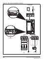
Figure 4-3
Size 6 power and ground connections
DC Connections
(DC and braking)
Thermal
overload
protection
device
DC - DC +
Optional
braking
resistor
BR
6
AC Connections
L1
L2
L3
Motor Connections
PE
U
V
W
Ground connection
studs
Optional EMC
filter
Optional
line reactor
Fuses
Motor
L1
L2
Mains
Supply
24
L3
Supply
Ground
Optional ground
connection
Unidrive M700 Getting Started Guide
Issue Number: 5
WARNING
Ground connections
Electrochemical corrosion of grounding terminals
Ensure that grounding terminals are protected against corrosion i.e. as could be caused
by condensation.
NOTE
For further information on ground cable sizes, refer to Table 2-5 Protective ground cable
ratings on page 10.
WARNING
Position feedback connections
The following functions are provided via the 15-way high density D-type connector on the drive:
Two position feedback interfaces (P1 and P2).
One encoder simulation output.
Two freeze trigger inputs (marker inputs).
One thermistor input.
The P1 position interface is always available but the availability of the P2 position interface and the
encoder simulation output depends on the position feedback device used on the P1 position interface.
Figure 4-4
Refer to the Unidrive M700 / M701 User Guide for information regarding the supported
feedback devices on the P1 and P2 position interface and the encoder stimulation output.
Location of position feedback connection
Front view
End view
Basic parameters
NOTE
Getting started
•
•
•
•
Electrical
installation
4.5
The ground loop impedance must conform to the requirements of local safety regulations.
The drive must be grounded by a connection capable of carrying the prospective fault
current until the protective device (fuse, etc.) disconnects the AC supply.
The ground connections must be inspected and tested at appropriate intervals.
Mechanical
installation
On size 3 and 4, the supply and motor ground connections are made using the M4 studs located
either side of the drive near the plug-in power connectors. See Figure 4-1 for details.
On a size 6, the supply and motor ground connections are made using the M6 studs located above
the supply and motor terminals. Refer to Figure 4-2 above.
Product information
The drive must be connected to the system ground of the AC supply. The ground wiring must
conform to local regulations and codes of practice.
Safety information
4.4
Running the motor
NV Media Card
Operation
1
6
11
Further information
5
10
15
Drive encoder connector
Female 15-way D-type
Unidrive M700 Getting Started Guide
Issue Number: 5
25
4.5.1
Table 4-1
P1 Position
feedback
interface
Pr 03.038
Position feedback connection details
P1 position feedback connection details
Connections
1
2
3
4
5
6
AB (0)
A
A\
B
B\
Z
Z\
FD (1)
F
F\
D
D\
Z
Z\
FR (2)
F
F\
R
R\
Z
Z\
AB Servo (3)
A
A\
B
B\
Z
FD Servo (4)
F
F\
D
D\
FR Servo (5)
7
8
9
10
11
12
Z\
U
U\
V
V\
W
W\
Z
Z\
U
U\
V
V\
W
W\
U
U\
V
V\
W
W\
F
F\
R
R\
Z
Z\
A
(Cos)
A\
(Cos\)
B
(Sin)
B\
(Sin\)
Z
Z\
Cos
Cosref
Sin
Sinref
DATA
DATA\
DATA
DATA\
CLK
CLK\
Frz*3
Frz\*3
A
A\
B
B\
DATA
DATA\
SSI (10)
DATA
DATA\
CLK
CLK\
Frz*3
Frz\*3
SC SSI (11)
A
(Cos)
A\
(Cos\)
B
(Sin)
B\
(Sin\)
DATA
DATA\
SC Servo
(12)
A
(Cos)
A\
(Cos\)
B
(Sin)
B\
(Sin\)
Z
Z\
BiSS (13)
DATA
DATA\
CLK
CLK\
Frz*3
Frz*3
Resolver (14)
Cos H
Cos L
Sin H
Sin L
Ref H
Ref L
SC SC (15)
A
(Cos)
A\
(Cos\)
B
(Sin)
B\
(Sin\)
Z
Z\
SC (6)
SC
Hiperface (7)
EnDat (8)
SC EnDat (9)
Commutation
Only (16)
CLK
CLK\
CLK
CLK\
U
U\
V
V\
W
W\
C*1
C\*1
D*2
D\*2
Frz2*3
Frz2\*3
U
U\
V
V\
W
W\
13
14
15
+V*4
0V
Th
*1 - One sine wave per revolution
*2 - One cosine wave per revolution
*3 - Freeze inputs are shown in the table above as ‘Frz’.
*4 - The encoder power supply is selectable through parameter configuration to 5 Vdc, 8 Vdc and
15 Vdc.
Greyed cells are for P2 position feedback connections or simulated encoder outputs.
NOTE
26
Frz and Frz\ on terminals 5 and 6 are for Freeze input 1. Frz2 and Frz2\ on terminals 11
and 12 are for Freeze input 2.
Unidrive M700 Getting Started Guide
Issue Number: 5
Braking resistor values
Model
Minimum resistance *
Instantaneous power rating
Continuous power rating
Ω
kW
kW
43
3.5
29
5.3
5
30.3
74
8.3
58
10.6
18
35.5
18
50.7
200 V
03200050
Product information
03200066
03200080
03200106
06200330
06200440
Safety information
4.6
400 V
Mechanical
installation
03400025
03400031
03400045
03400062
03400078
Electrical
installation
03400100
06400350
06400420
06400470
575 V
Getting started
06500100
06500150
06500190
06500230
Basic parameters
06500290
06500350
* Resistor tolerance: ±10 %.
Running the motor
NV Media Card
Operation
Further information
Unidrive M700 Getting Started Guide
Issue Number: 5
27
4.7
Communications connections
The Unidrive M700 product offers Ethernet fieldbus communications and the Unidrive M701 offers a
2 wire 485 serial interface. This enables the drive set-up, operation and monitoring to be carried out
with a PC or controller if required.
4.7.1
Ethernet Fieldbus communications (Unidrive M700 only)
The Unidrive M700 provides two RJ45 connections with an Ethernet switch for easy network
creation.
4.7.2
485 Serial communications (Unidrive M701 only)
The Unidrive M701 provides two parallel RJ45 connectors allowing easy daisy chaining. The drive
only supports the Modbus RTU protocol. See Table 4-2 for the connection details.
Table 4-2
Serial communication port pin-outs
Pin
1
2
3
4
5
6
7
8
Shell
4.8
Function
120 Ω Termination resistor
RX TX
Isolated 0 V
+24 V (100 mA)
Isolated 0 V
TX enable
RX\ TX\
RX\ TX\ (if termination resistors are required, link to pin 1)
Isolated 0 V
Shield connections
The following guidelines should be followed to ensure suppression of radio-frequency
emission and good noise immunity. It is particularly recommended that the guidelines for the
encoder cable be followed closely in order to avoid disturbance to the encoder operation from
electrical noise.
Use the grounding bracket and grounding clamp supplied with the drive to terminate the shields at
the drive.
Figure 4-5 Grounding of signal cable shields using the grounding bracket
28
Unidrive M700 Getting Started Guide
Issue Number: 5
Cable
Twisted
pair
shield
Shield
connection
to 0V
Cable
shield
Cable
shield
Control connections
Getting started
4.9
Ground clamp
on shield
Electrical
installation
Connection
at motor
Connection
at drive
Mechanical
installation
Twisted
pair
shield
Product information
Shield
connection
to 0V
Safety information
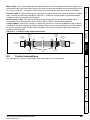
Motor cable: Use a motor cable with an overall shield. Connect the shield of the motor cable to the
ground terminal of the motor frame using a link that is as short as possible and not exceeding 50 mm
(2 in) long. A full 360 ° termination of the shield to the terminal housing of the motor is beneficial.
Encoder cable: For best shielding use cable with an overall shield and individual shields on twisted
pairs, connect the cable as illustrated in Figure 4-6. Clamp the overall shield to grounded metallic
surfaces at both the encoder and the drive.
Brake resistor cable: The optional braking resistor should also be wired with shielded cable. If
unshielded wire is required refer to the Unidrive M700 / M701 User Guide for guidance.
Control cables: If the control wiring is to leave the enclosure, it must be shielded and the shield(s)
clamped to the drive using the grounding bracket. Remove the outer insulating cover of the cable to
ensure the shield(s) make contact with the bracket, but keep the shield(s) intact until as close as
possible to the terminals.
Figure 4-6 Feedback cable shield connections
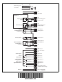
For information on control connections, refer to the back cover of this guide.
Basic parameters
Running the motor
NV Media Card
Operation
Further information
Unidrive M700 Getting Started Guide
Issue Number: 5
29
5
Getting started
This chapter introduces the user interfaces, menu structure and security level of the drive.
5.1
Understanding the display
The keypad can only be mounted on the drive.
5.1.1
SI-Keypad
The SI-Keypad display consists of two rows of text. The upper row shows the drive status or the
menu and parameter number currently being viewed. The lower row of the display line shows the
parameter value or the specific trip type. The last two characters on the first row may display special
indications. If more than one of these indications is active then the indications are prioritized as
shown in Table 5-2.
When the drive is powered up the lower row will show the power up parameter defined by Parameter
Displayed At Power-up (11.022).
Figure 5-1
SI-Keypad
1.
2.
3.
4.
5.
6.
NOTE
Table 5-1
The red stop
Escape button
Start reverse (Auxiliary button)
Start forward
Navigation keys (x4)
Stop / Reset (red) button
Enter button
button is also used to reset the drive.
Active action icon
Active action icon
Description
Priority
Alarm active
Keypad real-time clock battery low
Drive security active
Motor map 2 active
User program running
Motor map 2 and User program running
30
Unidrive M700 Getting Started Guide
Issue Number: 5
Keypad operation
5.2.1
Control buttons
The keypad consists of:
Status
Mode
(Display
not
flashing)
Parameter
Mode
(Upper row
display flashing)
Timeout
or
Press
Timeout
key
Timeout
Electrical installation
To enter Parameter
Mode, press
key or
To return to Status Mode,
Press
key
Getting started
When returning
to Parameter
Mode use the
Temporary
Parameter
Mode
(Upper display
flashing)
To select parameter
Press
Basic parameters
keys to select
another parameter
to change, if
required
To return to Parameter Mode,
Press
key to keep the new parameter value
Press
key to ignore the new parameter value and return
the parameter to the pre-edited value
To enter Edit Mode,
press
key
Running the motor
RO
parameter
R/W
parameter
Edit Mode
(Character to be edited in lower line of display flashing)
Change parameter values using
Mechanical
installation
Navigation Keys - Used to navigate the parameter structure and change parameter values.
Enter / Mode button - Used to toggle between parameter edit and view mode.
Escape / Exit button - Used to exit from parameter edit or view mode. In parameter edit mode, if
parameter values are edited and the exit button pressed the parameter value will be restored to
the value it had on entry to edit mode.
• Start forward button - Use to provide a 'Run' command if keypad mode is selected.
• Start reverse button - Used to control the drive if keypad mode is selected and the reverse button
is activated.
• Stop / Reset button - Used to reset the drive. In keypad mode can be used for 'Stop'.
Figure 5-2 Display modes
Product information
•
•
•
Safety information
5.2
keys.
NV Media Card
Operation
The navigation keys can only be used to move between menus if Pr 00.049 has been set to show 'All
Menus'
Further information
Unidrive M700 Getting Started Guide
Issue Number: 5
31
Figure 5-3
Mode examples
Do not change parameter values without careful consideration; incorrect values may
cause damage or a safety hazard.
WARNING
NOTE
When changing the values of parameters, make a note of the new values in case they
need to be entered again.
NOTE
For new parameter-values to apply after the AC supply to the drive is interrupted, new
values must be saved. Refer to section 5.7 Saving parameters on page 34.
5.3
Menu 0
Menu 0 is used to bring together various commonly used parameters for basic easy set up of the
drive. Appropriate parameters are copied from the advanced menus into menu 0 and thus exist in
both locations. For further information, refer to Chapter 6 Basic parameters (Menu 0) on page 36.
5.4
Menu structure
The drive parameter structure consists of menus and parameters. The drive initially powers up so
that only Menu 0 can be viewed. The up and down arrow buttons are used to navigate between
parameters and once Pr 00.049 has been set to 'All Menus' the left and right buttons are used to
navigate between menus. For further information, refer to section 5.11 Parameter access level and
security on page 35.
Figure 5-4
Menu structure
Menu 41
Menu 0
Menu 1
Menu
2
....MM.000....
41.029
41.028
41.027
41.026
41.025
01.050
01.049
01.048
01.047
01.046
Option module menus (S.mm.ppp)*
00.050
00.049
00.048
00.047
00.046
41.005
41.004
41.003
41.002
41.001
Moves
between
parameters
00.005
00.004
00.003
00.002
00.001
01.005
01.004
01.003
01.002
01.001
The menus and parameters roll over in both
directions. i.e. if the last parameter is
displayed, a further press will cause the
display to rollover and show the first
parameter.
When changing between menus the drive
remembers which parameter was last
viewed in a particular menu and thus
displays that parameter.
* The option module menus (S.mm.ppp) are
only displayed if option modules are
installed. Where S signifies the option
module slot number and the mm.ppp
signifies the menu and the parameter
number of the option module's internal
menus and parameter.
Moves between Menus
32
Unidrive M700 Getting Started Guide
Issue Number: 5
Advanced menus
The advanced menus consist of groups or parameters appropriate to a specific function or feature of
the drive. Menus 0 to 41 can be viewed on the SI-Keypad.
Table 5-2 Advanced menu descriptions
Menu
Commonly used basic set-up parameters for quick / easy programming
Frequency / speed reference
Ramps
Frequency slaving, speed feedback and speed control
Torque and current control
Motor control
Sequencer and clock
Analog I/O
Digital I/O
Programmable logic, motorized pot, binary sum, timers and scope
Status and trips
Drive set-up and identification, serial communications
Threshold detectors and variable selectors
Standard motion control
User PID controller
Option module slot 1 set-up menu
Option module slot 2 set-up menu
Option module slot 3 set-up menu
General option module application menu 1
General option module application menu 2
General option module application menu 3
Second motor parameters
Menu 0 set-up
Not allocated
Ethernet module (slot 4) set-up menu*
Option module slot 1 application parameters
Option module slot 2 application parameters
Option module slot 3 application parameters
Option module slot 4 application parameters
Reserved menu
Onboard user programming application menu
Advanced motion controller setup parameters
Slot 1 option menus**
Slot 2 option menus**
Slot 3 option menus**
Ethernet menus*
Product information
Mechanical
installation
Electrical installation
Getting started
Basic parameters
Running the motor
NV Media Card
Operation
Further information
0
1
2
3
4
5
6
7
8
9
10
11
12
13
14
15
16
17
18
19
20
21
22
23
24
25
26
27
28
29
30
31-41
Slot 1
Slot 2
Slot 3
Slot 4
Description
* Only applicable to Unidrive M700.
** Only displayed when the option modules are installed.
Unidrive M700 Getting Started Guide
Issue Number: 5
Safety information
5.5
33
5.6
Changing the operating mode
Changing the operating mode returns all parameters to their default value, including the motor
parameters. User security status (00.049) and User security code (00.034) are not affected by this
procedure).
Procedure
Use the following procedure only if a different operating mode is required:
1. Ensure the drive is not enabled, i.e. terminal 31 is open or Pr 06.015 is OFF (0)
2. Enter either of the following values in Pr mm.000, as appropriate:
1253 (50Hz AC supply frequency)
1254 (60Hz AC supply frequency)
3. Change the setting of Pr 00.048 as follows:
Pr 00.048 setting
Operating mode
1
Open-loop
(Induction motor)
2
RFC-A
(Induction motor with position feedback)
3
RFC-S
(Permanent magnet motor with position feedback)
The figures in the second column apply when serial communications are used.
4. Either:
• Press the red
reset button
• Toggle the reset digital input
•
Carry out a drive reset through serial communications by setting Pr 10.038 to 100.
NOTE
5.7
Entering 1253 or 1254 in Pr mm.000 will only load defaults if the setting of Pr 00.048 has
been changed.
Saving parameters
When changing a parameter in Menu 0, the new value is saved when pressing the
button to return to parameter view mode from parameter edit mode.
Enter
If parameters have been changed in the advanced menus, then the change will not be saved
automatically. A save function must be carried out.
Procedure
1. Select ‘Save Parameters'* in Pr mm.000 (alternatively enter a value of 1000* in Pr mm.000)
2. Either:
• Press the red
reset button
• Toggle the reset digital input, or
• Carry out a drive reset through serial communications by setting Pr 10.038 to 100
* If the drive is in the under voltage state (i.e. when the control terminal 1 & 2 are being supplied from
a low voltage DC supply) a value of 1001 must be entered into Pr mm.000 to perform a save function.
34
Unidrive M700 Getting Started Guide
Issue Number: 5
Restoring parameter defaults
Restoring parameter defaults by this method saves the default values in the drives memory. User
security status (00.049) and User security code (00.034) are not affected by this procedure).
Procedure
•
•
•
Press the red
reset button
Toggle the reset digital input
Carry out a drive reset through serial communications by setting Pr 10.038 to 100
Displaying parameters with non-default values only
5.10
Displaying destination parameters only
Please note that this function can be affected by the access level enabled, refer to section
5.11 Parameter access level and security on page 35 for further information regarding access level.
5.11
Parameter access level and security
1
All Menus
2
Read-only Menu 0
3
Read-only
4
Status only
5
No access
Open
Closed
Open
Closed
Open
Closed
Open
Closed
Open
Closed
Open
Closed
RW
RO
RW
RO
RO
RO
RO
RO
Not visible
Not visible
Not visible
Not visible
Not visible
Not visible
RW
RO
Not visible
Not visible
RO
RO
Not visible
Not visible
Not visible
Not visible
The default settings of the drive are Parameter Access Level Menu 0 and User Security Open i.e.
read / write access to Menu 0 with the advanced menus not visible.
Unidrive M700 Getting Started Guide
Issue Number: 5
35
Further information
Menu 0
Advanced menu
status
NV Media Card
Operation
0
Menu 0 status
Running the motor
Table 5-3 Parameter access level and security
User security
Access level
User security
status (11.044)
Basic parameters
The parameter access level determines whether the user has access to Menu 0 only or to all the
advanced menus (Menus 1 to 41) in addition to Menu 0. The User Security determines whether the
access to the user is read only or read write. Both the User Security and Parameter Access Level
can operate independently of each other as shown in Table 5-3.
Getting started
By selecting 'Destinations' in Pr mm.000 (Alternatively enter 12001 in Pr mm.000), the only
parameters that will be visible to the user will be destination parameters. This function does not
require a drive reset to become active. In order to deactivate this function, return to Pr mm.000 and
select 'No action' (alternatively enter a value of 0).
Electrical installation
By selecting 'Show non-default' in Pr mm.000 (Alternatively, enter 12000 in Pr mm.000), the only
parameters that will be visible to the user will be those containing a non-default value. This function
does not require a drive reset to become active. In order to deactivate this function, return to
Pr mm.000 and select 'No action' (alternatively enter a value of 0). Please note that this function can
be affected by the access level enabled, refer to section 5.8 Restoring parameter defaults on
page 35 for further information regarding access level.
Mechanical
installation
5.9
Product information
1. Ensure the drive is not enabled, i.e. terminal 31 is open or Pr 06.015 is OFF (0)
2. Select 'Reset 50 Hz Defs' or 'Reset 60 Hz Defs' in Pr mm.000. (alternatively, enter 1233 (50Hz
settings) or 1244 (60Hz settings) in Pr mm.000).
3. Either:
Safety information
5.8
6
Basic parameters (Menu 0)
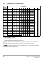
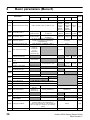
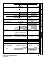
Parameter
00.001 Minimum Reference Clamp
00.002 Maximum Reference Clamp
Range
OL
Default
RFC-A
RFC-S
OL
RFC-A
RFC-S
Type1
±VM_NEGATIVE_REF_CLAMP1 Hz / rpm
0.0 Hz
±VM_POSITIVE_REF_CLAMP Hz / rpm
50Hz
default:
50.0 Hz
60Hz
default:
60.0 Hz
50Hz
default:
1500.0 Hz
60Hz
default:
1800.0 Hz
3000.0
rpm
RW
0.0 rpm
RW
00.003 Acceleration Rate 1
±VM_ACCEL_R
ATE s /100 Hz
±VM_ACCEL_RATE
s /1000 rpm
5.0
s/100 Hz
2.000
s/1000 rpm
0.200
s/1000
RW
00.004 Deceleration Rate 1
±VM_ACCEL_R
ATE s /100 Hz
±VM_ACCEL_RATE
s /1000 rpm
10.0
s/100 Hz
2.000
s/1000 rpm
0.200
s/1000
RW
00.005 Reference Selector
00.006 Symmetrical Current Limit
Open-loop Control Mode
00.007
A1 A2 (0), A1 Preset (1), A2 Preset (2),
Preset (3), Keypad (4), Precision (5),
Keypad Ref (6)
A1 A2 (0)
RW
±VM_MOTOR1_CURRENT_LIMIT %
0.0 %
RW
Ur S (0), Ur (1),
Fixed (2),
Ur Auto (3),
Ur I (4),
Square (5),
Current 1P (6)
Speed Controller
Proportional Gain Kp1
00.008
Low Frequency Voltage
Boost
0.0000 to 200.000 s/rad
0.0 to 25.0 %
Speed Controller Integral
Gain Ki1
Dynamic V to F Select
00.011
Motor Rpm
0.00 to 655.35
Output Frequency
00.013 Torque Producing Current
00.014 Torque Mode Selector
00.015 Ramp Mode Select
±180000 rpm
00.017 Current Reference Filter
Time Constant
00.019 Analog Input 2 Mode
00.020 Analog Input 2 Destination
36
0.0100
s/rad
0.10
s2/rad
1.00
s2/rad
RW
RW
0.00000 1/rad
0 rpm
RW
RW
RW
RW
±VM_SPEED rpm
RO
±VM_SPEED_FREQ_REF Hz
RO
0 to 65535
RO
±VM_DRIVE_CURRENT_UNIPOLAR A
RO
±VM_DRIVE_CURRENT A
RO
0 or 1
0 to 5
0
RW
Fast (0),
Standard (1),
Std boost (2)
Fast (0), Standard (1)
Standard (1)
RW
00.016 Ramp Enable
Digital Input 6 Destination
0.0300
s/rad
OFF (0)
P1 Position
00.012 Current Magnitude
s2/rad
0.00000 to 0.65535 1/rad
Speed Feedback
RW
3.0 %
Off (0) or On (1)
00.009 Speed Controller Differential
Feedback Gain Kd 1
00.010
Ur I (4)
OFF (0) or On (1)
On (1)
RW
0.0 ms
RW
06.031
00.000 to 30.999
0.0 to 25.0 ms
RW
4-20 mA Low (-4), 20-4 mA Low (-3),
4-20 mA Hold (-2), 20-4 mA Hold (-1),
0-20 mA (0), 20-0 mA (1), 4-20 mA Trip (2),
20-4 mA Trip (3), 4-20 mA (4), 20-4 mA (5),
Volt (6)
Volt (6)
RW
00.000 to 30.999
01.037
RW
Unidrive M700 Getting Started Guide
Issue Number: 5
00.021 Analog Input 3 Mode
Range
OL
RFC-S
OL
RFC-A
RFC-S
Type1
Volt (6)
RW
Off (0) or On (1)
OFF(0)
RW
0.0
RW
0.0 to 400.0 Hz
0.0 to 4000.0 rpm
00.024 Preset Reference 1
±VM_SPEED_FREQ_REF rpm
0.0
RW
00.025 Preset Reference 2
±VM_SPEED_FREQ_REF rpm
0.0
RW
00.026
Preset Reference 3
±VM_SPEED_
FREQ_REF Hz
0.0
Overspeed Threshold
Preset Reference 4
±VM_SPEED_
FREQ_REF Hz
RW
1 to 100000
1024
0 to 2
NV Media Card Data
Previously Loaded
RW
0.0
P1 Rotary Lines Per
Revolution
00.028 Enable Auxiliary Key
00.029
0.0
4096
0
RW
RW
0 to 999
RO
00.031 Drive Rated Voltage
200 V (0), 400 V (1), 575 V (2),
690 V (3)
RO
0.000 to 99999.999 A
RO
Disable
(0)
Motor Parameter Adaptive
Control
RW
0 to 2
00.034 User Security Code
RW
0
231-1
RW
00.035 Serial Mode*
8 2 NP (0)
RW
00.036 Serial Baud Rate*
300 (0), 600 (1), 1200 (2), 2400 (3), 4800 (4),
9600 (5), 19200 (6), 38400 (7), 57600 (8),
76800 (9), 115200 (10)
19200 (6)
RW
1 to 247
1
RW
00.037 Serial Address*
00.037 Active IP Address**
000.000.000.000 to 255.255.255.255
00.038 Current Controller Kp Gain
0 to 30000
00.039 Current Controller Ki Gain
00.040 Auto-tune
00.042 Number Of Motor Poles
Rated Power Factor
40
0 to 3
0 to 4
2 kHz (0), 3 kHz (1), 4 kHz (2), 6 kHz (3),
8 kHz (4), 12 kHz (5), 16 kHz (6)
Automatic (0) to 480 Poles (240)
0.000 to 1.000
00.044 Rated Voltage
Unidrive M700 Getting Started Guide
Issue Number: 5
RW
2000
RW
0
RW
3kHz (1)
Automatic (0)
RW
6 Poles
(3)
0.850
0.0 to 359.9 °
±VM_AC_VOLTAGE_SET
RW
RW
RW
200 V drive: 230 V
50 Hz default 400 V drive: 400 V
60 Hz default 400 V drive: 460 V
575 V drive: 575 V
690 V drive: 690 V
RW
37
Further information
00.043 Position Feedback Phase
Angle
150
NV Media Card
Operation
Maximum Switching
00.041
Frequency
0 to 30000
0 to 2
RO
20
Running the motor
RW
0 to
Basic parameters
0
8 2 NP (0), 8 1 NP (1), 8 1 EP (2), 8 1 OP (3),
8 2 NP M (4), 8 1 NP M (5), 8 1 EP M (6),
8 1 OP M (7), 7 2 NP (8), 7 1 NP (9),
7 1 EP (10), 7 1 OP (11), 7 2 NP M (12),
7 1 NP M (13), 7 1 EP M (14), 7 1 OP M (15)
Getting started
Catch A Spinning Motor
00.033
Disable (0),
Enable (1), Fwd
Only (2), Rev
Only (3)
None (0)
Electrical installation
00.030 Parameter copying
None (0), Read (1), Program (2),
Auto (3), Boot (4)
Maximum Heavy Duty
00.032
Rating
Mechanical
installation
00.027
RW
0 to 50000 rpm
Product information
Volt (6), Therm Short Cct (7), Thermistor (8),
Therm No Trip (9)
00.022 Bipolar Reference Enable
00.023 Jog Reference
Default
RFC-A
Safety information
Parameter
Range
Parameter
Rated Speed
00.045
OL
RFC-A
0 to
180000 rpm
0.00 to
50000.00
rpm
Motor Thermal Time
Constant 1
00.046 Rated Current
00.047 Rated Frequency
00.048 Drive Mode
00.049 User Security Status
00.050 Software Version
00.051 Action On Trip Detection
00.052
Reset Serial
Communications*
Default
RFC-S
OL
RFC-A
50Hz
default:
1500 rpm
60Hz
default:
1800rpm
50Hz
default:
1450 rpm
60Hz
default:
1750rpm
1.0 to
3000.0 s
±VM_RATED_CURRENT
0.0 to
3000.0 Hz
0.0 to
1667.0 Hz
Open-loop (1), RFC-A (2),
RFC-S (3), Regen (4)
Menu 0 (0), All Menus (1),
Read-only Menu 0 (2), Read-only (3),
Status Only (4), No Access (5)
RFC-S
RW
89.0 s
Maximum Heavy Duty Rating
(11.032)
50Hz default: 50.0 Hz
60Hz default: 60.0 Hz
Open-loop
(1)
RFC-A
(2)
Type1
RW
RW
RW
RFC-S
(3)
RW
Menu 0 (0)
RW
0 to 31
0
RW
Off (0) or On (1)
Off (0)
RW
0 to 99999999
RO
1
RW = Read Write, RO = Read Only.
* Only applicable to Unidrive M701.
** Only applicable to Unidrive M700.
38
Unidrive M700 Getting Started Guide
Issue Number: 5
Parameter descriptions
6.1.1
Pr mm.000
Safety information
6.1
Product information
Pr mm.000 is available in all menus, commonly used functions are provided as text strings in
Pr mm.000 shown in Table 6-1. The functions in Table 6-1 can also be selected by entering the
appropriate numeric values (as shown in Table 6-2) in Pr mm.000. For example, enter 7001 in
Pr mm.000 to erase the file in NV media card location 001.
Table 6-1 Commonly used functions in Pr mm.000
String
Action
Transfer the drive parameters to parameter file 001
Load file 2
Load the drive parameters or user program file from NV media card file 002
Save to file 2
Transfer the drive parameters to parameter file 002
Load file 3
Load the drive parameters or user program file from NV media card file 003
Save to file 3
Transfer the drive parameters to parameter file 003
Show non-default
Displays parameters that are different from defaults
Destinations
Displays parameters that are set
Reset 50Hz Defs
Load parameters with standard (50 Hz) defaults
Reset 60Hz Defs
Load parameters with US (60 Hz) defaults
Reset modules
Reset all option modules
Read Enc.NP P1
Transfer electronic nameplate motor parameters to the drive from the P1 encoder
Read Enc.NP P2
Transfer electronic nameplate motor parameters to the drive from the P2 encoder
Getting started
Load the drive parameters or user program file from NV media card file 001
Save to file 1
Electrical installation
Load file 1
Mechanical
installation
Save parameters
Save parameters when under voltage is not active and low voltage threshold is not
active
Table 6-2 Functions in Pr mm.000
Action
1000
Save parameters when Under Voltage Active (Pr 10.016) is not active and Low Under Voltage
Threshold Select mode (Pr 06.067 = Off) is not active.
1001
Save parameter under all conditions
1070
Reset all option modules
1233
Load standard (50 Hz) defaults
Basic parameters
Value
Load standard (50 Hz) defaults to all menus except option module menus (i.e 15 to 20 and 24 to 28)
1244
Load US (60 Hz) defaults
1245
Load US (60 Hz) defaults to all menus except option module menus (i.e 15 to 20 and 24 to 28)
1253
Change drive mode and load standard (50 Hz) defaults
1254
Change drive mode and load US (60 Hz) defaults
Change drive mode and load standard (50 Hz) defaults except for menus 15 to 20 and 24 to 28
1256
Change drive mode and load US (60 Hz) defaults except for menus 15 to 20 and 24 to 28
1299
Reset {Stored HF} trip.
2001*
Create a boot file on a non-volatile media card based on the present drive parameters including all
Menu 20 parameters
NV media card: Transfer the drive parameters to parameter file xxx
5yyy*
NV media card: Transfer the onboard user program to onboard user program file xxx
6yyy*
NV media card: Load the drive parameters from parameter file xxx or the onboard user program from
onboard user program file xxx
7yyy*
NV media card: Erase file xxx
Unidrive M700 Getting Started Guide
Issue Number: 5
39
Further information
4yyy*
NV Media Card
Operation
1255
Running the motor
1234
Value
Action
8yyy*
NV Media card: Compare the data in the drive with file xxx
9555*
NV media card: Clear the warning suppression flag
9666*
NV media card: Clear the warning suppression flag
9777*
NV media card: Clear the read-only flag
9888*
NV media card: Set the read-only flag
9999*
NV media card: Erase and format the NV media card
110S0
Transfer electronic nameplate motor object parameters from the drive to an encoder connected to
the drive or an option module.
110S1
Transfer electronic nameplate motor objects parameters from an encoder connected to the drive or
option module to the drive parameters.
110S2
As 110S0, but for performance object 1
110S3
As 110S1, but for performance object 1
110S4
As 110S0, but for performance object 2
110S5
As 110S1, but for performance object 2
110S6
Transfer electronic nameplate motor object parameters from the drive to an encoder connected to
the drive or an option module in the Unidrive SP format.
12000**
Only display parameters that are different from their default value. This action does not require a
drive reset.
12001**
Only display parameters that are used to set-up destinations (i.e. DE format bit is 1). This action does
not require a drive reset.
15xxx*
Transfer the user program in an option module installed in slot 1 to a non-volatile media card file xxx
16xxx*
Transfer the user program in an option module installed in slot 2 to a non-volatile media card file xxx
17xxx*
Transfer the user program in an option module installed in slot 3 to a non-volatile media card file xxx
18xxx*
Transfer the user program from file xxx in a non-volatile media card to an option module installed in slot 1.
19xxx*
Transfer the user program from file xxx in a non-volatile media card to an option module installed in slot 2.
20xxx*
Transfer the user program from file xxx in a non-volatile media card to an option module installed in slot 3.
21xxx*
Transfer the user program in an option module installed in slot 4 to a non-volatile media card file xxx.
22xxx*
Transfer the user program from file xxx in a non-volatile media card to an option module installed in slot 4.
* See section 8 NV Media Card Operation on page 54 for more information on these functions.
** These functions do not require a drive reset to become active. All other functions require a drive
reset to initiate the function.
40
Unidrive M700 Getting Started Guide
Issue Number: 5
Safety information
Product information
Mechanical
installation
Electrical installation
Getting started
Basic parameters
Running the motor
NV Media Card
Operation
Further information
41
Unidrive M700 Getting Started Guide
Issue Number: 5
Figure 6-1
Menu 0 logic diagram
28
29
Analog reference
5
6
Analog
Analog
Input 2
Input 2
Offset Trim Destination
00.013
Analog
Input 2
Mode
7
00.020
+
+
00.019
Any
unprotected
variable
parameter
Analog
??.??
Reference 2
01.037
??.??
01.015
01.050
Pr 01.050
set >1
Bipolar
Reference
Select
00.024
Preset frequency
reference
00.024
Preset
Frequency 1
00.025 Preset
Frequency 2
Open Loop only
00.026
00.027
Preset
Frequency 3
Preset
Frequency 4
Keypad reference
A1.A2
0
A1.Preset 1
A2.Preset 2
Preset
3
Keypad
4
Precision
5
Keypad Ref
6
00.023
Jog Reference
00.028
Enable Forward /
Reverse Key
Precision reference
Key
X
X Input
X
X Output
terminals
terminals
00.XXX
Read-write (RW)
parameter
00.XXX
Read-only (RO)
parameter
The parameters are all shown in their default settings
42
Unidrive M700 Getting Started Guide
Issue Number: 5
26
27
25
9
Safety information
OL> FREQUENCY
TORQUE
RFC-A, RFC-S> SPEED
RUN RUN
FORWARD REVERSE RESET
AT ZERO SPEED
10
24
Analog outputs
Digital output
Product information
Mechanical
installation
Motor control
Maximum
Frequency/
SpeedClamp
00.006 Current
Limit
00.014 Torque Mode
Ramp
Enable
00.002
Selector
OL> Catch A
Spinning Motor
00.033 RFC-A, RFC-S
> Motor Full
RFC-A, Load Rated Speed
RFC-S> Autotune
Current
Demand
00.017
Filter Time
Constant
000.16
00.001
RFC-A, RFC-S modes only
Electrical installation
Minimum
Frequency/
SpeedClamp
RFC-A,
Speed-loop PIDgains
RFC-S>
Speed-Loop
00.007 Proportional
Gain
Getting started
Motor parameters
00.042 ~ 00.047
Number Of Poles
Power Factor
Rated Voltage
Rated Speed
Rated Current
Rated Frequency
SV> Motor Thermal
Time Constant
Ramps
00.003
Acceleration
Rate
00.008
Speed-Loop
Integral Gain
00.015
Speed-Loop
00.009 Derivative
Gain
Motor Speed
00.010
00.007
Voltage Mode
Selector
L1
L2
Drive
L3
00.008
Estimated Boost Voltage
Motor
Speed
00.009
Dynamic V/f
Select
_
+
Power stage
_
+
Basic parameters
Ramp Mode
Selector
RFC-A,
RFC-S
OL>Motor-voltage control
00.004
Deceleration
Rate
00.010
00.027 Drive Encoder
PPR
00.026 Overspeed
Threshold
15 way sub-D
connector
Running the motor
00.041 Maximum Switching
Frequency
00.011 Output Frequency
RFC-A
RFC-S
Torque
Producing
Current
00.013
00.012
Current
Magnitude
U
V
W
_
+
BR
Magnetising
Current
Resistor
optional
NV Media Card
Operation
Further information
Unidrive M700 Getting Started Guide
Issue Number: 5
43
7
Running the motor
This chapter takes the new user through all the essential steps to running a motor for the first time, in
each of the possible operating modes.
Ensure that no damage or safety hazard could arise from the motor starting unexpectedly.
WARNING
CAUTION
CAUTION
The values of the motor parameters affect the protection of the motor.
The default values in the drive should not be relied upon.
It is essential that the correct value is entered in Pr 00.046 Rated Current. This affects the
thermal protection of the motor.
If the drive is started using the keypad it will run to the speed defined by the keypad
reference (Pr 01.017). This may not be acceptable depending on the application. The user
must check in Pr 01.017 and ensure that the keypad reference has been set to 0.
If the intended maximum speed affects the safety of the machinery, additional
independent over-speed protection must be used.
WARNING
7.1
Quick start Connections
7.1.1
Basic requirements
This section shows the basic connections which must be made for the drive to run in the required
mode. For minimal parameter settings to run in each mode please see the relevant part of section
7.2 Quick Start / start-up on page 47.
Table 7-1
Minimum control connection requirements for each control mode
Drive control method
Requirements
Terminal mode
Drive enable
Speed / Torque reference
Run forward / Run reverse
Keypad mode
Drive enable
Communications
Drive enable
Communications link
Table 7-2 Minimum control connection requirements for each mode of operation
Operating mode
Requirements
Open loop mode
Induction motor
RFC-A mode (with position feedback)
Induction motor with position feedback
RFC-S mode (with position feedback)
Permanent magnet motor with position feedback
44
Unidrive M700 Getting Started Guide
Issue Number: 5
!
Braking resistor
(optional)
1
2
2
BR
_
3
0V
Product information
+
+10V
4
Speed
reference
input
5
6
7
8
Communications
port*
Safety information
Figure 7-1 Minimum connections to get the motor running in any operating mode (size 3 and 4)
9
10
AB
AB Servo
A
A\
B
B\
Z
Z\
U
U\
V
V\
W
W\
Cos
Cosref
Sin
Sinref
Data
Data\
A (Cos)
A\ (Cos\)
B (Sin)
B\ (Sin\)
Data
Data\
EnDat
BiSS
SSI
Data
Data\
CLK
CLK\
Freeze
Freeze
T
e
r
m
i
n
a
l
Resolver
21
Cos H
Cos L
Sin H
Sin L
Ref H
Ref L
22
34
24V
23
24
CLK
CLK\
+V
0V
Thermistor Input
5
10
15
25
1
6
11
26
RUN FWD
27
RUN REV
M
o
d
e
28
29
30
L1 L2 L3 U V W
31
SAFE TORQUE OFF
(drive enable)
Induction
motor
U V W
E
Keypad
Optional item, must
be installed
for keypad mode
M
o
d
e
Basic parameters
U V W
Servo motor
(permanent
magnet)
K
e
y
p
a
d
Getting started
Position feedback
connector 15 way D-type
E
Fuses
A A
A A
Z Z 1
B B
U U
V V
W W
Open loop
L1 L2
L3
Marker pulse optional
2
Thermal overload for braking resistor
to protect against fire risk. This must be
wired to interrupt the AC supply in the
event of a fault. This is not required if the
optional internal braking resistor is used
RFC-S
* Ethernet fieldbus communication ports on Unidrive M700 and 485 serial communication ports on
Unidrive M701.
NV Media Card
Operation
RFC-A
Z Z
1
1
Running the motor
B B
Electrical installation
1
2
3
4
5
6
7
8
9
10
11
12
13
14
15
SC EnDat
SC
SC SSI
Hiperface
Mechanical
installation
11
Terminal
Further information
Unidrive M700 Getting Started Guide
Issue Number: 5
45
Figure 7-2 Minimum connections to get the motor running in any operating mode (size 6)
!
Braking resistor
(optional) Size 6 only
1
2
2
3
_
0V
+10V
4
+
BR
Speed
reference
input
5
6
7
8
9
10
11
Communication
ports*
T
e
r
m
i
n
a
l
21
22
24V
23
24
25
5
10
15
1
6
11
26
RUN FWD
27
RUN REV
28
29
Position feedback
connector 15 way D-type
30
L1 L2 L3 U V W
31
SAFE TORQUE OFF
(drive enable)
Induction
motor
U V W
Servo motor
(permanent
magnet)
U V W
E
Keypad
Optional item, must
be installed
for keypad mode
K
e
y
p
a
d
M
o
d
e
E
Fuses
A A
B B
A A
Z Z 1
B B
U U
V V
W W
Open loop
RFC-A
M
o
d
e
Z Z
1
L1 L2
L3
1
Marker pulse optional
2
Thermal overload for braking resistor
to protect against fire risk. This must be
wired to interrupt the AC supply in the
event of a fault. This is not required if the
optional internal braking resistor is used
RFC-S
* Ethernet fieldbus communication ports on Unidrive M700 and 485 serial communication ports on
Unidrive M701.
46
Unidrive M700 Getting Started Guide
Issue Number: 5
Quick Start / start-up
7.2.1
Open loop
Detail
Power-up
the drive
Verify that Open Loop mode is displayed as the drive powers up. If
the mode is incorrect see section 5.6 Changing the operating
mode on page 34.
Ensure:
•
Drive displays ‘Inhibit’
Enter:
•
Motor rated frequency in Pr 00.047 (Hz)
•
Motor rated current in Pr 00.046 (A)
•
Motor rated speed in Pr 00.045 (rpm)
Motor rated voltage in Pr 00.044 (V) - check if
connection
Mot X XXXXXXXXX
No XXXXXXXXXX kg
IP55
or
Set
maximum
frequency
Enter:
•
Maximum frequency in Pr 00.002 (Hz)
Set accel. /
decel. rates
Enter:
•
Acceleration rate in Pr 00.003 (s /100 Hz)
•
Deceleration rate in Pr 00.004 (s /100 Hz) (If braking resistor
installed, set Pr 00.015 = FAST. Also ensure Pr 10.030,
Pr 10.031 and Pr 10.061 are set correctly, otherwise premature
‘Brake R Too Hot’ trips may be seen).
A
8.50
4.90
8.50
4.90
CTP- VEN 1PHASE 1=0,46A P=110W R.F 32MN
0.02
t
100Hz
0.03
0.04
t
Basic parameters
At factory default, terminal 8 is set-up for an analog voltage input. If
a thermistor is connected to terminal 8, then the Analog Input 3
Mode (07.015) parameter must be set to Thermistor Short Cct (7),
Thermistor (8) or Therm No Trip (9).
The thermistor input will be disabled until Pr 07.015 is set to
NOTE
one of the above.
Getting started
Motor
thermistor
set-up
I.cl F °C 40 s S1
-1
V
Hz min kW cosφ
230 50 1445 2.20 0.80
400
CN = 14.5Nm
240 50 1445 2.20 0.76
415
CN = 14.4Nm
Electrical installation
•
Mechanical
installation
Enter motor
nameplate
details
Product information
Before
power-up
Ensure:
•
The drive enable signal is not given (terminal 31)
•
Run signal is not given
•
Motor is connected
I.E.C 34 1(87)
Action
Safety information
7.2
Running the motor
NV Media Card
Operation
Further information
Unidrive M700 Getting Started Guide
Issue Number: 5
47
Action
Detail
The drive is able to perform either a stationary or a rotating autotune. The motor must be at a standstill before an auto-tune is
enabled. A rotating auto-tune should be used whenever possible so
the measured value of power factor of the motor is used by the drive
WARNING
•
Autotune
•
A rotating auto-tune will cause the motor to accelerate
up to 2/3 base speed in the direction selected regardless
of the reference provided. Once complete the motor will
coast to a stop. The enable signal must be removed
before the drive can be made to run at the required
reference.
The drive can be stopped at any time by removing the
run signal or removing the drive enable.
A stationary auto-tune can be used when the motor is loaded
and it is not possible to uncouple the load from the motor shaft.
A stationary auto-tune measures the stator resistance of the
motor and the voltage offset in the drive. These are required for
good performance in vector control modes. A stationary autotune does not measure the power factor of the motor so the
value on the motor nameplate must be entered into Pr 00.043.
A rotating auto-tune should only be used if the motor is
uncoupled. A rotating auto-tune first performs a stationary auto-
cos ∅
RS
σLS
tune before rotating the motor at 2/3 base speed in the direction
selected. The rotating auto-tune measures the power factor of
the motor.
To perform an auto-tune:
•
Set Pr 00.040 = 1 for a stationary auto-tune or set Pr 00.040 = 2
for a rotating auto-tune
•
Close the Drive Enable signal (terminal 31). The drive will
display ’Ready’.
•
Close the run signal (terminal 26 or 27). The lower display will
flash ’Autotune’ while the drive is performing the auto-tune.
•
Wait for the drive to display ’Ready’ or ‘Inhibit’ and for the motor
to come to a standstill.
•
Remove the drive enable and run signal from the drive.
Save
parameters
Run
48
Select 'Save Parameters' in Pr mm.000 (alternatively enter a value
of 1000 in Pr mm.000) and press red
the reset digital input.
reset button or toggle
Drive is now ready to run
Unidrive M700 Getting Started Guide
Issue Number: 5
RFC-A mode (with position feedback)
Induction motor with position feedback
For simplicity only an incremental quadrature encoder will be considered here. For information on
setting up one of the other supported speed feedback devices, refer to Setting up a feedback device
in the Unidrive M700 / M701 User Guide.
Before
power-up
Detail
Ensure:
•
Drive Enable signal is not given (terminal 31)
•
Run signal is not given
•
Motor and feedback device are connected
•
Verify that RFC-A mode is displayed as the drive powers up. If the
mode is incorrect see section section 5.6 Changing the operating
mode on page 34.
Mechanical
installation
Power-up
the drive
Product information
Action
Ensure:
•
Drive displays ‘Inhibit’
Electrical installation
Incremental encoder basic set-up
Enter:
•
Drive encoder type in Pr 03.038 = AB (0): Quadrature encoder
•
Encoder power supply in Pr. 03.036 = 5 V (0), 8 V (1) or 15 V (2).
If output voltage from the encoder is >5 V, then the
NOTE
termination resistors must be disabled Pr 03.039 to 0.
Getting started
Set motor
feedback
parameters
Setting the encoder voltage supply too high for the encoder
could result in damage to the feedback device.
CAUTION
•
At factory default, terminal 8 is set-up for an analog voltage input. If a
thermistor is connected to terminal 8, then the Analog Input 3 Mode
(07.015) parameter must be set to Thermistor Short Cct (7), Thermistor
(8) or Therm No Trip (9).
The thermistor input will be disabled until Pr 07.015 is set to
NOTE
one of the above.
Enter:
•
Motor rated frequency in Pr 00.047 (Hz)
•
Motor rated current in Pr 00.046 (A)
•
Motor rated speed in Pr 00.045 (rpm)
Set
maximum
speed
Enter:
•
Maximum speed in Pr 00.002 (rpm)
Unidrive M700 Getting Started Guide
Issue Number: 5
or
connection
I.cl F °C 40 s S1
V
Hz min-1 kW cosφ A
230 50 1445 2.20 0.80 8.50
400
4.90
CN = 14.5Nm
240 50 1445 2.20 0.76 8.50
415
4.90
CN = 14.4Nm
CTP- VEN 1PHASE 1=0,46A P=110W R.F 32MN
I.E.C 34 1(87)
Motor rated voltage in Pr 00.044 (V) - check if
Mot X XXXXXXXXX
No XXXXXXXXXX kg
IP55
0.02
t
49
Further information
•
NV Media Card
Operation
Enter motor
nameplate
details
Running the motor
Motor
thermistor
set-up
Drive encoder Lines Per Revolution (LPR) in Pr 03.034 (set
according to encoder)
Drive encoder termination resistor setting in Pr 03.039:
0 = A-A\, B-B\, Z-Z\ termination resistors disabled
1 = A-A\, B-B\, termination resistors enabled, Z-Z\ termination
resistors disabled
2 = A-A\, B-B\, Z-Z\ termination resistors enabled
Basic parameters
•
Safety information
7.2.2
Action
Set
acceleration
/
deceleration
rates
Detail
Enter:
•
Acceleration rate in Pr 00.003 (s/1000 rpm)
•
Deceleration rate in Pr 00.004 (s/1000 rpm) (If braking resistor
installed, set Pr 00.015 = FAST. Also ensure Pr 10.030, Pr 10.031
and Pr 10.061 are set correctly, otherwise premature ‘Brake R Too
Hot’ trips may be seen).
1000rpm
0.03
0.04
t
The drive is able to perform either a stationary or a rotating auto-tune.
The motor must be at a standstill before an auto-tune is enabled. A
stationary auto-tune will give moderate performance whereas a rotating
auto-tune will give improved performance as it measures the actual
values of the motor parameters required by the drive.
WARNING
•
Autotune
•
A rotating auto-tune will cause the motor to accelerate up to
2/ base speed in the direction selected regardless of the
3
reference provided. Once complete the motor will coast to a
stop. The enable signal must be removed before the drive
can be made to run at the required reference.
The drive can be stopped at any time by removing the run
signal or removing the drive enable.
A stationary auto-tune can be used when the motor is loaded and it
is not possible to uncouple the load from the motor shaft. The
stationary auto-tune measures the stator resistance and transient
inductance of the motor. These are used to calculate the current
loop gains, and at the end of the test the values in Pr 00.038 and Pr
00.039 are updated. A stationary auto-tune does not measure the
power factor of the motor so the value on the motor nameplate must
be entered into Pr 00.043.
A rotating auto-tune should only be used if the motor is uncoupled.
A rotating auto-tune first performs a stationary auto-tune before
2/
3
base speed in the direction selected. The
rotating the motor at
rotating auto-tune measures the stator inductance of the motor and
calculates the power factor.
To perform an auto-tune:
•
Set Pr 00.040 = 1 for a stationary auto-tune or set Pr 00.040 = 2 for
a rotating auto-tune
•
Close the drive enable signal (terminal 31). The drive will display
’Ready’.
•
Close the run signal (terminal 26 or 27). The lower display will flash
‘Autotune’ while the drive is performing the auto-tune.
•
Wait for the drive to display ’Ready’ or ‘Inhibit’ and for the motor to
come to a standstill
•
Remove the drive enable and run signal from the drive.
Save
parameters
Run
50
cos ∅
RS
σLS
LS
T
Nm
saturation
breakpoints
N rpm
Select 'Save Parameters' in Pr mm.000 (alternatively enter a value of
1000 in Pr mm.000) and press red
digital input.
reset button or toggle the reset
Drive is now ready to run
Unidrive M700 Getting Started Guide
Issue Number: 5
RFC-S mode (with position feedback)
Safety information
7.2.3
Permanent magnet motor with a position feedback
For simplicity only an incremental quadrature encoder with commutation outputs will be considered
here. For information on setting up one of the other supported speed feedback devices, refer to
Setting up a feedback device in the Unidrive M700 / M701 User Guide.
Before
power-up
Detail
Product information
Action
Ensure:
•
The drive enable signal is not given (terminal 31)
•
Run signal is not given
•
Motor and feedback device are connected
Mechanical
installation
Verify that RFC-S mode is displayed as the drive powers up. If the mode
Power-up the is incorrect see section 5.6 Changing the operating mode on page 34.
drive
Ensure:
•
Drive displays ‘inhibit’
Getting started
Set motor
feedback
parameters
Electrical installation
Incremental encoder basic set-up
Enter:
•
Drive encoder type in Pr. 03.038 = AB Servo (3): Quadrature
encoder with commutation outputs
•
Encoder power supply in Pr. 03.036 = 5 V (0), 8 V (1) or 15 V (2).
If output voltage from the encoder is >5 V, then the termination
NOTE
resistors must be disabled Pr 03.039 to 0.
Setting the encoder voltage supply too high for the encoder
could result in damage to the feedback device
CAUTION
•
Enter:
•
Motor rated current in Pr 00.046 (A)
Ensure that this equal to or less than the Heavy Duty rating of the
drive otherwise ‘Motor Too Hot’ trips may occur during the auto-tune.
•
Number of poles in Pr 00.042
•
Motor rated voltage in Pr 00.044 (V)
Enter:
•
Maximum speed in Pr 00.002 (rpm)
Unidrive M700 Getting Started Guide
Issue Number: 5
Model No: 95UXXXXXXXXXXXX
Brake: 12Nm
Volts: 380/480
24V
Cont: 7.7Nm:4.81Arms
0.67A
Stall: 9.5Nm:5.91Arms
Speed: 3000rpm Poles:6
Control Techniques
Kt:
1.6Nm/Arms
Dynamics Ltd
Ins Class: H
ANDOVER, HANTS.
ENGLAND. SP10 5AB
Serial No: XXXXXXXXXXX
0.02
t
51
Further information
Set
maximum
speed
NV Media Card
Operation
Enter motor
nameplate
details
Running the motor
Motor
thermistor
set-up
At factory default, terminal 8 is set-up for an analog voltage input. If a
thermistor is connected to terminal 8, then the Analog Input 3 Mode
(07.015) parameter must be set to Thermistor Short Cct (7), Thermistor
(8) or Therm No Trip (9).
The thermistor input will be disabled until Pr 07.015 is set to
NOTE
one of the above.
Basic parameters
•
Drive encoder Pulses Per Revolution in Pr 03.034 (set according to
encoder)
Drive encoder termination resistor setting in Pr 03.039:
0 = A-A\, B-B\, Z-Z\ termination resistors disabled
1 = A-A\, B-B\, termination resistors enabled, Z-Z\ termination
resistors disabled
2 = A-A\, B-B\, Z-Z\ termination resistors enabled
Action
Detail
Enter:
Set
•
Acceleration rate in Pr 00.003 (s/1000 rpm)
acceleration / •
Deceleration rate in Pr 00.004 (s/1000 rpm) (If braking resistor
deceleration
installed, set Pr 00.015 = Fast. Also ensure Pr 10.030, Pr 10.031 and
rates
Pr 10.061 are set correctly, otherwise premature ‘Brake R Too Hot’
trips may be seen).
1000rpm
0.03
t
0.04
The drive is able to perform either a stationary or a rotating auto-tune.
The motor must be at a standstill before an auto-tune is enabled. A
stationary auto-tune will give moderate performance whereas a rotating
auto-tune will give improved performance as it measures the actual
values of the motor parameters required by the drive.The drive is able to
perform a stationary, rotating, mechanical load measurement or locked
rotor test auto-tune. The motor must be at a standstill before an auto-tune
is enabled. It is suggested that a rotating auto tune is used for accurate
measurement for position feedback phase angle.
•
Autotune
•
A stationary auto-tune can be used when the motor is loaded and it is
not possible to uncouple the load from the motor shaft. A stationary
auto-tune is performed to locate the flux axis of the motor. The
stationary auto-tune measures the stator resistance, inductance in
flux axis, voltage offset at zero current, maximum voltage offset,
inductance in torque axis with no load on the motor and current at
maximum voltage offset of the motor. These are used to calculate the
current loop gains, and at the end of the test the values in Pr 00.038
and Pr 00.039 are updated. If Sensorless mode is not selected then
Position Feedback Phase Angle (03.025) is set-up for the selected
position feedback.
A rotating auto-tune should only be used if the motor is uncoupled.
The rotating auto-tune will rotate the motor by up to 2 mechanical
revolutions in the direction selected, regardless of the reference
provided to obtain the position feedback phase angle. A stationary
auto-tune is then performed to obtain stator resistance, inductance in
flux axis, voltage offset at zero current, maximum voltage offset,
inductance in torque axis with no load on the motor and current at
maximum voltage offset of the motor. From the above obtained
parameters the current loop gains are calculated, and at the end of
the test the values in Pr 00.038 and Pr 00.039 are updated.
WARNING
52
0
0
The rotating auto-tune will rotate the motor by up to 2
mechanical revolutions in the direction selected, regardless of
the reference provided. After a short delay, the motor is further
rotated through a electrical revolution. The enable signal must
be removed before the drive can be made to run at the
required reference. The drive can be stopped at any time by
removing the run signal or removing the drive enable.
Unidrive M700 Getting Started Guide
Issue Number: 5
Save
parameters
0
Select 'Save Parameters' in Pr mm.000 (alternatively enter a value of
1000 in Pr mm.000) and press red
reset digital input.
reset button or toggle the
Mechanical
installation
Run
0
Product information
Autotune
(cont)
Detail
To perform an auto-tune:
•
Set Pr 00.040 = 1 for a stationary auto-tune, Pr 00.040 = 2 for a
rotating auto-tune.
•
Close the run signal (terminal 26 or 27).
•
Close the drive enable signal (terminal 31). The lower display will
flash 'Autotune' while the drive is performing the test.
•
Wait for the drive to display 'Ready' or 'Inhibit' and for the motor to
come to a standstill.
If the drive trips it cannot be reset until the drive enable signal (terminal
31) has been removed.
•
Remove the drive enabled and run signal from the drive.
Safety information
Action
Drive is now ready to run
Electrical installation
Getting started
Basic parameters
Running the motor
NV Media Card
Operation
Further information
Unidrive M700 Getting Started Guide
Issue Number: 5
53
8
NV Media Card Operation
8.1
Introduction
The Non-Volatile Media Card feature enables simple configuration of parameters, parameter back-up
and drive cloning using a SMARTCARD or SD card in the future. The drive offers backward
compatibility for a Unidrive SP SMARTCARD.
The SMARTCARD can be used for:
•
•
Parameter copying between drives
Saving drive parameter sets
The NV Media Card (SMARTCARD) is located at the top of the module under the drive display (if
installed) on the left-hand side.
Ensure the SMARTCARD is inserted with the contacts facing the right-hand side of the drive.
The drive only communicates with the NV Media Card when commanded to read or write, meaning
the card may be "hot swapped".
Be aware of possible live terminals when inserting or removing the SMARTCARD
WARNING
Figure 8-1
Installation of the SMARTCARD
1. Installing the SMARTCARD
2. SMARTCARD installed
54
Unidrive M700 Getting Started Guide
Issue Number: 5
SMARTCARD support
Figure 8-2
Basic SMARTCARD operation
Electrical installation
Programs all drive
parameters to the
SMARTCARD
Drive reads all
parameters from
the SMARTCARD
NOTE
Overwrites any
data already in
data block 1
Boot
Auto
Save
Pr 00.030 = Auto +
Pr 00.030 = Boot +
Transferring data
Data transfer, erasing and protecting the information is performed by entering a code in Pr mm.000
and then resetting the drive as shown in Table 8-1.
Table 8-1 SMARTCARD codes
Code
Where yyy indicates the block number 001 to 999.
Unidrive M700 Getting Started Guide
Issue Number: 5
55
Further information
4001
6yyy
9555
9666
9777
9888
9999
NV Media Card
Operation
2001
Action
Transfer drive parameters as difference from defaults to a bootable SMARTCARD
block in data block number 001
Transfer drive data as difference from defaults to SMARTCARD block number 001
Transfer SMARTCARD data block yyy to the drive
Clear SMARTCARD warning suppression flag
Set SMARTCARD warning suppression flag
Clear SMARTCARD read-only flag
Set SMARTCARD read-only flag
Erase SMARTCARD
Running the motor
8.3
Auto Save
Drive boots from the
SMARTCARD on
power up and
automatically writes
to the SMARTCARD
when a parameter
save is performed
Basic parameters
Drive automatically
writes to the
SMARTCARD
when a parameter
save is performed
Pr 00.030 = Program +
Getting started
Pr 00.030 = Read +
Mechanical
installation
1. If a parameter from the source drive does not exist in the target drive then no data is transferred
for that parameter.
2. If the data for the parameter in the target drive is out of range then the data is limited to the range
of the target parameter.
3. If the target drive has a different rating to the source drive then the normal rules for this type of
transfer apply.
Product information
The SMARTCARD can be used to store one drive parameter set from the Unidrive M in data block
001 on the SMARTCARD. The Unidrive M is compatible with a Unidrive SP SMARTCARD and is
able to read and translate the Unidrive SP parameter set into a compatible parameter set for Unidrive
M. This is only possible if the Unidrive SP parameter set was transferred to the SMARTCARD using
the difference from defaults transfer method (i.e. 4yyy transfer). The Unidrive M is not able to read
any other type of Unidrive SP data block on the card. Although it is possible to transfer difference
from default data blocks from a Unidrive SP into the Unidrive M, the following should be noted:
Safety information
8.2
9
Further information
9.1
Diagnostics
For further information on diagnostics including trips and alarms, refer to the Unidrive
M700 / M701 User Guide.
56
Unidrive M700 Getting Started Guide
Issue Number: 5
1
11
Polarised signal
connectors
41 42
21
31
1
0V
2
+24V input
3
0V
5
Non-inverting input
6
Inverting input
3
0V
5
Non-inverting input
6
Inverting input
4
+10V output
7
Analog input 2
Analog input 3
8
Analog input 3
9
Analog output 1
Speed / frequency
10
Analog output 2
11
0V
21
0V
+24V output
(user selectable)
Analog frequency/speed
reference 1
Single-ended
signal
Differential signal
Analog
frequency/speed
reference 2
Torque (active
current)
22
23
0V
At zero speed
24
Digital I/O 1
Reset
25
Digital I/O 2
Run forward
26
Digital I/O 3
Run reverse
Analog input 1/
input 2 select
27
Digital input 4
28
Digital input 5
29
Digital input 6
30
0V
31
Drive enable (SAFE
TORQUE OFF function)
Jog forward select
Drive ok
Analog input 1
Analog input 2
41
42
0478-0001-05
Relay (Overvoltage
category II)