1
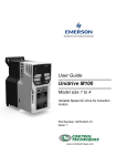
User Guide
Unidrive M200
Model size 1 to 4
Variable Speed AC drive for induction
motors
Part Number: 0478-0042-01
Issue: 1
www.controltechniques.com
Original Instructions
For the purposes of compliance with the EU Machinery Directive 2006/42/EC
General information
The manufacturer accepts no liability for any consequences resulting from inappropriate, negligent or incorrect
installation or adjustment of the optional operating parameters of the equipment or from mismatching the variable speed
drive with the motor.
The contents of this guide are believed to be correct at the time of printing. In the interests of a commitment to a policy
of continuous development and improvement, the manufacturer reserves the right to change the specification of the
product or its performance, or the contents of the guide, without notice.
All rights reserved. No parts of this guide may be reproduced or transmitted in any form or by any means, electrical or
mechanical including photocopying, recording or by an information storage or retrieval system, without permission in
writing from the publisher.
Drive firmware version
This product is supplied with the latest firmware version. If this drive is to be connected to an existing system or machine,
all drive firmware versions should be verified to confirm the same functionality as drives of the same model already
present. This may also apply to drives returned from a Control Techniques Service Centre or Repair Centre. If there is
any doubt please contact the supplier of the product.
The firmware version of the drive can be checked by looking at Pr 11.029.
Environmental statement
Control Techniques is committed to minimising the environmental impacts of its manufacturing operations and of its
products throughout their life cycle. To this end, we operate an Environmental Management System (EMS) which is
certified to the International Standard ISO 14001. Further information on the EMS, our Environmental Policy and other
relevant information is available on request, or can be found at www.greendrives.com.
The electronic variable-speed drives manufactured by Control Techniques have the potential to save energy and
(through increased machine/process efficiency) reduce raw material consumption and scrap throughout their long
working lifetime. In typical applications, these positive environmental effects far outweigh the negative impacts of product
manufacture and end-of-life disposal.
Nevertheless, when the products eventually reach the end of their useful life, they must not be discarded but should
instead be recycled by a specialist recycler of electronic equipment. Recyclers will find the products easy to dismantle
into their major component parts for efficient recycling. Many parts snap together and can be separated without the use
of tools, while other parts are secured with conventional fasteners. Virtually all parts of the product are suitable for
recycling.
Product packaging is of good quality and can be re-used. Large products are packed in wooden crates, while smaller
products come in strong cardboard cartons which themselves have a high recycled fibre content. If not re-used, these
containers can be recycled. Polythene, used on the protective film and bags for wrapping product, can be recycled in the
same way. Control Techniques' packaging strategy prefers easily-recyclable materials of low environmental impact, and
regular reviews identify opportunities for improvement.
When preparing to recycle or dispose of any product or packaging, please observe local legislation and best practice.
REACH legislation
EC Regulation 1907/2006 on the Registration, Evaluation, Authorisation and restriction of Chemicals (REACH) requires
the supplier of an article to inform the recipient if it contains more than a specified proportion of any substance which is
considered by the European Chemicals Agency (ECHA) to be a Substance of Very High Concern (SVHC) and is
therefore listed by them as a candidate for compulsory authorisation.
For current information on how this requirement applies in relation to specific Control Techniques products, please
approach your usual contact in the first instance. Control Techniques position statement can be viewed at:
http://www.controltechniques.com/REACH
Copyright
© May 2013 Control Techniques Ltd
Issue Number: 1
Drive Firmware: 01.01.00.06 onwards
For patent and intellectual property related information please go to: www.ctpatents.info
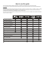
How to use this guide
This user guide provides complete information for installing and operating the drive from start to finish.
The information is in logical order, taking the reader from receiving the drive through to fine tuning the performance.
NOTE
There are specific safety warnings throughout this guide, located in the relevant sections. In addition, Chapter 1 Safety
information contains general safety information. It is essential that the warnings are observed and the information
considered when working with or designing a system using the drive.
This map of the user guide helps to find the right sections for the task you wish to complete, but for specific information,
refer to Contents on page 4:
1 Safety information
2 Product information
3 Mechanical installation
4 Electrical installation
5 Getting started
6 Basic parameters
7 Running the motor
8 Optimization
9 Advanced parameters
10 Technical data
11 Diagnostics
12 UL listing information
Contents
1
Safety information .................................7
5
1.1
1.2
1.3
1.4
1.5
1.6
1.7
1.8
1.9
1.10
1.11
1.12
Warnings, Cautions and Notes .............................7
Electrical safety - general warning ........................7
System design and safety of personnel ................7
Environmental limits ..............................................7
Access ...................................................................7
Fire protection .......................................................7
Compliance with regulations .................................7
Motor .....................................................................7
Mechanical brake control ......................................7
Adjusting parameters ............................................7
Electrical installation ..............................................8
Hazard ...................................................................8
5.1
5.2
5.3
5.4
5.5
5.6
5.7
5.8
5.9
5.10
Getting started .................................... 55
Understanding the display .................................. 55
Keypad operation ............................................... 55
Menu structure ................................................... 57
Menu 0 ............................................................... 57
Advanced menus ............................................... 58
Changing the operating mode ............................ 59
Saving parameters ............................................. 59
Restoring parameter defaults ............................. 59
Parameter access level and security ................. 59
Displaying parameters with non-default
values only ......................................................... 60
5.11 Displaying destination parameters only ............. 60
5.12 Communications ................................................ 60
2
Product information ..............................9
2.1
2.2
2.3
2.4
2.5
2.6
2.7
2.8
Model number .......................................................9
Ratings ................................................................10
Operating modes .................................................13
Drive features ......................................................14
Keypad and display .............................................15
Nameplate description ........................................15
Options ................................................................16
Items supplied with the drive ...............................17
6
Basic parameters ................................ 61
6.1
6.2
Menu 0: Basic parameters ................................. 61
Parameter descriptions ...................................... 66
7
Running the motor .............................. 67
7.1
7.2
7.3
Quick start connections ...................................... 67
Changing the operating mode ............................ 67
Quick start commissioning / start-up .................. 69
3
Mechanical installation .......................18
8
Optimization ........................................ 71
8.1
8.2
8.3
8.4
8.5
Motor map parameters ....................................... 71
Maximum motor rated current ............................ 76
Current limits ...................................................... 76
Motor thermal protection .................................... 76
Switching frequency ........................................... 76
9
Advanced parameters ........................ 78
9.1
9.2
9.3
9.4
9.5
9.6
9.7
9.8
9.9
9.13
9.14
9.15
9.16
9.17
9.18
Menu 1: Frequency reference ............................ 86
Menu 2: Ramps .................................................. 90
Menu 3: Frequency control ................................ 94
Menu 4: Torque and current control ................... 99
Menu 5: Motor control ...................................... 102
Menu 6: Sequencer and clock .......................... 108
Menu 7: Analog I/O .......................................... 111
Menu 8: Digital I/O ........................................... 114
Menu 9: Programmable logic, motorized pot,
binary sum and timers ...................................... 118
Menu 10: Status and trips ................................ 122
Menu 11: General drive set-up ......................... 124
Menu 12: Threshold detectors, variable
selectors and brake control function ................ 126
Menu 14: User PID controller ........................... 132
Menu 15: Option module set-up ....................... 135
Menu 18: Application menu 1 ........................... 136
Menu 20: Application menu 2 ........................... 137
Menu 21: Second motor parameters ................ 138
Menu 22: Additional Menu 0 set-up ................. 139
10
Technical data ................................... 141
3.1
3.2
3.3
3.4
3.5
3.6
3.7
Safety information ...............................................18
Planning the installation ......................................18
Terminal cover removal .......................................19
Installing / removing options ................................20
Dimensions and mounting methods ....................22
Enclosure for standard drives .............................25
Enclosure design and drive ambient
temperature .........................................................27
3.8 Heatsink fan operation ........................................27
3.9 External EMC filter ..............................................28
3.10 Electrical terminals ..............................................30
3.11 Routine maintenance ..........................................31
4
Electrical installation ...........................32
4.1
4.2
4.3
4.4
4.5
4.6
4.7
4.8
4.9
Power connections ..............................................32
AC supply requirements ......................................35
Ratings ................................................................35
Output circuit and motor protection .....................38
Braking ................................................................41
Ground leakage ...................................................43
EMC (Electromagnetic compatibility) ..................43
Communications connections .............................50
Control connections ............................................51
9.10
9.11
9.12
10.1 Drive technical data .......................................... 141
10.2 Optional external EMC filters ........................... 152
4
Unidrive M200 User Guide
Issue Number: 1
11
Diagnostics ........................................154
11.1
11.2
11.3
11.4
11.5
11.6
11.7
11.8
11.9
Status modes ...................................................154
Trip indications ..................................................154
Identifying a trip / trip source .............................154
Trips, Sub-trip numbers ....................................155
Internal / Hardware trips ....................................173
Alarm indications ...............................................173
Status indications ..............................................174
Displaying the trip history ..................................174
Behaviour of the drive when tripped .................174
12
UL Listing ...........................................175
Unidrive M200 User Guide
Issue Number: 1
5
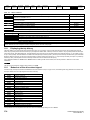
Declaration of Conformity
Control Techniques Ltd
The Gro
Newtown
Powys
UK
SY16 3BE
This declaration applies to Unidrive M variable speed drive products,
comprising models numbers as shown below:
Maaa-bbcddddd Valid characters:
aaa
200, 201
bb
02, 03
c
ddddd
These products comply with the Low Voltage Directive 2006/95/EC and
the Electromagnetic Compatibility Directive 2004/108/EC.
1, 2 or 4
00013, 00018, 00023, 00024, 00032, 00033,
00041, 00042, 00056, 00075
00056, 00073, 00094, 00100
The AC variable speed drive products listed above have been designed
and manufactured in accordance with the following European
harmonized standards:
EN 61800-5-1:2007
Adjustable speed electrical power drive
systems - safety requirements - electrical,
thermal and energy
EN 61800-3:2004
Adjustable speed electrical power drive
systems. EMC product standard including
specific test methods
EN 61000-6-2:2005
Electromagnetic compatibility (EMC). Generic
standards. Immunity standard for industrial
environments
EN 61000-6-4:2007
Electromagnetic compatibility (EMC). Generic
standards. Emission standard for industrial
environments
EN 61000-3-2:2006
Electromagnetic compatibility (EMC), Limits,
Limits for harmonic current emissions
(equipment input current <16 A per phase)
EN 61000-3-3:2008
Electromagnetic compatibility (EMC), Limits,
Limitation of voltage fluctuations and flicker in
low-voltage supply systems for equipment
with rated current <16 A
T. Alexander
Vice President, Technology
Newtown
Date: 11th April 2013
These electronic drive products are intended to be used with
appropriate motors, controllers, electrical protection components
and other equipment to form complete end products or systems.
Compliance with safety and EMC regulations depends upon
installing and configuring drives correctly, including using the
specified input filters. The drives must be installed only by
professional assemblers who are familiar with requirements for
safety and EMC. The assembler is responsible for ensuring that the
end product or system complies with all the relevant laws in the
country where it is to be used. Refer to the User Guide. An EMC
Data Sheet is also available giving detailed EMC information.
EN 61000-3-2:2006 Applicable where input current <16 A. No limits
apply for professional equipment where input power >1 kW.
6
Unidrive M200 User Guide
Issue Number: 1
Safety
information
1
1.1
Product
information
Mechanical
installation
Electrical
installation
Getting
started
Basic
parameters
Advanced
parameters
Technical data
Diagnostics
UL Listing
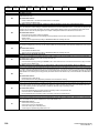
1.6
Warnings, Cautions and Notes
The drive enclosure is not classified as a fire enclosure. A separate fire
enclosure must be provided. For further information, refer to section
3.2.5 Fire protection on page 18.
WARNING
A Caution contains information which is necessary for
avoiding a risk of damage to the product or other equipment.
CAUTION
1.7
Fire protection
Compliance with regulations
The installer is responsible for complying with all relevant regulations,
such as national wiring regulations, accident prevention regulations and
electromagnetic compatibility (EMC) regulations. Particular attention
must be given to the cross-sectional areas of conductors, the selection
of fuses or other protection, and protective ground (earth) connections.
This User Guide contains instruction for achieving compliance with
specific EMC standards.
Within the European Union, all machinery in which this product is used
must comply with the following directives:
NOTE
A Note contains information which helps to ensure correct operation of
the product.
Electrical safety - general warning
The voltages used in the drive can cause severe electrical shock and/or
burns, and could be lethal. Extreme care is necessary at all times when
working with or adjacent to the drive.
Specific warnings are given at the relevant places in this User Guide.
1.3
Optimization
Safety information
A Warning contains information which is essential for
avoiding a safety hazard.
1.2
Running the
motor
System design and safety of
personnel
The drive is intended as a component for professional incorporation into
complete equipment or a system. If installed incorrectly, the drive may
present a safety hazard.
The drive uses high voltages and currents, carries a high level of stored
electrical energy, and is used to control equipment which can cause
injury.
Close attention is required to the electrical installation and the system
design to avoid hazards either in normal operation or in the event of
equipment malfunction. System design, installation, commissioning/
start-up and maintenance must be carried out by personnel who have
the necessary training and experience. They must read this safety
information and this User Guide carefully.
2006/42/EC Safety of machinery.
2004/108/EC: Electromagnetic Compatibility.
1.8
Motor
Ensure the motor is installed in accordance with the manufacturer’s
recommendations. Ensure the motor shaft is not exposed.
Standard squirrel cage induction motors are designed for single speed
operation. If it is intended to use the capability of the drive to run a motor
at speeds above its designed maximum, it is strongly recommended that
the manufacturer is consulted first.
Low speeds may cause the motor to overheat because the cooling fan
becomes less effective. The motor should be installed with a protection
thermistor. If necessary, an electric forced vent fan should be used.
The values of the motor parameters set in the drive affect the protection
of the motor. The default values in the drive should not be relied upon.
It is essential that the correct value is entered in Pr 00.006 motor rated
current. This affects the thermal protection of the motor.
1.9
Mechanical brake control
The STOP functions of the drive do not isolate dangerous voltages from
the output of the drive or from any external option unit. The supply must
be disconnected by an approved electrical isolation device before
gaining access to the electrical connections.
The brake control functions are provided to allow well co-ordinated
operation of an external brake with the drive. While both hardware and
software are designed to high standards of quality and robustness, they
are not intended for use as safety functions, i.e. where a fault or failure
would result in a risk of injury. In any application where the incorrect
operation of the brake release mechanism could result in injury,
independent protection devices of proven integrity must also be
incorporated.
None of the drive functions must be used to ensure safety of
personnel, i.e. they must not be used for safety-related functions.
1.10
Careful consideration must be given to the functions of the drive which
might result in a hazard, either through their intended behavior or
through incorrect operation due to a fault. In any application where a
malfunction of the drive or its control system could lead to or allow
damage, loss or injury, a risk analysis must be carried out, and where
necessary, further measures taken to reduce the risk - for example, an
over-speed protection device in case of failure of the speed control, or a
fail-safe mechanical brake in case of loss of motor braking.
1.4
Adjusting parameters
Some parameters have a profound effect on the operation of the drive.
They must not be altered without careful consideration of the impact on
the controlled system. Measures must be taken to prevent unwanted
changes due to error or tampering.
Environmental limits
Instructions in this User Guide regarding transport, storage, installation
and use of the drive must be complied with, including the specified
environmental limits. Drives must not be subjected to excessive physical
force.
1.5
Access
Drive access must be restricted to authorized personnel only. Safety
regulations which apply at the place of use must be complied with.
Unidrive M200 User Guide
Issue Number: 1
7
Safety
information
Product
information
Mechanical
installation
Electrical
installation
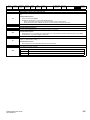
1.11
Electrical installation
1.11.1
Electric shock risk
Getting
started
Basic
parameters
Running the
motor
Optimization
Advanced
parameters
Technical data
Diagnostics
UL Listing
The voltages present in the following locations can cause severe electric
shock and may be lethal:
AC supply cables and connections
Output cables and connections
Many internal parts of the drive, and external option units
Unless otherwise indicated, control terminals are single insulated and
must not be touched.
1.11.2
Stored charge
The drive contains capacitors that remain charged to a potentially lethal
voltage after the AC supply has been disconnected. If the drive has been
energized, the AC supply must be isolated at least ten minutes before
work may continue.
1.12
Hazard
1.12.1
Falling hazard
The drive presents a falling or toppling hazard. This can still cause injury
to personnel and therefore should be handled with care.
Maximum weight:
Size 2: 1.3 kg (3lb).
8
Unidrive M200 User Guide
Issue Number: 1
Safety
information
Product
information
Mechanical
installation
Electrical
installation
Getting
started
2
Product information
2.1
Model number
Basic
parameters
Running the
motor
Optimization
Advanced
parameters
Technical data
Diagnostics
UL listing
information
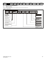
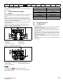
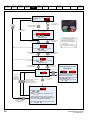
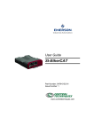
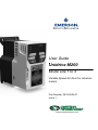
The way in which the model numbers for the Unidrive M range are formed is illustrated below:
Figure 2-1
Model number
Identification Label
Derivative
M200 -
Electrical Specifications
03 4
Unidrive M200
Product Line
00073
A
Reserved
1
0
Optional Build
Documentation Customer Code
1
01
A
B
1
0
0
Reserved:
Conformal Coating:
Frame Size :
0 = Standard
Voltage Rating:
1 - 100 V (100 - 120 ± 10 %)
2 - 200 V (200 - 240 ± 10 %)
4 - 400 V (380 - 480 ± 10 %)
5 - 575 V (500 - 575 ± 10 %)
6 - 690 V (500 - 690 ± 10 %)
Brake Transistor:
B = Brake
Cooling:
Current Rating:
A = Air
Heavy Duty current rating x 10
Customer Code:
Drive Format:
A - AC in AC out
00 = 50 Hz
01 = 60 Hz
Documentation:
0 - Supplied separately
1 - English
Unidrive M200 User Guide
Issue Number: 1
9
Safety
information
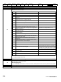
2.2
Product
information
Mechanical
installation
Electrical
installation
Getting
started
Basic
parameters
Running the
motor
Optimization
Advanced
parameters
Technical data
Diagnostics
UL listing
information
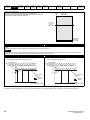
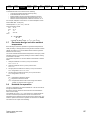
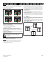
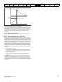
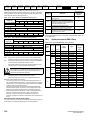
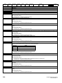
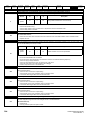
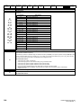
Ratings
The drive is single rated.
The rating is compatible with motors designed to IEC60034.
The graph on the right illustrates Heavy Duty with respect to continuous
current rating and short term overload limits.
Available output
Overload limit current
Heavy Duty
Maximum
continuous
current Heavy Duty
Motor rated
current set
in the drive
Heavy Duty - with high
overload capability
Heavy Duty
For constant torque applications or applications which require a high overload capability, or full torque is required at low speeds (e.g. winders,
hoists).
The thermal protection is set to protect force ventilated induction motors by default.
NOTE
N
If the application uses a self ventilated (TENV/TEFC) induction motor and increased thermal protection is required for speeds below 50 % base
speed, then this can be enabled by setting Low Speed Thermal Protection Mode (04.025) = 1.
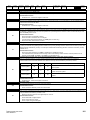
Operation of motor I2t protection
Motor I2t protection is fixed as shown below and is compatible with:
• Self ventilated (TENV/TEFC) induction motors
Motor total
current (Pr 04.001)
as a percentage
of motor rated
current
Motor I2t protection defaults to be compatible with:
• Forced ventilation induction motors
Motor total
current (Pr 04.001)
as a percentage
of motor rated
current
2
I t protection operates in this region
100%
I2t protection operates in this region
100%
70%
70%
15%
50%
100%
Max. permissible
continuous
current
Max. permissible
continuous
current
Pr 04.025 = 0
Pr 04.025 = 1
Pr 04.025 = 0
Pr 04.025 = 1
Motor speed as a
percentage of base speed
50%
100%
Motor speed as a
percentage of base speed
The continuous current ratings given are for maximum 40 °C (104 °F), 1000 m altitude and 3.0 kHz switching. Derating is required for higher switching
frequencies, ambient temperature >40 °C (104 °F) and high altitude. For further information, refer to Chapter 10 Technical data on page 141.
10
Unidrive M200 User Guide
Issue Number: 1
Safety
information
Product
information
Mechanical
installation
Electrical
installation
Getting
started
Basic
parameters
Running the
motor
Optimization
Advanced
parameters
Technical data
Diagnostics
UL listing
information
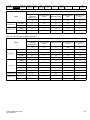
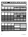
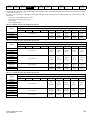
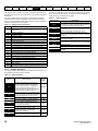
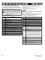
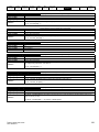
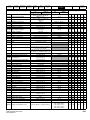
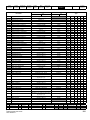
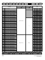
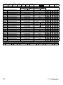
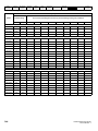
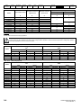
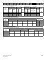
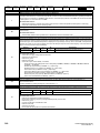
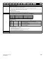
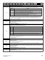
Table 2-1 100 V drive ratings (100 V to 120 V ±10 %)
Heavy Duty
Maximum
continuous
output current
Open loop peak
current
RFC peak current
Nominal power at
100 V
Motor power at
100 V
A
A
A
kW
hp
01100017
1.7
2.6
3.1
0.25
0.33
01100024
2.4
3.6
4.3
0.37
0.5
02100042
4.2
6.3
7.6
0.75
1
02100056
5.6
8.4
10.1
1.1
1.5
Model
Frame size 1
Frame size 2
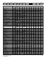
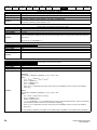
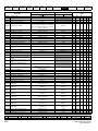
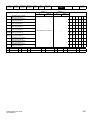
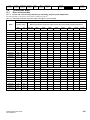
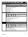
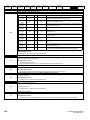
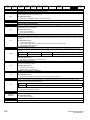
Table 2-2
200 V drive ratings (200 V to 240 V ±10 %)
Heavy Duty
Maximum
continuous
output current
Open loop peak
current
RFC peak current
Nominal power at
230 V
Motor power at
230 V
A
A
A
kW
hp
01200017
1.7
2.6
3.1
0.25
0.33
01200024
2.4
3.6
4.3
0.37
0.5
01200033
3.3
5
5.9
0.55
0.75
01200042
4.2
6.3
7.6
0.75
1
02200024
2.4
3.6
4.3
0.37
0.5
02200033
3.3
5
5.9
0.55
0.75
02200042
4.2
6.3
7.6
0.75
1
02200056
5.6
8.4
10.1
1.1
1.5
02200075
7.5
11.3
13.5
1.5
2
03200100
10.0
15
18.0
2.2
3
04200133
13.3
20
23.9
3
3
04200176
17.6
26.4
31.7
4
5
Model
Frame size 1
Frame size 2
Frame size 3
Frame size 4
Unidrive M200 User Guide
Issue Number: 1
11
Safety
information
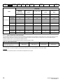
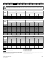
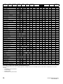
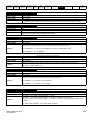
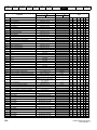
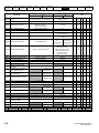
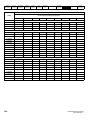
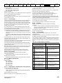
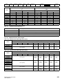
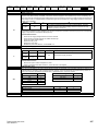
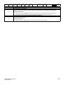
Table 2-3
Product
information
Mechanical
installation
Electrical
installation
Getting
started
Basic
parameters
Running the
motor
Optimization
Advanced
parameters
Technical data
Diagnostics
UL listing
information
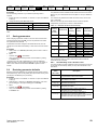
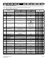
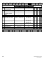
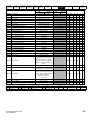
400 V drive ratings (380 V to 480 V ±10 %)
Heavy Duty
Maximum
continuous
output current
Open loop peak
current
RFC peak current
Nominal power at
400 V
Motor power at
400 V
A
A
A
kW
hp
02400013
1.3
2
2.3
0.37
0.5
02400018
1.8
2.7
3.2
0.55
0.75
02400023
2.3
3.5
4.1
0.75
1
02400032
3.2
4.8
5.8
1.1
1.5
02400041
4.1
6.2
7.4
1.5
2
03400056
5.6
8.4
10.1
2.2
3
03400073
7.3
11
13.1
3
3
03400094
9.4
14.1
16.9
4
5
04400135
13.5
20.3
24.3
5.5
7.5
04400170
17.0
25.5
30.6
7.5
10
Model
Frame size 2
Frame size 3
Frame size 4
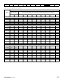
2.2.1
Typical short term overload limits
The maximum percentage overload limit changes depending on the selected motor. Variations in motor rated current, motor power factor and motor
leakage inductance all result in changes in the maximum possible overload. The exact value for a specific motor can be calculated using the
equations detailed in Menu 4 in the Parameter Reference Guide.
Typical values are shown in the table below for RFC-A and open loop (OL) modes:
Table 2-4
Typical overload limits
Operating mode
Heavy Duty overload with motor rated
current = drive rated current
RFC From cold
RFC From 100 %
Open loop from cold
Open loop from 100 %
180 % for 3 s
180 % for 3 s
150 % for 60 s
150 % for 8 s
Generally the drive rated current is higher than the matching motor rated current allowing a higher level of overload than the default setting.
The time allowed in the overload region is proportionally reduced at very low output frequency on some drive ratings.
NOTE
The maximum overload level which can be attained is independent of the speed.
12
Unidrive M200 User Guide
Issue Number: 1
Safety
information
2.3
Product
information
Mechanical
installation
Electrical
installation
Getting
started
Basic
parameters
Running the
motor
Optimization
Advanced
parameters
Technical data
Diagnostics
UL listing
information
Operating modes
The drive is designed to operate in any of the following modes:
1. Open loop mode
Open loop vector mode
Fixed V/F mode (V/Hz)
Square V/F mode (V/Hz)
2. RFC - A
Without position feedback sensor
2.3.1
Open loop mode
The drive applies power to the motor at frequencies varied by the user. The motor speed is a result of the output frequency of the drive and slip due
to the mechanical load. The drive can improve the speed control of the motor by applying slip compensation. The performance at low speed depends
on whether V/F mode or open loop vector mode is selected.
Open loop vector mode
The voltage applied to the motor is directly proportional to the frequency except at low speed where the drive uses motor parameters to apply the
correct voltage to keep the flux constant under varying load conditions.
Typically 100 % torque is available down to 1 Hz for a 50 Hz motor.
Fixed V/F mode
The voltage applied to the motor is directly proportional to the frequency except at low speed where a voltage boost is provided which is set by the
user. This mode can be used for multi-motor applications.
Typically 100 % torque is available down to 4 Hz for a 50 Hz motor.
Square V/F mode
The voltage applied to the motor is directly proportional to the square of the frequency except at low speed where a voltage boost is provided which is
set by the user. This mode can be used for running fan or pump applications with quadratic load characteristics or for multi-motor applications. This
mode is not suitable for applications requiring a high starting torque.
2.3.2
RFC-A mode
Rotor Flux Control for Asynchronous (induction) motors (RFC-A) encompasses closed loop vector control without a position feedback device
Without position feedback sensor
Rotor flux control provides closed loop control without the need for position feedback by using current, voltages and key motor parameters to estimate
the motor speed. It can eliminate instability traditionally associated with open loop control for example when operating large motors with light loads at
low frequencies.
Unidrive M200 User Guide
Issue Number: 1
13
Safety
information
2.4
Product
information
Mechanical
installation
Electrical
installation
Getting
started
Basic
parameters
Running the
motor
Optimization
Advanced
parameters
Technical data
Diagnostics
UL listing
information
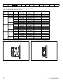
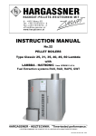
Drive features
Figure 2-2
Features of the drive
2
2
1
3
2
3
1
5
8
5
4
1
7
3
4
6
11
7
11
6
10
8
10
12
12
9
2
2
1
1
3
4
5
4
3
4
5
9
7
3
8
7
8
9
6
11
10
12
6
11
10
12
Key
1. Rating label (On side of drive)
5. Control connections
9. DC bus -
2. Identification label
6. Braking terminal
10. Motor connections
3. Option module
7. Internal EMC filter screw
11. AC supply connections
4. Relay connections
8. DC bus +
12. Ground connections
14
Unidrive M200 User Guide
Issue Number: 1
Safety
information
2.5
Product
information
Mechanical
installation
Electrical
installation
Getting
started
Basic
parameters
Running the
motor
Advanced
parameters
Optimization
Technical data
Diagnostics
UL listing
information
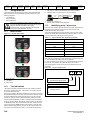
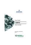
Keypad and display
The keypad and display provide information to the user regarding the operating status of the drive and trip codes, and provide the means for changing
parameters, stopping and starting the drive, and the ability to perform a drive reset.
Figure 2-3
Unidrive M200 keypad detail
Figure 2-4
Unidrive M201 keypad detail
V A Hz rpm %
V A Hz rpm %
6
1
5
2
4
3
1
6
7
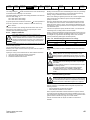
(1) The Enter button is used to enter parameter view or edit mode, or to accept a parameter edit.
(2 / 5) The Navigation keys can be used to select individual parameters or to edit parameter values.
(3) The Stop / Reset key is used to stop and reset the drive in keypad mode. It can also be used to reset the drive in terminal mode.
(4) The Start key is used to start the drive in keypad mode.
(6) The Escape key is used to exit from the parameter edit / view mode.
(7) The Speed Reference Potentiometer is used to control the speed reference in keypad mode (only on Unidrive M201).
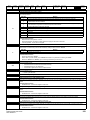
2.6
Nameplate description
See Figure 2-2 for location of rating labels.
Figure 2-5
Typical drive rating labels for size 2
Model number
Key to approvals
CE approval
M200-022 00042 A
Input
voltage
200-240V
0.75kW
V40
Power rating
Refer to
User Guide
R
Europe
C Tick approval
Australia
UL / cUL approval
USA &
Canada
RoHS compliant
Europe
Date code
Model
number
M200-022 00042 A
Input
frequency
Power
rating
75kW
Input voltage
Output
voltage
Date code
No. of phases &
Max input current
Heavy duty
output current
Serial
number
Approvals
Refer to Figure 2-1 Model number on page 9 for further information relating to the labels.
Unidrive M200 User Guide
Issue Number: 1
15
Safety
information
2.7
Product
information
Mechanical
installation
Electrical
installation
Getting
started
Basic
parameters
Running the
motor
Optimization
Advanced
parameters
Technical data
Diagnostics
UL listing
information
Options
Figure 2-6
Options available with the drive
4
1
2
3
1.
2.
3.
4.
16
Adapter Interface (AI) Module
SI module
CT Comms cable
Remote mountable LCD keypad
Unidrive M200 User Guide
Issue Number: 1
Safety
information
Table 2-5
Product
information
Mechanical
installation
Electrical
installation
Getting
started
Basic
parameters
Running the
motor
Optimization
Advanced
parameters
Technical data
Diagnostics
UL listing
information
System Integration Option module identification
Type
Option module
Color
Name
Further Details
Purple
SI-PROFIBUS
Profibus option
PROFIBUS adapter for communications with the drive
Grey
SI-DeviceNet
DeviceNet option
DeviceNet adapter for communications with the drive
Fieldbus
Table 2-6
Adaptor Interface (AI) option module identification
Type
Option module
Communications
2.8
Name
Further Details
AI-485 Adaptor
485 serial communications option
Provides a 485 serial communications interface via an RJ45
connector or alternative screw terminals.
Items supplied with the drive
The drive is supplied with a copy of the Quick Start Guide, a safety information booklet, plus the items shown in Table 2-7.
Table 2-7
Parts supplied with the drive
Description
Size 1
Size 2
Size 3
Size 4
Grounding bracket
M4 x 8 Double Sem Torx screw
x2
Unidrive M200 User Guide
Issue Number: 1
17
Safety
information
3
Product
information
Mechanical
installation
Electrical
installation
Getting
started
Basic
parameters
Running the
motor
Mechanical installation
This chapter describes how to use all mechanical details to install the
drive. The drive is intended to be installed in an enclosure. Key features
of this chapter include:
•
•
•
Enclosure sizing and layout
Option module installing
Terminal location and torque settings
3.1
WARNING
WARNING
WARNING
3.2
Safety information
Follow the instructions
The mechanical and electrical installation instructions must
be adhered to. Any questions or doubt should be referred to
the supplier of the equipment. It is the responsibility of the
owner or user to ensure that the installation of the drive and
any external option unit, and the way in which they are
operated and maintained, comply with the requirements of
the Health and Safety at Work Act in the United Kingdom or
applicable legislation and regulations and codes of practice in
the country in which the equipment is used.
Competence of the installer
The drive must be installed by professional assemblers who
are familiar with the requirements for safety and EMC. The
assembler is responsible for ensuring that the end product or
system complies with all the relevant laws in the country
where it is to be used.
Enclosure
The drive is intended to be mounted in an enclosure which
prevents access except by trained and authorized
personnel, and which prevents the ingress of contamination.
It is designed for use in an environment classified as
pollution degree 2 in accordance with IEC 60664-1. This
means that only dry, non-conducting contamination is
acceptable.
3.2.3
Advanced
parameters
Optimization
Technical data
Diagnostics
UL listing
information
Cooling
The heat produced by the drive must be removed without its specified
operating temperature being exceeded. Note that a sealed enclosure
gives much reduced cooling compared with a ventilated one, and may
need to be larger and/or use internal air circulating fans.
For further information, refer to section 3.6 Enclosure for standard
drives on page 25.
3.2.4
Electrical safety
The installation must be safe under normal and fault conditions.
Electrical installation instructions are given in Chapter 4 Electrical
installation on page 32.
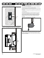
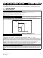
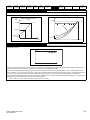
3.2.5
Fire protection
The drive enclosure is not classified as a fire enclosure. A separate fire
enclosure must be provided.
For installation in the USA, a NEMA 12 enclosure is suitable.
For installation outside the USA, the following (based on IEC 62109-1,
standard for PV inverters) is recommended.
Enclosure can be metal and/or polymeric, polymer must meet
requirements which can be summarized for larger enclosures as using
materials meeting at least UL 94 class 5VB at the point of minimum
thickness.
Air filter assemblies to be at least class V-2.
The location and size of the bottom shall cover the area shown in Figure
3-1. Any part of the side which is within the area traced out by the 5°
angle is also considered to be part of the bottom of the fire enclosure.
Figure 3-1
Fire enclosure bottom layout
Drive
Planning the installation
The following considerations must be made when planning the installation:
3.2.1
Access
Access must be restricted to authorized personnel only. Safety
regulations which apply at the place of use must be complied with.
3.2.2
o
5
Environmental protection
The drive must be protected from:
•
•
•
•
•
Moisture, including dripping water or spraying water and
condensation. An anti-condensation heater may be required, which
must be switched off when the drive is running.
Contamination with electrically conductive material
Contamination with any form of dust which may restrict the fan, or
impair airflow over various components
Temperature beyond the specified operating and storage ranges
Corrosive gasses
NOTE
During installation it is recommended that the vents on the drive are
covered to prevent debris (e.g. wire off-cuts) from entering the drive.
o
5
The bottom, including the part of the side considered to be part of the
bottom, must be designed to prevent escape of burning material - either
by having no openings or by having a baffle construction. This means
that openings for cables etc. must be sealed with materials meeting the
5VB requirement, or else have a baffle above. See Figure 3-2 for
acceptable baffle construction. This does not apply for mounting in an
enclosed electrical operating area (restricted access) with concrete floor.
Figure 3-2
Fire enclosure baffle construction
Not less
than 2
times ‘X’
N o t le s s
th a n 2 X
Baffle plates (may be above or
below bottom of enclosure)
B a f f le p la t e s ( m a y b e
a b o v e o r b e lo w b o t t o m
o f e n c lo s u r e )
X
X
B o t t o m o f fir e
e n c lo s u r e
Bottom of fire enclosure
18
Unidrive M200 User Guide
Issue Number: 1
Safety
information
3.2.6
Product
information
Mechanical
installation
Electrical
installation
Getting
started
Basic
parameters
Running the
motor
Optimization
Advanced
parameters
Technical data
Diagnostics
UL listing
information
Electromagnetic compatibility
Variable speed drives are powerful electronic circuits which can cause electromagnetic interference if not installed correctly with careful attention to
the layout of the wiring.
Some simple routine precautions can prevent disturbance to typical industrial control equipment.
If it is necessary to meet strict emission limits, or if it is known that electromagnetically sensitive equipment is located nearby, then full precautions
must be observed. In-built into the drive, is an internal EMC filter, which reduces emissions under certain conditions. If these conditions are exceeded,
then the use of an external EMC filter may be required at the drive inputs, which must be located very close to the drives. Space must be made
available for the filters and allowance made for carefully segregated wiring. Both levels of precautions are covered in section 4.7 EMC
(Electromagnetic compatibility) on page 43.
3.2.7
Hazardous areas
The drive must not be located in a classified hazardous area unless it is installed in an approved enclosure and the installation is certified.
3.3
Terminal cover removal
Isolation device
The AC and / or DC power supply must be disconnected from the drive using an approved isolation device before any cover is removed
from the drive or before any servicing work is performed.
WARNING
Stored charge
The drive contains capacitors that remain charged to a potentially lethal voltage after the AC and / or DC power supply has been
disconnected. If the drive has been energized, the power supply must be isolated at least ten minutes before work may continue.
Normally, the capacitors are discharged by an internal resistor. Under certain, unusual fault conditions, it is possible that the capacitors may
fail to discharge, or be prevented from being discharged by a voltage applied to the output terminals. If the drive has failed in a manner that
causes the display to go blank immediately, it is possible the capacitors will not be discharged. In this case, consult Control Techniques or
their authorized distributor.
WARNING
3.3.1
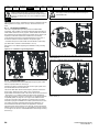
Removing the terminal covers
Figure 3-3
Location and identification of terminal covers
3
4
3
3
2
3
1
Control / AC /
Motor Terminal Cover
Control / AC /
Motor Terminal Cover
Control / AC /
Motor Terminal Cover
Control / AC /
Motor Terminal Cover
NOTE
The drives shown above have a single removable terminal cover which provides access to all electrical connections, i.e. Control, AC, Motor and
Brake functions. Figure 3-4 on page 20 illustrates the three steps required to remove the drive terminal covers.
Unidrive M200 User Guide
Issue Number: 1
19
Safety
information
Figure 3-4
Product
information
Mechanical
installation
Electrical
installation
Getting
started
Basic
parameters
Running the
motor
Optimization
Advanced
parameters
Technical data
Diagnostics
UL listing
information
Removing the terminal cover
1
2
3
1. Using a flat bladed screwdriver, turn the terminal cover locking clip anti-clockwise by approximately 30°
2. Slide the terminal cover down
3. Remove terminal cover
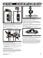
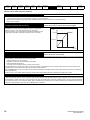
3.4
Installing / removing options
Power down the drive before installing / removing the SI option module. Failure to do so may result in damage to the product.
CAUTION
3.4.1
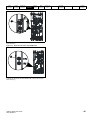
Installation / removal of an SI option module
Figure 3-5
Installation of an SI option module
3
2
1
•
•
With the option module tilted slightly backwards, align and locate the two holes in the rear of the option module onto the two tabs (1) on the drive.
Press the option module onto the drive as shown in (2) until the connector mates with the drive, ensuring that the tab (3) retains the option module
in place.
NOTE
Check that the option module is securely located on the drive. Always ensure that the Terminal Cover is always replaced before use as this ensures
that the option module is firmly secured.
20
Unidrive M200 User Guide
Issue Number: 1
Safety
information
Figure 3-6
Product
information
Mechanical
installation
Electrical
installation
Getting
started
Basic
parameters
Running the
motor
Optimization
Advanced
parameters
Technical data
Diagnostics
UL listing
information
Removal of an SI option module
2
1
•
•
Press down on the tab (1) to release the option module from the drive housing as shown.
Tilt the option module slightly towards you and pull away from the drive housing (2).
3.4.2
Installation / removal of an AI Adaptor
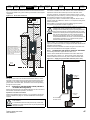
Figure 3-7
Installing the AI-485 Adaptor to the drive
2
1
3
1. Identify the two plastic fingers on the underside of the AI-485 Adaptor (1) - then insert the two fingers into the corresponding slots in the springloaded sliding cover on the top of the drive.
2. Hold the adaptor firmly and push the spring loaded protective cover towards the back of the drive to expose the connector block (2) below.
3. Press the adaptor downwards (3) until the adaptor connector locates into the drive connection below.
Unidrive M200 User Guide
Issue Number: 1
21
Safety
information
Figure 3-8
•
Product
information
Mechanical
installation
Electrical
installation
Getting
started
Basic
parameters
Running the
motor
Optimization
Advanced
parameters
Technical data
Diagnostics
UL listing
information
Removal of the AI-485 Adaptor
To remove the AI-Adaptor, pull it up away from the drive in the direction shown (1)
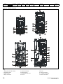
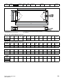
3.5
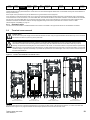
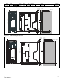
Dimensions and mounting methods
The drive is surface mounted. The following drawings show the dimensions of the drive and mounting holes to allow a back plate to be prepared.
Surface mounting
Figure 3-9
Surface mounting the size 1 drive
137 mm (5.4 in)
75 mm (3.0 in)
53 mm (2.1 in)
Æ5.0 mm
(0.2 in) x 4 holes
143 mm
(5.63 in)
8.0 mm
(0.31 in)
160 mm (6.3 in)
11 mm
(0.43 in)
9.0 mm
(0.35 in)
3.5.1
130 mm (5.12 in)
22
Unidrive M200 User Guide
Issue Number: 1
Safety
information
Figure 3-10
Product
information
Mechanical
installation
Electrical
installation
Getting
started
Basic
parameters
Running the
motor
Advanced
parameters
Optimization
Technical data
Diagnostics
UL listing
information
Surface mounting the size 2 drive
5.5 mm
(0.22 in)
180 mm (7.1 in)
205 mm (8.07 in)
75 mm (3.0 in)
11 mm
(0.43 in)
55 mm (2.20 in)
Æ5.0 mm
(0.2 in) x 4 holes
194 mm
(7.63 in)
5.5 mm
(0.22 in)
150 mm (6.0 in)
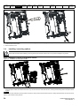
Figure 3-11
Surface mounting the size 3 drive
5.5 mm
(0.21 in)
200 mm (7.9 in)
226 mm (8.9 in)
90 mm (3.54 in)
70 mm (2.76 in)
Æ5.0 mm
(0.2 in) x 4 holes
215 mm
(8.5 in)
160 mm (6.3 in)
Unidrive M200 User Guide
Issue Number: 1
9.5 mm
(0.37 in)
6.0 mm
(0.24 in)
23
Safety
information
Figure 3-12
Product
information
Mechanical
installation
Electrical
installation
Getting
started
Basic
parameters
Running the
motor
Optimization
Advanced
parameters
Technical data
Diagnostics
UL listing
information
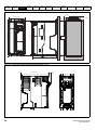
Surface mounting the size 4 drive
14.5 mm
(0.57 in)
6.0 mm
(0.24 in)
245 mm (9.65 in)
86.0 mm (3.40 in)
Æ6.0 mm
(0.24 in) x 4 holes
265 mm
(10.43 in)
6.0 mm
(0.24 in)
277 mm (10.90 in)
115 mm (4.53 in)
175 mm (6.90 in)
Figure 3-13
Size 2 M201 Variant with front panel potentiometer control
150 mm (5.91 in)
24
11 mm
(0.43 in)
Unidrive M200 User Guide
Issue Number: 1
Safety
information
Product
information
Mechanical
installation
Electrical
installation
Getting
started
Basic
parameters
3.6
Enclosure for standard drives
3.6.1
Enclosure layout
Running the
motor
Optimization
Advanced
parameters
Technical data
Diagnostics
UL listing
information
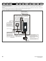
Please observe the clearances in the diagram below taking into account any appropriate notes for other devices / auxiliary equipment when planning
the installation.
Figure 3-14 Enclosure layout
Optional braking resistor and overload
Locate
Locateas
as
required
required
Locate optional braking
resistor external to
cubicle (preferably near to or
on top of the cubicle).
Locate the overload protection
device as required
Enclosure
AC supply
contactor and
fuses or MCB
≥100 mm
(4 in)
Ensure minimum clearances
are maintained for the drive
and external EMC filter. Forced
or convection air-flow must not
be restricted by any object or
cabling
A
The external EMC filter can be
bookcase mounted (next to the
drive) or footprint mounted (with
the drive mounted onto the filter).
≥100 mm
(4 in)
A
A
Size 2: 0 ≥mm (0 in)
Note
For EMC compliance:
1) When using an external EMC
filter, one filter is required for
each drive
2) Power cabling must be at
least 100 mm (4 in) from the
drive in all directions
External
controller
Signal cables
Plan for all signal cables
to be routed at least
300 mm (12 in) from the
drive and any power cable
Unidrive M200 User Guide
Issue Number: 1
25
Safety
information
3.6.2
Product
information
Mechanical
installation
Electrical
installation
Getting
started
Basic
parameters
Enclosure sizing
Running the
motor
Optimization
Figure 3-15
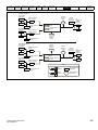
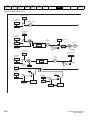
1. Add the dissipation figures from section 10.1.2 Power dissipation on
page 143 for each drive that is to be installed in the enclosure.
2. If an external EMC filter is to be used with each drive, add the
dissipation figures from section 10.2.1 EMC filter ratings on
page 153 for each external EMC filter that is to be installed in the
enclosure.
3. If the braking resistor is to be mounted inside the enclosure, add the
average power figures from for each braking resistor that is to be
installed in the enclosure.
4. Calculate the total heat dissipation (in Watts) of any other equipment
to be installed in the enclosure.
5. Add the heat dissipation figures obtained above. This gives a figure
in Watts for the total heat that will be dissipated inside the enclosure.
Advanced
parameters
Calculate the minimum required unobstructed surface area Ae for the
enclosure from:
P
A e = ----------------------------------k ( Tint – T ext )
Where:
Ae
Unobstructed surface area in m2 (1 m2 = 10.9 ft2)
T
ext
Maximum expected temperature in oC outside the
enclosure
Tint
Maximum permissible temperature in oC inside the
enclosure
Power in Watts dissipated by all heat sources in the
enclosure
Heat transmission coefficient of the enclosure material
P
k
W/m2/oC
in
Example
To calculate the size of an enclosure for the following:
•
•
•
•
•
Two drives operating at the Normal Duty rating
External EMC filter for each drive
Braking resistors are to be mounted outside the enclosure
Maximum ambient temperature inside the enclosure: 40°C
Maximum ambient temperature outside the enclosure: 30°C
For example, if the power dissipation from each drive is 187 W and the
power dissipation from each external EMC filter is 9.2 W.
Total dissipation: 2 x (187 + 9.2) =392.4 W
NOTE
having a heat transmission coefficient of 5.5 W/m2/oC. Only the top,
front, and two sides of the enclosure are free to dissipate heat.
The value of 5.5 W/m2/ºC can generally be used with a sheet steel
enclosure (exact values can be obtained by the supplier of the material).
If in any doubt, allow for a greater margin in the temperature rise.
UL listing
information
H
D
W
Insert the following values:
Tint
40 °C
Text
30 °C
k
5.5
P
392.4 W
The minimum required heat conducting area is then:
392.4
A e = --------------------------------5.5 ( 40 – 30 )
= 7.135 m2 (77.8 ft2) (1 m2 = 10.9 ft2)
Estimate two of the enclosure dimensions - the height (H) and depth (D),
for instance. Calculate the width (W) from:
A e – 2HD
W = -------------------------H+D
Inserting H = 2m and D = 0.6 m, obtain the minimum width:
7.135 – ( 2 × 2 × 0.6 )
W = ----------------------------------------------------2 + 0.6
=1.821 m (71.7 in)
If the enclosure is too large for the space available, it can be made
smaller only by attending to one or all of the following:
•
•
•
•
Using a lower PWM switching frequency to reduce the dissipation in
the drives
Reducing the ambient temperature outside the enclosure, and/or
applying forced-air cooling to the outside of the enclosure
Reducing the number of drives in the enclosure
Removing other heat-generating equipment
Calculating the air-flow in a ventilated enclosure
The dimensions of the enclosure are required only for accommodating
the equipment. The equipment is cooled by the forced air flow.
Calculate the minimum required volume of ventilating air from:
3kP
V = --------------------------T int – T ext
Power dissipation for the drives and the external EMC filters can be
obtained from Chapter 10 Technical data on page 141.
The enclosure is to be made from painted 2 mm (0.079 in) sheet steel
Diagnostics
Enclosure having front, sides and top panels free to
dissipate heat
Calculating the size of a sealed enclosure
The enclosure transfers internally generated heat into the surrounding
air by natural convection (or external forced air flow); the greater the
surface area of the enclosure walls, the better is the dissipation
capability. Only the surfaces of the enclosure that are unobstructed (not
in contact with a wall or floor) can dissipate heat.
Technical data
Where:
V
Text
Tint
P
k
Air-flow in m3 per hour (1 m3/hr = 0.59 ft3/min)
Maximum expected temperature in °C outside the
enclosure
Maximum permissible temperature in °C inside the
enclosure
Power in Watts dissipated by all heat sources in the
enclosure
Po
Ratio of ------Pl
Where:
P0 is the air pressure at sea level
PI is the air pressure at the installation
Typically use a factor of 1.2 to 1.3, to allow also for pressure-drops in
dirty air-filters.
26
Unidrive M200 User Guide
Issue Number: 1
Safety
information
Product
information
Mechanical
installation
Electrical
installation
Getting
started
Basic
parameters
Running the
motor
Optimization
Advanced
parameters
Technical data
Diagnostics
UL listing
information
Example
To calculate the size of an enclosure for the following:
•
•
•
•
•
Three drives operating at the Normal Duty rating
External EMC filter for each drive
Braking resistors are to be mounted outside the enclosure
Maximum ambient temperature inside the enclosure: 40 °C
Maximum ambient temperature outside the enclosure: 30 °C
For example, dissipation of each drive: 101 W and dissipation of each
external EMC filter: 6.9 W (max).
Total dissipation: 3 x (101 + 6.9) = 323.7 W
Insert the following values:
Tint
40 °C
30 °C
Text
k
1.3
P
323.7 W
Then:
3 × 1.3 × 323.7
V = --------------------------------------40 – 30
= 126.2 m3/hr (74.5 ft3 /min) (1 m3/ hr = 0.59 ft3/min)
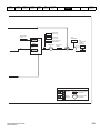
3.7
Enclosure design and drive ambient
temperature
Drive derating is required for operation in high ambient temperatures
Totally enclosing or through panel mounting the drive in either a sealed
cabinet (no airflow) or in a well ventilated cabinet makes a significant
difference on drive cooling.
The chosen method affects the ambient temperature value (Trate) which
should be used for any necessary derating to ensure sufficient cooling
for the whole of the drive.
The ambient temperature for the four different combinations is defined
below:
1. Totally enclosed with no air flow (<2 m/s) over the drive
Trate = Tint + 5 °C
2. Totally enclosed with air flow (>2 m/s) over the drive
Trate = Tint
3. Through panel mounted with no airflow (<2 m/s) over the drive
Trate = the greater of Text +5 °C, or Tint
4. Through panel mounted with air flow (>2 m/s) over the drive
Trate = the greater of Text or Tint
Where:
Text = Temperature outside the cabinet
Tint = Temperature inside the cabinet
Trate = Temperature used to select current rating from tables in
Chapter 10 Technical data on page 141.
3.8
Heatsink fan operation
The drive is ventilated by an internal heatsink fan. The fan channels air
through the heatsink chamber.
Ensure the minimum clearances around the drive are maintained to
allow air to flow freely.
The heatsink fan on size 1, 2, 3, and 4 frames is a variable speed fan.
The drive controls the speed at which the fan runs based on the
temperature of the heatsink and the drive's thermal model system. The
maximum speed at which the fan operates can be limited in Pr 06.045.
This could incur an output current derating.
Unidrive M200 User Guide
Issue Number: 1
27
Safety
information
3.9
Product
information
Mechanical
installation
Electrical
installation
Getting
started
Basic
parameters
Running the
motor
Optimization
Advanced
parameters
Technical data
Diagnostics
UL listing
information
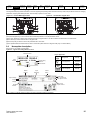
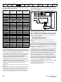
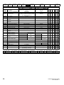
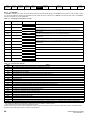
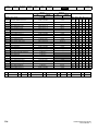
External EMC filter
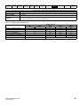
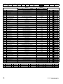
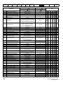
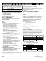
The external EMC filter details for each drive rating are provided in the table below.
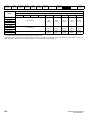
Table 3-1
Frame
size
1
2
Drive and EMC filter cross reference
Voltage
Phases
Part number
Type
Weight
V
1 or 3
All
1
4200-1000
Standard
All
1
4200-1001
Low leakage
100
1
4200-2000
Standard
1
4200-2001
Standard
1
4200-2002
Low leakage
3
4200-2003
Standard
3
4200-2004
Low leakage
3
4200-2005
Standard
3
4200-2006
Low leakage
1
4200-3000
Standard
1
4200-3001
Low leakage
3
4200-3004
Standard
3
4200-3005
Low leakage
3
4200-3008
Standard
3
4200-3009
Low leakage
1
4200-4000
Standard
1
4200-4001
Low leakage
3
4200-4002
Standard
3
4200-4003
Low leakage
3
4200-4004
Standard
3
4200-4005
Low leakage
200
400
200
3
400
200
4
400
Kg
Ib
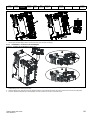
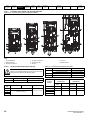
Mount the external EMC filter following the guidelines in section 4.7.5 Compliance with generic emission standards on page 47.
Figure 3-16 Footprint mounting the EMC filter
28
Figure 3-17 Bookcase mounting the EMC filter
Unidrive M200 User Guide
Issue Number: 1
Safety
information
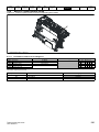
Figure 3-18
Product
information
Mechanical
installation
Electrical
installation
Getting
started
Basic
parameters
Running the
motor
Optimization
Advanced
parameters
Technical data
Diagnostics
UL listing
information
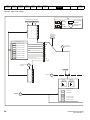
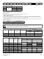
Size 1 to 4 external EMC filter
A
Y
Z
Y
PE U2 V2 W2
X
Last / Load
Netz / Line
C
X
W
U1 V1 W1
V
L1'
L2'
L3'
Z
B
H
D
E
Z
Y
V: Ground stud
X: Threaded holes for footprint mounting of the drive
Z: Bookcase mounting slot diameter.
CS: Cable size
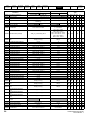
Table 3-2
CT part
number
Table 3-3
CT part
number
Table 3-4
CT part
number
Table 3-5
CT part
number
Y: Footprint mounting hole diameter
Size 1 external EMC filter dimensions
A
B
C
D
E
H
W
V
X
Y
Z
CS
D
E
H
W
V
X
Y
Z
CS
D
E
H
W
V
X
Y
Z
CS
D
E
H
W
V
X
Y
Z
CS
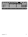
Size 2 external EMC filter dimensions
A
B
C
Size 3 external EMC filter dimensions
A
B
C
Size 4 external EMC filter dimensions
A
Unidrive M200 User Guide
Issue Number: 1
B
C
29
Safety
information
Product
information
Mechanical
installation
Electrical
installation
Getting
started
Basic
parameters
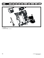
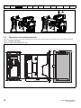
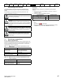
3.10
Electrical terminals
3.10.1
Location of the power and ground terminals
Figure 3-19
Running the
motor
Optimization
Advanced
parameters
Technical data
Diagnostics
UL listing
information
Locations of the power and ground terminals
2
1
1
2
4
5
2
1
4
2
1
4
4
5
5
5
7
3
6
3
8
8
7
6
3
6
6
3
8
7
8
7
Key:
1. Control terminals
4. AC power terminals
7. DC bus +
2. Relay terminals
5. Motor terminals
8. Brake terminal
3. Ground connections
6. DC bus -
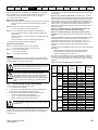
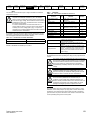
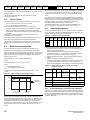
3.10.2
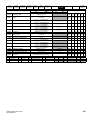
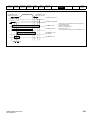
Terminal sizes and torque settings
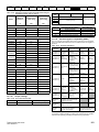
Table 3-8
Terminal block maximum cable sizes
Model size
To avoid a fire hazard and maintain validity of the UL listing,
adhere to the specified tightening torques for the power and
ground terminals. Refer to the following tables.
WARNING
Table 3-6 Drive relay terminal data
Model
Connection type
Torque setting
All
Screw terminals
0.5 N m (0.4 lb ft)
Table 3-7
Model
size
1
Drive power terminal data
AC terminals
DC and braking
Max cable size
Control connector
1.5 mm² (16 AWG)
2 way relay connector
2.5 mm² (12 AWG)
All
AC input power connector
6 mm² (10 AWG)
All
AC output power connector
2.5 mm² (12 AWG)
Table 3-9
CT part
number
External EMC filter terminal data
Power
connections
Max cable
size
Ground
connections
Max torque
Ground
stud size
Max torque
0.5 N m (0.4 lb ft)
2
3
Ground terminal
All
Terminal block description
1.4 N m (1.0 Ib ft)
1.5 N m (1.0 lb ft)
4
30
Unidrive M200 User Guide
Issue Number: 1
Safety
information
3.11
Product
information
Mechanical
installation
Electrical
installation
Getting
started
Basic
parameters
Running the
motor
Optimization
Advanced
parameters
Technical data
Diagnostics
UL listing
information
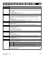
Routine maintenance
The drive should be installed in a cool, clean, well ventilated location. Contact with moisture and/or dust with the drive should be avoided.
Regular checks of the following should be carried out to ensure drive / installation reliability are maximized:
Environment
Ambient temperature
Ensure the enclosure temperature remains at or below maximum specified
Dust
Ensure the drive remains dust free – check that the heatsink and drive fan are not gathering dust.
The lifetime of the fan is reduced in dusty environments
Moisture
Ensure the drive enclosure shows no signs of condensation
Enclosure
Enclosure door filters
Ensure filters are not blocked and that air is free to flow
Electrical
Screw connections
Ensure all screw terminals remain tight
Crimp terminals
Ensure all crimp terminals remains tight – check for any discoloration which could indicate
overheating
Cables
Check all cables for signs of damage
Unidrive M200 User Guide
Issue Number: 1
31
Safety
information
4
Product
information
Mechanical
installation
Electrical
installation
Getting
started
Basic
parameters
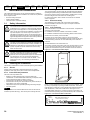
Electrical installation
Many cable management features have been incorporated into the
product and accessories, this chapter shows how to optimize them. Key
features include:
•
•
•
•
Running the
motor
Optimization
Advanced
parameters
Technical data
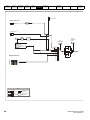
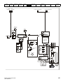
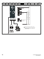
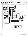
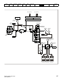
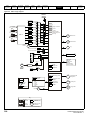
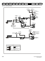
4.1
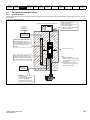
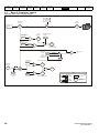
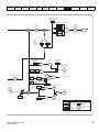
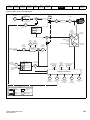
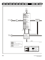
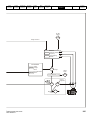
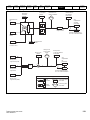
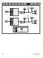
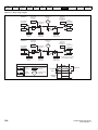
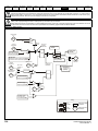
Power connections
4.1.1
AC and DC connections
Figure 4-1
Diagnostics
UL listing
information
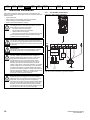
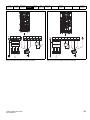
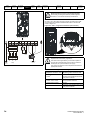
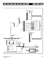
Size 1 power connections
Internal EMC filter
EMC compliance with shielding / grounding accessories
Product rating, fusing and cabling information
Brake resistor details (selection / ratings)
Electric shock risk
The voltages present in the following locations can cause
severe electric shock and may be lethal:
WARNING
WARNING
• AC supply cables and connections
• DC and brake cables, and connections
• Output cables and connections
• Many internal parts of the drive, and external option units
Unless otherwise indicated, control terminals are single
insulated and must not be touched.
Isolation device
The AC and / or DC power supply must be disconnected
from the drive using an approved isolation device before any
cover is removed from the drive or before any servicing work
is performed.
PE
STOP function
The STOP function does not remove dangerous voltages
from the drive, the motor or any external option units.
L
WARNING
WARNING
32
+
BR
U
V
W
Optional EMC
filter
WARNING
Stored charge
The drive contains capacitors that remain charged to a
potentially lethal voltage after the AC and / or DC power
supply has been disconnected. If the drive has been
energized, the AC and / or DC power supply must be
isolated at least ten minutes before work may continue.
Normally, the capacitors are discharged by an internal
resistor. Under certain, unusual fault conditions, it is possible
that the capacitors may fail to discharge, or be prevented
from being discharged by a voltage applied to the output
terminals. If the drive has failed in a manner that causes the
display to go blank immediately, it is possible the capacitors
will not be discharged. In this case, consult Control
Techniques or their authorized distributor.
L2-N
Optional
line reactor
Thermal
overload
protection
device
Fuses
Optional
braking
resistor
Motor
L1
Supply
Ground
L2-N
Mains
Supply
Optional ground
connection
See Figure 4-5 Size 1 to 4 ground connections (size 2 shown) on
page 34 for further information on ground connections.
Equipment supplied by plug and socket
Special attention must be given if the drive is installed in
equipment which is connected to the AC supply by a plug
and socket. The AC supply terminals of the drive are
connected to the internal capacitors through rectifier diodes
which are not intended to give safety isolation. If the plug
terminals can be touched when the plug is disconnected
from the socket, a means of automatically isolating the plug
from the drive must be used (e.g. a latching relay).
Unidrive M200 User Guide
Issue Number: 1
Safety
information
Figure 4-2
PE
L1
Product
information
Mechanical
installation
Electrical
installation
Getting
started
Basic
parameters
Size 2 power connections
L2
L3
U
V
Running the
motor
Optimization
Figure 4-3
W
Optional EMC
filter
-
+
BR
PE
L1
L2
L3
Optional EMC
filter
Diagnostics
UL listing
information
-
+
BR
U
V
W
Thermal
overload
protection
device
Optional
line reactor
Optional
braking
resistor
Fuses
Technical data
Size 3 power connections
Thermal
overload
protection
device
Optional
line reactor
Advanced
parameters
Optional
braking
resistor
Fuses
Internal
EMC
filter
Motor
L1
Supply
Ground
L2
L3
Mains
Supply
L1
Optional ground
connection
See Figure 4-5 Size 1 to 4 ground connections (size 2 shown) on
page 34 for further information on ground connections.
Unidrive M200 User Guide
Issue Number: 1
Motor
Supply
Ground
L2
Mains
Supply
L3
Optional ground
connection
See Figure 4-5 Size 1 to 4 ground connections (size 2 shown) on
page 34 for further information on ground connections.
33
Safety
information
Figure 4-4
Product
information
Mechanical
installation
Electrical
installation
Getting
started
Basic
parameters
Size 4 power connections
Running the
motor
Optimization
4.1.2
Advanced
parameters
Technical data
Diagnostics
UL listing
information
Ground connections
Electrochemical corrosion of grounding terminals
Ensure that grounding terminals are protected against
corrosion i.e. as could be caused by condensation.
WARNING
Size 1 to 4
On sizes 1 to 4, the supply and motor ground connections are made
using the ground connections located at the bottom of the drive as
shown in Figure 4-5.
Figure 4-5
PE
L1
L2
L3
Optional EMC
filter
+
BR
U
V
W
Thermal
overload
protection
device
Optional
line reactor
1
Optional
braking
resistor
Fuses
Internal
EMC
filter
1: 4 x M4 threaded holes for the ground connection.
The ground loop impedance must conform to the
requirements of local safety regulations.
Motor
L1
Supply
Ground
L2
Mains
Supply
Size 1 to 4 ground connections (size 2 shown)
L3
Optional ground
connection
WARNING
The drive must be grounded by a connection capable of
carrying the prospective fault current until the protective
device (fuse, etc.) disconnects the AC supply.
The ground connections must be inspected and tested at
appropriate intervals.
Table 4-1
34
Protective ground cable ratings
Input phase conductor size
Minimum ground conductor size
≤ 10 mm2
Either 10 mm2 or two conductors of
the same cross-sectional area as the
input phase conductor.
> 10 mm2 and ≤ 16 mm2
The same cross-sectional area as the
first input phase conductor.
> 16 mm2 and ≤ 35 mm2
16 mm2
> 35 mm2
Half of the cross-sectional area of the
input phase conductor.
Unidrive M200 User Guide
Issue Number: 1
Safety
information
4.2
Product
information
Mechanical
installation
Electrical
installation
Getting
started
Basic
parameters
AC supply requirements
Voltage:
100 V drive: 100 V to 120 V ±10 %
200 V drive: 200 V to 240 V ±10 %
400 V drive: 380 V to 480 V ±10 %
Number of phases: 3
Maximum supply imbalance: 2 % negative phase sequence (equivalent
to 3 % voltage imbalance between phases).
Frequency range: 48 to 62 Hz
For UL compliance only, the maximum supply symmetrical fault current
must be limited to 100 kA
4.2.1
Supply types
All drives are suitable for use on any supply type i.e TN-S, TN-C-S, TT
and IT.
• Supplies with voltage up to 600 V may have grounding at any
potential, i.e. neutral, centre or corner (“grounded delta”)
• Supplies with voltage above 600 V may not have corner grounding
Drives are suitable for use on supplies of installation category III and
lower, according to IEC60664-1. This means they may be connected
permanently to the supply at its origin in a building, but for outdoor
installation additional over-voltage suppression (transient voltage surge
suppression) must be provided to reduce category IV to category III.
WARNING
Operation with IT (ungrounded) supplies:
Special attention is required when using internal or external
EMC filters with ungrounded supplies, because in the event
of a ground (earth) fault in the motor circuit the drive may not
trip and the filter could be over-stressed. In this case, either
the filter must not be used i.e. removed, or additional
independent motor ground fault protection must be provided.
For instructions on removal, refer to Figure 4-10 Installation
of grounding bracket and Figure 4-13 Removal of the size 3
internal EMC filter . For details of ground fault protection
contact the supplier of the drive.
A ground fault in the supply has no effect in any case. If the motor must
continue to run with a ground fault in its own circuit, then an input
isolating transformer must be provided, and if an EMC filter is required it
must be located in the primary circuit.
Unusual hazards can occur on ungrounded supplies with more than one
source, for example on ships. Contact the supplier of the drive for more
information.
4.2.2
Supplies requiring line reactors
Input line reactors reduce the risk of damage to the drive resulting from
poor phase balance or severe disturbances on the supply network.
Where line reactors are to be used, reactance values of approximately 2
% are recommended. Higher values may be used if necessary, but may
result in a loss of drive output (reduced torque at high speed) because of
the voltage drop.
Running the
motor
Optimization
Advanced
parameters
Technical data
Diagnostics
UL listing
information
Line reactors are particularly recommended for use with the following
drive models when one of the above factors exists, or when the supply
capacity exceeds 175 kVA.
Model sizes 04200133 to 04400170 have an internal DC choke so they
do not require AC line reactors except for cases of excessive phase
unbalance or extreme supply conditions.
When required, each drive must have its own reactor(s). Three individual
reactors or a single three-phase reactor should be used.
Reactor current ratings
The current rating of the line reactors should be as follows:
Continuous current rating:
Not less than the continuous input current rating of the drive
Repetitive peak current rating:
Not less than twice the continuous input current rating of the drive
4.2.3
Input inductor calculation
To calculate the inductance required (at Y%), use the following equation:
Y
V
1
L = ---------- × ------- × -----------100
3 2πfI
Where:
I = drive rated input current (A)
L = inductance (H)
f = supply frequency (Hz)
V = voltage between lines
4.3
Ratings
The input current is affected by the supply voltage and impedance.
Typical input current
The values of typical input current are given to aid calculations for power
flow and power loss.
The values of typical input current are stated for a balanced supply.
Maximum continuous input current
The values of maximum continuous input current are given to aid the
selection of cables and fuses. These values are stated for the worst case
condition with the unusual combination of stiff supply with bad balance.
The value stated for the maximum continuous input current would only
be seen in one of the input phases. The current in the other two phases
would be significantly lower.
The values of maximum input current are stated for a supply with a 2 %
negative phase-sequence imbalance and rated at the supply fault
current given in Table 4-2.
Table 4-2 Supply fault current used to calculate maximum input currents
Model
Symmetrical fault level (kA)
All
100
For all drive ratings, 2 % line reactors permit drives to be used with a
supply unbalance of up to 3.5 % negative phase sequence (equivalent to
5 % voltage imbalance between phases).
Severe disturbances may be caused by the following factors, for example:
•
•
•
Power factor correction equipment connected close to the drive.
Large DC drives having no or inadequate line reactors connected to
the supply.
Across the line (DOL) started motor(s) connected to the supply such
that when any of these motors are started, the voltage dip exceeds
20 %.
Such disturbances may cause excessive peak currents to flow in the
input power circuit of the drive. This may cause nuisance tripping, or in
extreme cases, failure of the drive.
Drives of low power rating may also be susceptible to disturbance when
connected to supplies with a high rated capacity.
Unidrive M200 User Guide
Issue Number: 1
35
Safety
information
Product
information
Mechanical
installation
Electrical
installation
Getting
started
Basic
parameters
Running the
motor
Optimization
Advanced
parameters
Technical data
Diagnostics
UL listing
information
Fuses
WARNING
The AC supply to the drive must be installed with suitable protection against overload and short-circuits. Table 4-3 shows recommended
fuse ratings. Failure to observe this requirement will cause risk of fire.
Table 4-3 AC Input current and fuse ratings (100 V)
Model
Typical input
current
A
Maximum
continuous
input current
A
Fuse rating
Maximum
overload input
current
IEC gG
Class CC or Class J
Maximum
Maximum
A
A
A
10
01100017
8.7
8.7
10
01100024
11.1
11.1
16
16
02100042
18.8
18.8
20
20
02100056
24.0
24.0
25
25
Table 4-4
AC Input current and fuse ratings (200 V)
Fuse rating
Typical input
current
Maximum
overload input
current
A
A
Maximum
continuous
input current
A
01200017
4.5
4.5
01200024
5.3
5.3
01200033
8.3
8.3
10
16
Model
IEC gG
Class CC or Class J
Maximum
A
Maximum
A
1ph
3ph
3ph
5
6
10
01200042
10.4
10.4
02200024
5.3/3.2
5.3/4.1
6
02200033
8.3/4.3
8.3/6.7
10
02200042
10.4/5.4
10.4/7.5
02200056
14.9/7.4
14.9/11.3
02200075
18.1/9.1
18.1/13.5
03200100
23.9/12.8
04200133
23.7/13.5
04200176
17.0
21.3
Table 4-5
1ph
16
10
5
10
16
10
16
10
20
16
20
16
23.9/17.7
25
20
25
20
23.7/16.9
25
20
25
20
25
25
AC Input current and fuse ratings (400 V)
Model
Typical input
current
Maximum
continuous input
current
A
A
02400013
2.1
2.4
02400018
2.6
2.9
02400023
3.1
3.5
Maximum
overload input
current
A
Fuse rating
IEC gG
Class CC or Class J
Maximum
Maximum
A
A
6
02400032
4.7
5.1
02400041
5.8
6.2
10
10
5
10
03400056
8.3
8.7
03400073
10.2
12.2
03400094
13.1
14.8
04400135
14.0
16.3
20
20
04400170
18.5
20.7
25
25
16
10
16
20
NOTE
Ensure cables used suit local wiring regulations.
36
Unidrive M200 User Guide
Issue Number: 1
Safety
information
Product
information
Mechanical
installation
Electrical
installation
Getting
started
Basic
parameters
Running the
motor
Optimization
Advanced
parameters
Technical data
UL listing
information
Diagnostics
The nominal cable sizes below are only a guide. The mounting and grouping of cables affects their current-carrying capacity, in some cases
smaller cables may be acceptable but in other cases a larger cable is required to avoid excessive temperature or voltage drop. Refer to
local wiring regulations for the correct size of cables.
CAUTION
Table 4-6
Cable ratings (100 V)
Cable size (IEC 60364-5-52)
Cable size (UL508C)
AWG
mm2
Model
Input
Nominal
Output
Maximum
Nominal
Input
Maximum
Nominal
Output
Maximum
Nominal
01100017
1
1
16
16
01100024
1.5
1
14
16
02100042
2.5
1
12
16
02100056
4
1
10
16
Table 4-7
Cable ratings (200 V)
Cable size (IEC 60364-5-52)
Cable size (UL 508C)
AWG
mm2
Model
Input
Nominal
Output
Maximum
Nominal
Input
Maximum
Nominal
Output
Maximum
Nominal
01200017
1
1
16
16
01200024
1
1
16
16
01200033
1
1
16
16
01200042
1
1
16
16
02200024
1
1
16
16
02200033
1
1
16
16
02200042
1
1
16
16
02200056
2.5/1.5
1
12/14
16
02200075
2.5
1
12
16
03200100
4
1.5
10/12
14
04200133
4/2.5
2.5
10
12
04200176
4
2.5
10
12
Table 4-8
Maximum
Maximum
Cable ratings (400 V)
Cable size (IEC 60364-5-52)
Cable size (UL 508C)
AWG
mm2
Model
Input
Nominal
Output
Maximum
Nominal
Input
Maximum
Nominal
Output
Maximum
Nominal
02400013
1
1
16
16
02400018
1
1
16
16
02400023
1
1
16
16
02400032
1
1
16
16
02400041
1
1
16
16
03400056
1
1
14
16
03400073
1.5
1
12
16
03400094
2.5
1.5
12
14
04400135
2.5
2.5
10
12
04400170
4
2.5
10
12
NOTE
PVC insulated cable should be used.
NOTE
Cable sizes are from IEC60364-5-52:2001 table A.52.C with correction
factor for 40°C ambient of 0.87 (from table A52.14) for cable installation
method B2 (multicore cable in conduit).
Unidrive M200 User Guide
Issue Number: 1
Maximum
Installation class (ref: IEC60364-5-52:2001)
B1 - Separate cables in conduit.
B2 - Multicore cable in conduit.
C - Multicore cable in free air.
Cable size may be reduced if a different installation method is used, or if
the ambient temperature is lower.
37
Safety
information
NOTE
Product
information
Mechanical
installation
Electrical
installation
Getting
started
Basic
parameters
Running the
motor
Optimization
Advanced
parameters
Technical data
Diagnostics
UL listing
information
N
The nominal output cable sizes assume that the motor maximum current
matches that of the drive. Where a motor of reduced rating is used the
cable rating may be chosen to match that of the motor. To ensure that
the motor and cable are protected against overload, the drive must be
programmed with the correct motor rated current.
A fuse or other protection must be included in all live connections to the
AC supply.
Fuse types
The fuse voltage rating must be suitable for the drive supply voltage.
MCB
Do not use an MCB instead of the recommended fuses.
Ground connections
The drive must be connected to the system ground of the AC supply.
The ground wiring must conform to local regulations and codes of
practice.
NOTE
N
For information on ground cable sizes, refer to Table 4-1 Protective
ground cable ratings on page 34.
4.3.1
Main AC supply contactor
The recommended AC supply contactor type for size 1 to 4 is AC1.
4.4
Output circuit and motor protection
The output circuit has fast-acting electronic short-circuit protection which
limits the fault current to typically no more than 2.5 times the rated output
current, and interrupts the current in approximately 20 µs. No additional
short-circuit protection devices are required.
The drive provides overload protection for the motor and its cable. For
this to be effective, Rated Current (00.006) must be set to suit the motor.
Motor Rated Current (00.006) must be set correctly to avoid
a risk of fire in the event of motor overload.
WARNING
There is also provision for the use of a motor thermistor to prevent overheating of the motor, e.g. due to loss of cooling.
38
Unidrive M200 User Guide
Issue Number: 1
Safety
information
4.4.1
Product
information
Mechanical
installation
Electrical
installation
Getting
started
Basic
parameters
Running the
motor
Optimization
Advanced
parameters
Technical data
Diagnostics
UL listing
information
Cable types and lengths
Since capacitance in the motor cable causes loading on the output of the drive, ensure the cable length does not exceed the values given in Table 49, Table 4-10 and Table 4-11.
Use 105 °C (221 °F) (UL 60/75 °C temp rise) PVC-insulated cable with copper conductors having a suitable voltage rating, for the following power
connections:
•
•
•
•
AC supply to external EMC filter (when used)
AC supply (or external EMC filter) to drive
Drive to motor
Drive to braking resistor
Table 4-9
Maximum motor cable lengths (100 V drives)
100 V Nominal AC supply voltage
Model
Maximum permissible motor cable length for each of the following switching frequencies
0.667 kHz
01100017
01100024
02100042
02100056
Table 4-10
1 kHz
2 kHz
3 kHz
4 kHz
6 kHz
8 kHz
12 kHz
16 kHz
50 m (164 ft)
37.5 m
(123 ft)
25 m
(82 ft)
18.75 m
(61 ft)
12.5 m
(41 ft)
9m
(30 ft)
100 m (328 ft)
75 m
(246 ft)
50 m
(164 ft)
37.5 m
(123 ft)
25 m
(82 ft)
18 m
(59 ft)
Maximum motor cable lengths (200 V drives)
200 V Nominal AC supply voltage
Model
Maximum permissible motor cable length for each of the following switching frequencies
0.667 kHz
1 kHz
2 kHz
3 kHz
4 kHz
6 kHz
8 kHz
12 kHz
16 kHz
50 m (164 ft)
37.5 m
(123 ft)
25 m
(82 ft)
18.75 m
(61 ft)
12.5 m
(41 ft)
9m
(30 ft)
02200024
02200033
02200042
02200056
02200075
100 m (328 ft)
75 m
(246 ft)
50 m
(164 ft)
37.5 m
(123 ft)
25 m
(82 ft)
18 m
(59 ft)
03200100
100 m (328 ft)
75 m
(246 ft)
50 m
(164 ft)
37.5 m
(123 ft)
25 m
(82 ft)
18 m
(59 ft)
04200133
04200176
100 m (328 ft)
75 m
(246 ft)
50 m
(164 ft)
37.5 m
(123 ft)
25 m
(82 ft)
18 m
(59 ft)
01200017
01200024
01200033
01200042
Table 4-11
Maximum motor cable lengths (400 V drives)
400 V Nominal AC supply voltage
Model
Maximum permissible motor cable length for each of the following switching frequencies
0.667 kHz
1 kHz
2 kHz
3 kHz
4 kHz
6 kHz
8 kHz
12 kHz
16 kHz
100 m (328 ft)
75 m
(246 ft)
50 m
(164 ft)
37.5 m
(123 ft)
25 m
(82 ft)
18.25 m
(61 ft)
100 m (328 ft)
75 m
(246 ft)
50 m
(164 ft)
37.5 m
(123 ft)
25 m
(82 ft)
18.25 m
(61 ft)
100 m (328 ft)
75 m
(246 ft)
50 m
(164 ft)
37.5 m
(123 ft)
25 m
(82 ft)
18.25 m
(61 ft)
02400013
02400018
02400023
02400032
02400041
03400056
03400073
03400094
04400135
04400170
Unidrive M200 User Guide
Issue Number: 1
39
Safety
information
Product
information
Mechanical
installation
Electrical
installation
Getting
started
Basic
parameters
4.4.2 High-capacitance / reduced diameter cables
The maximum cable length is reduced from that shown in Table 4-9,
Table 4-10 and Table 4-11, if high capacitance or reduced diameter
motor cables are used.
Most cables have an insulating jacket between the cores and the armor
or shield; these cables have a low capacitance and are recommended.
Cables that do not have an insulating jacket tend to have high
capacitance; if a cable of this type is used, the maximum cable length is
half that quoted in the tables, (Figure 4-6 shows how to identify the two
types).
Figure 4-6
Cable construction influencing the capacitance
Running the
motor
4.4.4
Optimization
Advanced
parameters
Technical data
Diagnostics
UL listing
information
Multiple motors
Open-loop only
If the drive is to control more than one motor, one of the fixed V/F modes
should be selected (Pr 05.014 = Fixed or Squared). Make the motor
connections as shown in Figure 4-7 and Figure 4-8. The maximum cable
lengths in Table 4-9, Table 4-10 and Table 4-11 apply to the sum of the
total cable lengths from the drive to each motor.
It is recommended that each motor is connected through a protection relay
since the drive cannot protect each motor individually. For
connection, a
sinusoidal filter or an output inductor must be connected as shown in
Figure 4-8, even when the cable lengths are less than the maximum
permissible. For details of inductor sizes refer to the supplier of the drive.
Figure 4-7 Preferred chain connection for multiple motors
Motor protection
relay
Normal capacitance
Shield or armour
separated from the cores
High capacitance
Shield or armour close
to the cores
Chain connection (preferred)
The cable used for Table 4-9, Table 4-10 and Table 4-11 is shielded and
contains four cores. Typical capacitance for this type of cable is 130 pF/
m (i.e. from one core to all others and the shield connected together).
4.4.3
Motor winding voltage
The PWM output voltage can adversely affect the inter-turn insulation in
the motor. This is because of the high rate of change of voltage, in
conjunction with the impedance of the motor cable and the distributed
nature of the motor winding.
For normal operation with AC supplies up to 500 Vac and a standard
motor with a good quality insulation system, there is no need for any
special precautions. In case of doubt the motor supplier should be
consulted. Special precautions are recommended under the following
conditions, but only if the motor cable length exceeds 10 m:
•
•
•
•
AC supply voltage exceeds 500 V
DC supply voltage exceeds 670 V
Operation of 400 V drive with continuous or very frequent sustained
braking
Multiple motors connected to a single drive
Figure 4-8
Alternative connection for multiple motors
Motor protection
relay
For multiple motors, the precautions given in section 4.4.4 Multiple
motors on page 40 should be followed.
For the other cases listed, it is recommended that an inverter-rated
motor be used taking into account the voltage rating of the inverter. This
has a reinforced insulation system intended by the manufacturer for
repetitive fast-rising pulsed voltage operation.
Users of 575 V NEMA rated motors should note that the specification for
inverter-rated motors given in NEMA MG1 section 31 is sufficient for
motoring operation but not where the motor spends significant periods
braking. In that case an insulation peak voltage rating of 2.2 kV is
recommended.
connection
Inductor
If it is not practical to use an inverter-rated motor, an output choke
(inductor) should be used. The recommended type is a simple iron-cored
component with a reactance of about 2 %. The exact value is not critical.
This operates in conjunction with the capacitance of the motor cable to
increase the rise-time of the motor terminal voltage and prevent
excessive electrical stress.
40
Unidrive M200 User Guide
Issue Number: 1
Safety
information
4.4.5
Product
information
Mechanical
installation
Electrical
installation
Getting
started
Basic
parameters
/ Δ motor operation
The voltage rating for
and Δ connections of the motor should always
be checked before attempting to run the motor.
The default setting of the motor rated voltage parameter is the same as
the drive rated voltage, i.e.
400 V drive 400 V rated voltage
230 V drive 230 V rated voltage
A typical 3 phase motor would be connected in
for 400 V operation or
Δ for 230 V operation, however, variations on this are common e.g.
690 V Δ 400 V.
Incorrect connection of the windings will cause severe under or over
fluxing of the motor, leading to a very poor output torque or motor
saturation and overheating respectively.
4.4.6
WARNING
Output contactor
If the cable between the drive and the motor is to be
interrupted by a contactor or circuit breaker, ensure that the
drive is disabled before the contactor or circuit breaker is
opened or closed. Severe arcing may occur if this circuit is
interrupted with the motor running at high current and low
speed.
Running the
motor
Optimization
4.5
Switching of an output contactor should only occur when the output of
the drive is disabled.
Technical data
Diagnostics
UL listing
information
Braking
Braking occurs when the drive is decelerating the motor, or is preventing
the motor from gaining speed due to mechanical influences. During
braking, energy is returned to the drive from the motor.
When motor braking is applied by the drive, the maximum regenerated
power that the drive can absorb is equal to the power dissipation
(losses) of the drive.
When the regenerated power is likely to exceed these losses, the DC
bus voltage of the drive increases. Under default conditions, the drive
brakes the motor under PI control, which extends the deceleration time
as necessary in order to prevent the DC bus voltage from rising above a
user defined set-point.
If the drive is expected to rapidly decelerate a load, or to hold back an
overhauling load, a braking resistor must be installed.
Table 4-12 shows the default DC voltage level at which the drive turns on
the braking transistor. However the braking resistor turn on and the turn
off voltages are programmable with Braking IGBT Lower Threshold
(06.073) and Braking IGBT Upper Threshold (06.074).
Table 4-12
Default braking transistor turn on voltage
Drive voltage rating
DC bus voltage level
100 & 200 V
390 V
400 V
780 V
A contactor is sometimes required to be installed between the drive and
motor for safety purposes.
The recommended motor contactor is the AC3 type.
Advanced
parameters
NOTE
N
When a braking resistor is used, Pr 02.004 should be set to Fast ramp
mode.
Opening or closing of the contactor with the drive enabled will lead to:
1. OI ac trips (which cannot be reset for 10 seconds)
2. High levels of radio frequency noise emission
3. Increased contactor wear and tear
WARNING
CAUTION
4.5.1
WARNING
High temperatures
Braking resistors can reach high temperatures. Locate
braking resistors so that damage cannot result. Use cable
having insulation capable of withstanding high temperatures.
Braking resistor overload protection parameter settings
Failure to observe the following information may damage
the resistor.
The drive software contains an overload protection function
for a braking resistor.
For more information on the braking resistor software
overload protection, see Pr 10.030, Pr 10.031 and
Pr 10.061 full descriptions in the Parameter Reference
Guide.
External braking resistor
Overload protection
When an external braking resistor is used, it is essential that
an overload protection device is incorporated in the braking
resistor circuit; this is described in Figure 4-9 on page 42.
When a braking resistor is to be mounted outside the enclosure, ensure
that it is mounted in a ventilated metal housing that will perform the
following functions:
•
•
Prevent inadvertent contact with the resistor
Allow adequate ventilation for the resistor
When compliance with EMC emission standards is required, external
connection requires the cable to be armored or shielded, since it is not
fully contained in a metal enclosure. See section 4.7.5 Compliance with
generic emission standards on page 47 for further details.
Internal connection does not require the cable to be armored or
shielded.
Unidrive M200 User Guide
Issue Number: 1
41
Safety
information
Product
information
Mechanical
installation
Electrical
installation
Getting
started
Basic
parameters
Running the
motor
Optimization
Advanced
parameters
Technical data
UL listing
information
Diagnostics
Minimum resistances and power ratings
Thermal protection circuit for the braking resistor
Table 4-13 Minimum resistance values and peak power rating for
the braking resistor at 40 °C (104 °F)
The thermal protection circuit must disconnect the AC supply from the
drive if the resistor becomes overloaded due to a fault. Figure 4-9 shows
a typical circuit arrangement.
Minimum
resistance*
Ω
Instantaneous
power rating
kW
01100017
130
1.2
01100024
130
1.2
02100042
68
2.2
02100056
68
2.2
01200017
130
1.2
01200024
130
1.2
01200033
130
1.2
01200042
130
1.2
02200024
68
2.2
02200033
68
2.2
02200042
68
2.2
02200056
68
2.2
02200075
68
2.2
03200100
45
3.4
04200133
22
6.9
04200176
22
6.9
02400013
270
2.3
02400018
270
2.3
02400023
270
2.3
02400032
270
2.3
02400041
270
2.3
03400056
100
6.1
03400073
100
6.1
03400094
100
6.1
04400135
50
12.2
04400170
50
12.2
Model
Continuous
power rating
kW
Figure 4-9
Typical protection circuit for a braking resistor
Optional
EMC
filter
100 V
200 V
400 V
* Resistor tolerance: ±10 %
For high-inertia loads or under continuous braking, the continuous power
dissipated in the braking resistor may be as high as the power rating of
the drive. The total energy dissipated in the braking resistor is dependent
on the amount of energy to be extracted from the load.
The instantaneous power rating refers to the short-term maximum power
dissipated during the on intervals of the pulse width modulated braking
control cycle. The braking resistor must be able to withstand this
dissipation for short intervals (milliseconds). Higher resistance values
require proportionately lower instantaneous power ratings.
In most applications, braking occurs only occasionally. This allows the
continuous power rating of the braking resistor to be much lower than
the power rating of the drive. It is therefore essential that the
instantaneous power rating and energy rating of the braking resistor are
sufficient for the most extreme braking duty that is likely to be
encountered.
Main contactor
power supply
Drive
Stop
Start /
Reset
Thermal
protection
device
+DC
BR
Braking resistor
See Figure 4-1 on page 32 and Figure 4-4 on page 34 for the location of
the +DC and braking resistor connections.
4.5.2
Braking resistor software overload protection
The drive software contains an overload protection function for a braking
resistor. In order to enable and set-up this function, it is necessary to
enter three values into the drive:
• Braking Resistor Rated Power (10.030)
• Braking Resistor Thermal Time Constant (10.031)
• Braking Resistor Resistance (10.061)
This data should be obtained from the manufacturer of the braking
resistors.
Pr 10.039 gives an indication of braking resistor temperature based on a
simple thermal model. Zero indicates the resistor is close to ambient and
100 % is the maximum temperature the resistor can withstand. A ‘Brake
Resistor’ alarm is given if this parameter is above 75 % and the braking
IGBT is active. An It.br trip will occur if Pr 10.039 reaches 100 %, when
Pr 10.037 is set to 0 (default value) or 1.
If Pr 10.037 is equal to 2 or 3, an It.br trip will not occur when Pr 10.039
reaches 100 %, but instead the braking IGBT will be disabled until
Pr 10.039 falls below 95 %. This option is intended for applications with
parallel connected DC buses where there are several braking resistors,
each of which cannot withstand full DC bus voltage continuously. With
this type of application it is unlikely the braking energy will be shared
equally between the resistors because of voltage measurement
tolerances within the individual drives. Therefore with Pr 10.037 set to 2
or 3, then as soon as a resistor has reached its maximum temperature
the drive will disable the braking IGBT, and another resistor on another
drive will take up the braking energy. Once Pr 10.039 has fallen below
95 % the drive will allow the braking IGBT to operate again.
See the Parameter Reference Guide for more information on Pr 10.030,
Pr 10.031, Pr 10.037 and Pr 10.039.
This software overload protection should be used in addition to an
external overload protection device.
Optimization of the braking resistor requires careful consideration of the
braking duty.
Select a value of resistance for the braking resistor that is not less than
the specified minimum resistance. Larger resistance values may give a
cost saving, as well as a safety benefit in the event of a fault in the
braking system. Braking capability will then be reduced, which could
cause the drive to trip during braking if the value chosen is too large.
42
Unidrive M200 User Guide
Issue Number: 1
Safety
information
4.6
Product
information
Mechanical
installation
Electrical
installation
Getting
started
Basic
parameters
Running the
motor
Ground leakage
The ground leakage current depends upon whether the internal EMC
filter is installed or not. The drive is supplied with the filter installed.
Instructions for removing the internal filter are given in section
4.7.2 Internal EMC filter on page 44.
With internal filter installed:
Size 1: 2.5 mA* AC at 230 V 50 Hz (line to line supply, star point ground)
9.2 mA* AC at 230 V 50 Hz (line to neutral supply, star point
ground)
Size 3: 19.7 mA* AC at 400 V 50 Hz (star point ground)
47.4 mA* AC at 400 V 50 Hz (corner ground)
Size 4: 21 mA* AC at 230 V 50 Hz (3 phase, star point ground)
6.8 mA* AC at 230 V 50 Hz (1 phase, line to line supply, star
point ground)
30 mA* AC at 230 V 50 Hz (1 phase, line to neutral supply, star
point ground)
50 mA* AC at 400 V 50 Hz (3 phase, star point ground)
* Proportional to the supply voltage and frequency.
With internal filter removed:
Size 1: <1.5 mA (line to line supply, star point ground)
<1 mA (line to neutral supply, star point ground)
Size 3: <3.3 mA (star point ground)
<4.9 mA (corner ground)
Size 4: < 3.5 mA (star point ground)
NOTE
The above leakage currents are just the leakage currents of the drive
with the internal EMC filter connected and do not take into account any
leakage currents of the motor or motor cable.
WARNING
WARNING
4.6.1
When the internal filter is installed the leakage current is
high. In this case a permanent fixed ground connection must
be provided, or other suitable measures taken to prevent a
safety hazard occurring if the connection is lost.
When the leakage current exceeds 3.5 mA, a permanent
fixed ground connection must be provided using two
independent conductors each with a cross-section equal to
or exceeding that of the supply conductors. The drive is
provided with two ground connections to facilitate this. Both
ground connections are necessary to meet EN 61800-5-1:
2007.
4.7
Optimization
WARNING
Unidrive M200 User Guide
Issue Number: 1
UL listing
information
Section 4.10.3, General requirements for all applications, to ensure
reliable operation of the drive and minimise the risk of disturbing nearby
equipment. The immunity standards specified in Chapter 10 Technical
data on page 141 will be met, but no specific emission standards are
applied. Note also the special requirements given in Surge immunity of
control circuits - long cables and connections outside a building on
page 49 for increased surge immunity of control circuits where control
wiring is extended.
Section 4.7.4, Requirements for meeting the EMC standard for
power drive systems, IEC61800-3 (EN 61800-3:2004).
Section 4.7.5, Requirements for meeting the generic emission
standards for the industrial environment, IEC61000-6-4, EN 61000-64:2007.
The recommendations of section 4.7.3 will usually be sufficient to avoid
causing disturbance to adjacent equipment of industrial quality. If
particularly sensitive equipment is to be used nearby, or in a nonindustrial environment, then the recommendations of section 4.7.4 or
section 4.7.5 should be followed to give reduced radio-frequency
emission.
In order to ensure the installation meets the various emission standards
described in:
•
•
•
The EMC data sheet available from the supplier of the drive
The Declaration of Conformity at the front of this manual
Chapter 10 Technical data on page 141
The correct external EMC filter must be used and all of the guidelines in
section 4.7.3 General requirements for EMC on page 46 and section
4.7.5 Compliance with generic emission standards on page 47 must be
followed.
Table 4-14
Drive and EMC filter cross reference
Frame Voltage Phases
size
1
2
V
1 or 3
All
1
Part
number
Type
4200-1000
Standard
All
1
4200-1001
Low leakage
1
4200-2000
Standard
1
4200-2001
Standard
1
4200-2002
Low leakage
3
4200-2003
Standard
3
4200-2004
Low leakage
3
4200-2005
Standard
3
4200-2006
Low leakage
1
4200-3000
Standard
1
4200-3001
Low leakage
3
4200-3004
Standard
3
4200-3005
Low leakage
3
4200-3008
Standard
3
4200-3009
Low leakage
1
4200-4000
Standard
1
4200-4001
Low leakage
3
4200-4002
Standard
3
4200-4003
Low leakage
3
4200-4004
Standard
3
4200-4005
Low leakage
200
200
3
400
200
4
400
Maximum
motor cable
length
m(ft)
100
400
2. A - detects AC and pulsating DC fault currents (provided the DC
current reaches zero at least once every half cycle)
If an external EMC filter is used, a delay of at least 50 ms should be
incorporated to ensure spurious trips are not seen. The leakage current
is likely to exceed the trip level if all of the phases are not energized
simultaneously.
Diagnostics
EMC (Electromagnetic compatibility)
Use of residual current device (RCD)
Only type B ELCB / RCD are suitable for use with 3 phase
inverter drives.
Technical data
The requirements for EMC are divided into three levels in the following
three sections:
There are three common types of ELCB / RCD:
1. AC - detects AC fault currents
3. B - detects AC, pulsating DC and smooth DC fault currents
• Type AC should never be used with drives.
• Type A can only be used with single phase drives
• Type B must be used with three phase drives
Advanced
parameters
43
Safety
information
WARNING
NOTE
Product
information
Mechanical
installation
Electrical
installation
Getting
started
Basic
parameters
High ground leakage current
When an EMC filter is used, a permanent fixed ground
connection must be provided which does not pass through a
connector or flexible power cord. This includes the internal
EMC filter.
Running the
motor
Optimization
Technical data
Diagnostics
UL listing
information
The supply must be disconnected before removing the
internal EMC filter.
WARNING
Figure 4-11
N
Advanced
parameters
Removal of the size 1 internal EMC filter
The installer of the drive is responsible for ensuring compliance with the
EMC regulations that apply in the country in which the drive is to be
used.
4.7.1
Grounding hardware
The drive is supplied with a grounding bracket to facilitate EMC
compliance. This provides a convenient method for direct grounding of
cable shields without the use of "pig-tails”. Cable shields can be bared
and clamped to the grounding bracket using metal clips or clamps1 (not
supplied) or cable ties. Note that the shield must in all cases be
continued through the clamp to the intended terminal on the drive, in
accordance with the connection details for the specific signal.
1
1
A suitable clamp is the Phoenix DIN rail mounted SK14 cable clamp
(for cables with a maximum outer diameter of 14 mm).
See Figure 4-10 for details regarding the installation of the grounding
bracket.
Figure 4-10
Installation of grounding bracket
To electrically disconnect the internal EMC filter, remove the screw as
shown above (1).
Figure 4-12 Removal of the size 2 internal EMC filter
1
4.7.2
Internal EMC filter
It is recommended that the internal EMC filter be kept in place unless
there is a specific reason for removing it.
If the drive is used as a motoring drive as part of a regen system, then
the internal EMC filter must be removed.
The internal EMC filter reduces radio-frequency emission into the line
power supply. Where the motor cable is short, it permits the
requirements of EN 61800-3:2004 to be met for the second environment
- see section 4.7.4 Compliance with EN 61800-3:2004 (standard for
Power Drive Systems) on page 47 and section 10.1.25 Electromagnetic
compatibility (EMC) on page 151. For longer motor cables the filter
continues to provide a useful reduction in emission levels, and when
used with any length of shielded motor cable up to the limit for the drive,
it is unlikely that nearby industrial equipment will be disturbed. It is
recommended that the filter be used in all applications unless the
instructions given above require it to be removed, or where the ground
leakage current of 28 mA for size 1 is unacceptable. As shown in Figure
4-11 to Figure 4-14 the size 1 internal EMC filter is removed by removing
the screw (1).
44
To electrically disconnect the internal EMC filter, remove the screw as
shown above (1).
Unidrive M200 User Guide
Issue Number: 1
Safety
information
Figure 4-13
Product
information
Mechanical
installation
Electrical
installation
Getting
started
Basic
parameters
Running the
motor
Optimization
Advanced
parameters
Technical data
Diagnostics
UL listing
information
Removal of the size 3 internal EMC filter
1
To electrically disconnect the internal EMC filter, remove the screw as
shown above (1).
Figure 4-14
Removal of the size 4 internal EMC filter
1
To electrically disconnect the internal EMC filter, remove the screw as
shown above (1).
Unidrive M200 User Guide
Issue Number: 1
45
Safety
information
4.7.3
Product
information
Mechanical
installation
Electrical
installation
Getting
started
Basic
parameters
Running the
motor
Optimization
Advanced
parameters
Technical data
Diagnostics
UL listing
information
General requirements for EMC
Ground (earth) connections
The grounding arrangements should be in accordance with Figure 4-15, which shows a single drive on a back-plate with or without an additional
enclosure.
Figure 4-15 shows how to configure and minimise EMC when using unshielded motor cable. However shielded cable is a better option, in which case
it should be installed as shown in section 4.7.5 Compliance with generic emission standards on page 47.
Figure 4-15 General EMC enclosure layout showing ground connections
If ground connections are
made using a separate
cable, they should run
parallel to the appropriate
power cable to minimise
emissions
Metal backplate
Optional EMC
filter
If the control circuit 0V
is to be grounded, this
should be done at the
system controller only to
avoid injecting noise
currents into the 0V circuit
3 phase AC supply
External
controller
0V PE
~
PE
Grounding bar
The incoming supply ground
should be connected to a
single power ground bus bar
or low impedance earth
terminal inside the cubicle.
This should be used as a
common 'clean' ground for all
components inside the cubicle.
Use four core cable to
connect the motor to the drive.
The ground conductor in the
motor cable must be connected
directly to the earth terminal of
the drive and motor.
It must not be connected directly
to the power earth busbar.
Metal backplate
safety bonded to
power ground busbar
Optional
ground
connection
46
Unidrive M200 User Guide
Issue Number: 1
Safety
information
Product
information
Mechanical
installation
Electrical
installation
Getting
started
Basic
parameters
Cable layout
Figure 4-16 indicates the clearances which should be observed around
the drive and related ‘noisy’ power cables by all sensitive control signals
/ equipment.
Figure 4-16 Drive cable clearances
Optional braking resistor and overload
Running the
motor
Optimization
Advanced
parameters
Technical data
Diagnostics
UL listing
information
Operation in the second environment
In all cases a shielded motor cable must be used, and an EMC filter is
required for all drives with a rated input current of less than 100 A.
The drive contains an in-built filter for basic emission control. In some
cases feeding the motor cables (U, V and W) once through a ferrite ring
can maintain compliance for longer cable lengths.
For longer motor cables, an external filter is required. Where a filter is
required, follow the guidelines in Section 4.7.5 Compliance with generic
emission standards .
Where a filter is not required, follow the guidelines given in section
4.7.3 General requirements for EMC on page 46.
CAUTION
The second environment typically includes an industrial lowvoltage power supply network which does not supply
buildings used for residential purposes. Operating the drive in
this environment without an external EMC filter may cause
interference to nearby electronic equipment whose sensitivity
has not been appreciated. The user must take remedial
measures if this situation arises. If the consequences of
unexpected disturbances are severe, it is recommended that
the guidelines in Section 4.7.5 Compliance with generic
emission standards be adhered to.
Refer to section 10.1.25 Electromagnetic compatibility (EMC) on
page 151 for further information on compliance with EMC standards and
definitions of environments.
Do not place sensitive
(unscreened) signal circuits
within a zone extending
300 mm (12 in) around the
Drive, motor cable, or input
cable from the EMC filter and
unshielded braking resistor
cable (if used)
Detailed instructions and EMC information are given in the EMC Data
Sheet which is available from the supplier of the drive.
4.7.5
Compliance with generic emission standards
The following information applies to frame sizes 1 to 4.
Use the recommended filter and shielded motor cable. Observe the
layout rules given in Figure 4-17. Ensure the AC supply and ground
cables are at least 100 mm from the power module and motor cable.
Figure 4-17
Supply and ground cable clearance (sizes 1 to 4)
300 mm
(12 in)
NOTE
≥100 mm
(4 in)
N
Any signal cables which are carried inside the motor cable (i.e. motor
thermistor, motor brake) will pick up large pulse currents via the cable
capacitance. The shield of these signal cables must be connected to
ground close to the motor cable, to avoid this noise current spreading
through the control system.
4.7.4
Compliance with EN 61800-3:2004 (standard
for Power Drive Systems)
Meeting the requirements of this standard depends on the environment
that the drive is intended to operate in, as follows:
Operation in the first environment
Observe the guidelines given in section 4.7.5 Compliance with generic
emission standards on page 47. An external EMC filter will always be
required.
This is a product of the restricted distribution class according
to IEC 61800-3
CAUTION
≥100 mm
(4 in)
Do not modify
the filter wires
In a residential environment this product may cause radio
interference in which case the user may be required to take
adequate measures.
Unidrive M200 User Guide
Issue Number: 1
47
Safety
information
Product
information
Mechanical
installation
Electrical
installation
Getting
started
Basic
parameters
Avoid placing sensitive signal circuits in a zone 300 mm (12 in) in the
area immediately surrounding the power module.
Figure 4-18
Sensitive signal circuit clearance
Running the
motor
Optimization
Advanced
parameters
Technical data
Diagnostics
UL listing
information
NOTE
1 Ensure direct metal contact at the drive and filter mounting points. Any
paint must be removed beforehand.
The unbroken motor cable shield (unbroken) electrically connected to
and held in place by means of the grounding bracket.
Connect the shield of the motor cable to the ground terminal of the motor
frame using a link that is as short as possible and not exceeding 50 mm
(2 in) long.
A complete 360° termination of the shield to the terminal housing of the
motor is beneficial.
From an EMC consideration it is irrelevant whether the motor cable
contains an internal (safety) ground core, or if there is a separate
external ground conductor, or where grounding is through the shield
alone. An internal ground core will carry a high noise current and
therefore it must be terminated as close as possible to the shield
termination.
≥300 mm
(12 in)
Sensitive
signal
cable
Figure 4-20
Grounding the motor cable shield
Ensure good EMC grounding.
Figure 4-19
Grounding the drive, motor cable shield and filter
Unshielded wiring to the optional braking resistor(s) may be used
provided the wiring runs internally to the enclosure. Ensure a minimum
spacing of 300 mm (12 in) from the signal wiring and the AC supply
wiring to the external EMC filter. If this condition cannot be met then the
wiring must be shielded.
1
48
Unidrive M200 User Guide
Issue Number: 1
Safety
information
Figure 4-21
Product
information
Mechanical
installation
Electrical
installation
Getting
started
Basic
parameters
Running the
motor
Shielding requirements of optional external braking
resistor
Optimization
Figure 4-23
Advanced
parameters
Technical data
UL listing
information
Diagnostics
Connecting the motor cable to a terminal block in the
enclosure
Optional external
braking resistor
From the Drive
Optional external
braking resistor
Enclosure
Enclosure
BR
+DC
Back-plate
OR
Enclosure
To the motor
Using a motor isolator / disconnect-switch
+DC
BR
+DC
BR
If the control wiring is to leave the enclosure, it must be shielded and the
shield(s) clamped to the drive using the grounding bracket as shown in
Figure 4-22. Remove the outer insulating cover of the cable to ensure
the shield(s) make direct contact with the bracket, but keep the shield(s)
intact until as close as possible to the terminals
Alternatively, wiring may be passed through a ferrite ring, part number
3225-1004.
Figure 4-22
The motor cable shields should be connected by a very short conductor
having a low inductance. The use of a flat metal coupling-bar is
recommended; conventional wire is not suitable.
The shields should be bonded directly to the coupling-bar using
uninsulated metal cable-clamps. Keep the length of the exposed power
conductors to a minimum and ensure that all sensitive equipment and
circuits are at least 0.3 m (12 in) away.
The coupling-bar may be grounded to a known low-impedance ground
nearby, for example a large metallic structure which is connected closely
to the drive ground.
Figure 4-24
Connecting the motor cable to an isolator /
disconnect switch
Grounding of signal cable shields using the
grounding bracket
Isolator
From the
Drive
To the
motor
Coupling bar
(If required)
Surge immunity of control circuits - long cables and
connections outside a building
The input/output ports for the control circuits are designed for general
use within machines and small systems without any special precautions.
These circuits meet the requirements of EN 61000-6-2:2005 (1 kV
surge) provided the 0 V connection is not grounded.
4.7.6
Variations in the EMC wiring
Interruptions to the motor cable
The motor cable should ideally be a single length of shielded or armored
cable having no interruptions. In some situations it may be necessary to
interrupt the cable, as in the following examples:
In applications where they may be exposed to high-energy voltage
surges, some special measures may be required to prevent malfunction
or damage. Surges may be caused by lightning or severe power faults in
association with grounding arrangements which permit high transient
voltages between nominally grounded points. This is a particular risk
where the circuits extend outside the protection of a building.
•
•
Connecting the motor cable to a terminal block in the drive enclosure
Installing a motor isolator / disconnect switch for safety when work is
done on the motor
In these cases the following guidelines should be followed.
Terminal block in the enclosure
The motor cable shields should be bonded to the back-plate using
uninsulated metal cable-clamps which should be positioned as close as
possible to the terminal block. Keep the length of power conductors to a
minimum and ensure that all sensitive equipment and circuits are at
least 0.3 m (12 in) away from the terminal block.
Unidrive M200 User Guide
Issue Number: 1
49
Safety
information
Product
information
Mechanical
installation
Electrical
installation
Getting
started
Basic
parameters
As a general rule, if the circuits are to pass outside the building where
the drive is located, or if cable runs within a building exceed 30 m, some
additional precautions are advisable. One of the following techniques
should be used:
1. Galvanic isolation, i.e. do not connect the control 0 V terminal to
ground. Avoid loops in the control wiring, i.e. ensure every control
wire is accompanied by its return (0 V) wire.
2. Shielded cable with additional power ground bonding. The cable
shield may be connected to ground at both ends, but in addition the
ground conductors at both ends of the cable must be bonded
together by a power ground cable (equipotential bonding cable) with
Running the
motor
Optimization
4.8
Advanced
parameters
Technical data
UL listing
information
Diagnostics
Communications connections
Installing an AI-485 Adaptor provides the drive with a 2 wire 485 serial
communications interface. This enables the drive set-up, operation and
monitoring to be carried out with a PC or controller as required.
Figure 4-27
1
2
3
4
Location of the AI-485 Adaptor option
5
6
8
1
cross-sectional area of at least 10 mm2, or 10 times the area of the
signal cable shield, or to suit the electrical safety requirements of the
plant. This ensures that fault or surge current passes mainly through
the ground cable and not in the signal cable shield. If the building or
plant has a well-designed common bonded network this precaution
is not necessary.
3. Additional over-voltage suppression - for the analog and digital
inputs and outputs, a zener diode network or a commercially
available surge suppressor may be connected in parallel with the
input circuit as shown in Figure 4-25 and Figure 4-26.
If a digital port experiences a severe surge its protective trip may operate
(O.Ld1 trip). For continued operation after such an event, the trip can be
reset automatically by setting Pr 10.034 to 5.
Figure 4-25
Surge suppression for digital and unipolar inputs and
outputs
Signal from plant
Signal to drive
30V zener diode
e.g. 2xBZW50-15
0V
Figure 4-26
0V
Surge suppression for analog and bipolar inputs and
outputs
Signal from plant
Signal to drive
2 x 15V zener diode
e.g. 2xBZW50-15
4.8.1
485 serial communications
The drive only supports Modbus RTU protocol. See Table 4-15 for the
connection details.
NOTE
Standard Ethernet cables are not recommended for use when
connecting drives on a 485 network as they do not have the correct
twisted pairs for the pinout of the serial comms port.
Table 4-15
Serial communication port pin-outs (RJ45)
Pin
Function
1
120 Ω Termination resistor
2
RX TX
3
0V
4
+24 V (100 mA)
5
Not connected
6
TX enable
7
RX\ TX\
8
RX\ TX\ (if termination resistors are required, link to pin 1)
Minimum number of connections are 2, 3, 7 and shield.
Table 4-16
0V
0V
Surge suppression devices are available as rail-mounting modules, e.g.
from Phoenix Contact:
Unipolar TT-UKK5-D/24 DC
Bipolar TT-UKK5-D/24 AC
These devices are not suitable for encoder signals or fast digital data
networks because the capacitance of the diodes adversely affects the
signal. Most encoders have galvanic isolation of the signal circuit from
the motor frame, in which case no precautions are required. For data
networks, follow the specific recommendations for the particular
network.
50
Serial communication port pin-outs (screw terminal
block)
Pin
Function
1
0V
2
RX\ TX\
3
RX TX
4
120 Ω Termination resistor
5
TX Enable
6
+24 V (100 mA)
Unidrive M200 User Guide
Issue Number: 1
Safety
information
4.8.2
Product
information
Mechanical
installation
Electrical
installation
Getting
started
Basic
parameters
Isolation of the 485 serial communications
port
The serial PC communications port is single insulated and meets the
requirements for ELV.
WARNING
When using the communications port with a personal
computer or centralised controller e.g. PLC, an isolation
device must be included with a rated voltage at least equal
to the drive supply voltage. Ensure that the correct fuses are
installed at the drive input, and that the drive is connected to
the correct supply voltage.
If a serial communications converter other than the CT
Comms cable is used to connect to other circuits classified
as Safety Extra Low Voltage (SELV) (e.g. to a personal
computer), then a safety isolating barrier must be included to
maintain the SELV classification.
An isolated serial communications lead has been designed to connect
the drive to IT equipment (such as laptop computers), and is available
from the supplier of the drive. See below for details:
Table 4-17
Isolated serial comms lead details
Part number
Description
4500-0096
CT USB Comms cable
The “isolated serial communications” lead has reinforced insulation as
defined in IEC60950 for altitudes up to 3,000 m.
Running the
motor
Optimization
Advanced
parameters
Technical data
4.9
Control connections
4.9.1
General
Table 4-18
Diagnostics
UL listing
information
The control connections consist of:
Qty
Control parameters
available
Terminal
number
Single ended analog
input
2
Mode, offset, invert, scaling,
destination
2, 5
Analog output
1
Source, mode, scaling,
Function
7
11, 12, 13,
14
Digital input
4
Destination, invert
Digital input / output
1
Input / output mode select,
destination / source, invert
Relay
1
Source, invert
Drive enable
1
11
+10 V User output
1
4
+24 V User output
1
9
0V common
1
1
10
41, 42
Key:
Destination parameter:
Indicates the parameter which is being controlled
by the terminal / function
Source parameter:
Indicates the parameter being output by the
terminal
Mode parameter:
Analog - indicates the mode of operation of the
terminal, i.e. voltage 0-10 V, current 4-20 mA etc.
Digital - indicates the mode of operation of the
terminal, (the Drive Enable terminal is fixed in
positive logic).
All analog terminal functions can be programmed in menu 7.
All digital terminal functions (including the relay) can be programmed in
menu 8.
WARNING
WARNING
CAUTION
NOTE
The control circuits are isolated from the power circuits in the
drive by basic insulation (single insulation) only. The installer
must ensure that the external control circuits are insulated
from human contact by at least one layer of insulation
(supplementary insulation) rated for use at the AC supply
voltage.
If the control circuits are to be connected to other circuits
classified as Safety Extra Low Voltage (SELV) (e.g. to a
personal computer), an additional isolating barrier must be
included in order to maintain the SELV classification.
If any of the digital inputs (including the drive enable input)
are connected in parallel with an inductive load (i.e.
contactor or motor brake) then suitable suppression (i.e.
diode or varistor) should be used on the coil of the load. If no
suppression is used then over voltage spikes can cause
damage to the digital inputs and outputs on the drive.
N
Any signal cables which are carried inside the motor cable (i.e. motor
thermistor, motor brake) will pick up large pulse currents via the cable
capacitance. The shield of these signal cables must be connected to
ground close to the point of exit of the motor cable, to avoid this noise
current spreading through the control system.
Unidrive M200 User Guide
Issue Number: 1
51
Safety
information
Figure 4-28
Product
information
Mechanical
installation
Electrical
installation
Getting
started
Basic
parameters
Running the
motor
Optimization
Advanced
parameters
Technical data
Diagnostics
UL listing
information
Default terminal functions
14
1
41 42
0V common
1
Analog
frequency
reference 1
2
+10 V
Analog
frequency
reference 2
4
5
Frequency
7
+24 V
9
At zero frequency
10
Drive enable
11
Run forward
12
Run reverse
13
Analog input 1/
input 2 select
Analog input 1 select
14
Analog input 2 select
41
Drive OK
42
4.9.2
1
Control terminal specification
0V common
Function
2
Relay
(over-voltage
category II)
Common connection for all external devices
Analog input 1
Default function
Frequency reference
Type of input
Unipolar single-ended analog voltage or unipolar current
Mode controlled by…
Pr 07.007
Operating in voltage mode (default)
Full scale voltage range
0 V to +10 V ±3 %
Maximum offset
±30 mV
Absolute maximum voltage range
-18 V to +30 V relative to 0 V
Input resistance
100 kΩ
Operating in current mode
Current ranges
0 to 20 mA ±5 %, 20 to 0 mA ±5 %,
4 to 20 mA ±5 %, 20 to 4 mA ±5 %
Maximum offset
250 µA
Absolute maximum voltage (reverse bias)
-18 V to +30 V relative to 0 V
Absolute maximum current
25 mA
Equivalent input resistance
165 Ω
Common to all modes
Resolution
11 bits
Sample / update
5 ms
52
Unidrive M200 User Guide
Issue Number: 1
Safety
information
4
Product
information
Mechanical
installation
Electrical
installation
Getting
started
Basic
parameters
Running the
motor
Optimization
Advanced
parameters
Diagnostics
UL listing
information
+10 V user output
Default function
Supply for external analog devices
Nominal voltage
10.2 V
Voltage tolerance
±3 %
Maximum output current
5 mA
5
Technical data
Analog input 2
Default function
Frequency reference
Type of input
Unipolar single-ended analog voltage or positive logic only digital input
Mode controlled by....
Pr 07.011
Operating in voltage mode (default)
Full scale voltage range
0 V to +10 V ±3 %
Maximum offset
±30 mV
Absolute maximum voltage range
-18 V to +30 V relative to 0 V
Input resistance
100 kΩ
Resolution
11 bits
Sample / update period
5 ms
Operating in digital mode
Absolute maximum applied voltage range
-18 V to +30 V relative to 0 V
Impedance
6.8 kΩ
Input threshold
10 V ±0.8 V from IEC 61131-2
Sample / update period
2 ms when routed to destinations Pr 06.035 or Pr 06.036, otherwise 6 ms.
7
Analog output 1
Default function
Frequency output
Type of output
Unipolar single-ended analog voltage
Voltage range
+10 V
Maximum offset
15 mV
Load resistance
≥ 2 kΩ
Protection
Short circuit relative to 0 V
Resolution
0.1 %
Sample / update period
5 ms
9
+24 V user output
Default function
Supply for external digital devices
Voltage tolerance
±20 %
Maximum output current
100 mA
Protection
Current limit and trip
10
Digital I/O 1
Default function
AT ZERO FREQUENCY output
Type
Positive logic digital input, positive logic voltage source output.
PWM or frequency output modes can be selected.
Input / output mode controlled by …
Pr 08.031
Operating as in input
Absolute maximum applied voltage range
-8 V to +30 V relative to 0 V
Impedance
6.8 kΩ
Input threshold
10 V ±0.8 V from IEC 61131-2
Operating as an output
Nominal maximum output current
50 mA
Maximum output current
100 mA (total including +24 Vout)
Common to all modes
Voltage range
0 V to +24 V
Sample / update period
2 ms when routed to destinations Pr 06.035 or Pr 06.036, otherwise 6 ms
Unidrive M200 User Guide
Issue Number: 1
53
Safety
information
Product
information
Mechanical
installation
11
Digital Input 2
12
Digital Input 3
13
Digital Input 4
Electrical
installation
Getting
started
Basic
parameters
Running the
motor
Terminal 11 default function
DRIVE ENABLE input
Terminal 12 default function
RUN FORWARD input
Optimization
Terminal 13 default function
RUN REVERSE input
Type
Positive logic only digital inputs
Voltage range
0 V to +24 V
Absolute maximum applied voltage range
-18 V to +30 V relative to 0 V
Advanced
parameters
Technical data
Diagnostics
Impedance
6.8 kΩ
Input threshold
10 V ±0.8 V from IEC 61131-2
Sample / update period
2 ms when routed to destinations Pr 06.035 or Pr 06.036, otherwise 6 ms.
14
UL listing
information
Digital Input 5
Terminal 14 default function
Analog INPUT 1 / INPUT 2 select
Type
Positive logic only digital input. Frequency input or motor thermistor input (bias for
DIN44081 ptc, KTY84, PT1000, PT2000 and other types) mode can be selected.
Voltage range
0 V to +24 V
Absolute maximum applied voltage range
-18 V to +30 V relative to 0 V
Impedance
6.8 kΩ
Input threshold
10 V ±0.8 V from IEC 61131-2
Sample / update period
2 ms when routed to destinations Pr 06.035 or Pr 06.036, otherwise 6 ms.
41
Relay contacts
42
Default function
Contact voltage rating
Drive OK indicator
240 Vac, Installation over-voltage category II
Contact minimum recommended rating
2 A AC 240 V
4 A DC 30 V resistive load
0.5 A DC 30 V inductive load (L/R = 40 ms)
12 V 100 mA
Contact type
Normally open
Contact maximum current rating
Default contact condition
Closed when power applied and drive OK
Update period
4 ms
To prevent the risk of a fire hazard in the event of a fault, a fuse or other over-current protection must be installed in the relay circuit.
WARNING
54
Unidrive M200 User Guide
Issue Number: 1
Safety
information
5
Product
information
Mechanical
installation
Electrical
installation
Getting
started
Basic
parameters
Getting started
Running the
motor
Table 5-3
5.1.1
Advanced
parameters
Technical data
Understanding the display
Keypad
The keypad display consists of a 6 digit LED display. The display shows
the drive status or the menu and parameter number currently being
edited.
100.99
31.12.11 or 12.31.11
Time
12.34.56
Character
ABCDEF
Binary
5
IP Address
192.168 88.1*
MAC Address
01.02.03 04.05.06*
Version number
01.23.45
The display also includes LED indicators showing units and status as
shown in Figure 5-1.
5.2
Keypad operation
When the drive is powered up, the display will show the power up
parameter defined by Parameter Displayed At Power-Up (11.022).
5.2.1
Control buttons
Figure 5-1
•
The keypad consists of:
•
•
Table 5-1
6
1
5
2
•
4
3
•
Up and down button - Used to navigate the parameter structure and
change parameter values.
Enter button - Used to toggle between parameter edit and view
mode. This button can also be used to select between slot menu and
parameter display.
Escape button - Used to exit from parameter edit or view mode. In
parameter edit mode, if parameter values are edited and the escape
button pressed, the parameter value will be restored to the value it
had on entry to edit mode.
Start button - Used to provide a 'Run' command if keypad mode is
selected.
Stop / Reset button - Used to reset the drive. In keypad mode can be
used for 'Stop'.
Key to Figure 5-1
1: Enter button
4: Start button
2: Up button
5: Down button
3: Stop/Reset button (red)
6: Escape button
Figure 5-2
Value
Date
*Alternate display
V A Hz rpm %
UL listing
information
Standard
The option module menu (S.mm.ppp) is only displayed if the option
module is installed. Where S signifies the option module slot number
and the mm.ppp signifies the menu and parameter number of the option
module’s internal menus and parameter.
Unidrive M200 keypad detail
Diagnostics
Keypad display formats
Display formats
This chapter introduces the user interfaces, menu structure and security
levels of the drive.
5.1
Optimization
Unidrive M201 keypad detail
8
V A Hz rpm %
9
10
11
1
7
Table 5-2
Key to Figure 5-2
7: Speed reference potentiometer
10: Run reverse indicator
8: Unit indicators
11: Keypad reference indicator
9: Run forward indicator
NOTE
The red stop button
is also used to reset the drive.
The parameter value is correctly displayed on the keypad display as
shown in Table 5-3 below.
Unidrive M200 User Guide
Issue Number: 1
55
Safety
information
Figure 5-3
Product
information
Mechanical
installation
Electrical
installation
Getting
started
Basic
parameters
Running the
motor
Optimization
Advanced
parameters
Technical data
Diagnostics
UL listing
information
Display modes
Status
If Drive Status (Pr 10.101) = 4 (Run)
Show value only
If Drive Status (Pr 10.101) <> 4
Show status only
or
Timeout
240 s or hold
Press and release to
go back to status
Press and release.
Show last slot / menu / param
selected
or
Slot select
Go to Status if no
option installed
(Only if option installed)
or
Press
or
to select _ or 1
Edited digit flashes
Press and release to
edit Slot
Press and release to
edit Menu
Menu select
Press
or
Parameter format s.mm.ppp
s: _ or 0: for drive. If drive is
selected then hide first digit and
show only menu and parameter.
1: for option
mm: menu number (0 to 99)
ppp: parameter number (0 to 999)
to select menu
Edited digits flash
Press and release to
edit Parameter
Press and release to
edit Menu
Parameter select
Press
or
to select parameter.
Edited digits flash
Press and
release to view
Press and release to
edit Parameter
View
Show previous or next
parameter
or
Press and
release to
discard new
value and return
to original value
- Press and release to go to next or
previous parameter. Parameter flashes
briefly then goes back to View.
Press and release
to edit
- Press and release to accept
new value to be set.
- Reset drive if required.
- Execute action if required.
- Holding
or
scrolls through each
parameter within the menu.
- Holding
and
together sets value to
zero.
Edit
Press
or
to select value
- Edited digit flashes
- Holding or
increases or decreases value.
Holding
or timeout will discard
new value and return
to original value.
56
- Modified value has a direct effect on the drive
except routing parameters and special parameters.
- New value can be validated or discarded.
- Holding
digit.
+
or
edit the next or previous
Unidrive M200 User Guide
Issue Number: 1
Safety
information
Product
information
Mechanical
installation
Electrical
installation
Getting
started
Basic
parameters
5.3
NOTE
The up and down buttons can only be used to move between menus if
Pr 00.010 has been set to show 'ALL'. Refer to section 5.9 Parameter
access level and security on page 59.
Figure 5-4
Running the
motor
Mode examples
1
2
3
1
4
3 Status mode: Trip status
When the drive is in trip condition, the display will indicate that the drive
has tripped and the display will show the trip code. For further
information regarding trip codes, refer to section 11.4 Trips, Sub-trip
numbers on page 155.
4 Status mode: Alarm status
During an 'alarm' condition the display flashes between the drive status
parameter value and the alarm.
Technical data
UL listing
information
Diagnostics
Menu structure
The drive initially powers up so that only Menu 0 can be viewed. The up
and down arrow buttons are used to navigate between parameters and
once Pr 00.010 has been set to 'All' the up and down buttons are used to
navigate between menus.
For further information refer to section 5.9 Parameter access level and
security on page 59.
The menus and parameters rollover in both directions i.e. if the last
parameter is displayed, a further press will cause the display to rollover
and show the first parameter.
When changing between menus, the drive remembers which parameter
was last viewed in a particular menu and thus displays that parameter.
Menu 0
Menu 0 is used to bring together various commonly used parameters for
basic easy set up of the drive. The parameters displayed in Menu 0 can
be configured in Menu 22.
Appropriate parameters are copied from the advanced menus into Menu
0 and thus exist in both locations.
For further information, refer to Chapter 6 Basic parameters on page 61.
Figure 5-5
Menu 0 copying
Menu 2
Parameter view mode: Read write or Read only
2 Status mode: Drive OK status
If the drive is ok and the parameters are not being edited or viewed, the
display will show one of the following:
inh', 'rdy' or status mode parameter value.
Advanced
parameters
The drive parameter structure consists of menus and parameters.
5.4
Optimization
02.021 10.0
Menu 0
Menu 1
00.004 10
00.005 AV
00.006 0.00
11.034
AV
Menu 4
05.007 0.00
Do not change parameter values without careful
consideration; incorrect values may cause damage or a
safety hazard.
WARNING
NOTE
When changing the values of parameters, make a note of the new
values in case they need to be entered again.
NOTE
For new parameter values to apply after the line power supply to the
drive is interrupted, new values must be saved. Refer to section
5.7 Saving parameters on page 59.
Unidrive M200 User Guide
Issue Number: 1
57
Safety
information
5.5
Product
information
Mechanical
installation
Electrical
installation
Getting
started
Basic
parameters
Advanced menus
Running the
motor
Optimization
5.5.2
Advanced
parameters
Technical data
Diagnostics
UL listing
information
Alarm indications
The advanced menus consist of groups or parameters appropriate to a
specific function or feature of the drive. Menus 0 to 22 can be viewed on
the Keypad.
An alarm is an indication given on the display by alternating the alarm
string with the drive status string on the display. Alarms strings are not
displayed when a parameter is being edited.
The option module menu (S.mm.ppp) is only displayed if the option
module is installed. Where S signifies the option module slot number
and the mm.ppp signifies the menu and parameter number of the option
module’s internal menus and parameter.
Table 5-6
Table 5-4
Advanced menu descriptions
Menu
Alarm indications
Alarm string
Description
br.res
Brake resistor overload. Braking Resistor Thermal
Accumulator (10.039) in the drive has reached 75.0
% of the value at which the drive will trip.
OV.Ld
Motor Protection Accumulator (04.019) in the drive
has reached 75.0 % of the value at which the drive
will trip and the load on the drive is >100 %.
d.OV.Ld
Drive over temperature. Percentage Of Drive
Thermal Trip Level (07.036) in the drive is greater
than 90 %.
Description
Commonly used basic set up parameters for quick / easy
programming
Frequency reference
Ramps
Frequency control
Torque and current control
Motor control
Sequencer and clock
Analog I/O
Digital I/O
Programmable logic, motorized pot, binary sum, timers
Status and trips
Drive set-up and identification, serial communications
Threshold detectors and variable selectors
User PID controller
Option module slot 1 set-up menu
General option module application menu 1
General option module application menu 2
Second motor parameters
Menu 0 set-up
Slot 1 option menus*
0
1
2
3
4
5
6
7
8
9
10
11
12
14
15
18
20
21
22
Slot 1
tuning
The autotune procedure has been initialized and an
autotune in progress.
LS
Limit switch active. Indicates that a limit switch is
active and that is causing the motor to be stopped.
Opt.AI
Option slot alarm.
Lo.AC
Low voltage mode. See Low AC Alarm (10.107).
I.AC.Lt
Current limit active. See Current Limit Active
(10.009).
* Only displayed when the option module is installed.
5.5.1
Display messages
The following tables indicate the various possible mnemonics which can
be displayed by the drive and their meaning.
Table 5-5 Status indications
String
Description
Drive
output
stage
inh
The drive is inhibited and cannot be run.
The Drive Enable signal is not applied to
the drive enable terminal or Pr 06.015 is
set to 0. The other conditions that can
prevent the drive from enabling are shown
as bits in Enable Conditions (06.010)
Disabled
rdy
The drive is ready to run. The drive enable
is active, but the drive inverter is not active
because the final drive run is not active
Disabled
Stop
58
The drive is stopped / holding zero speed.
Enabled
AC
Supply loss condition has been detected
Enabled
decel
The motor is being decelerated to zero
speed / frequency because the final drive
run has been deactivated.
Enabled
dc inj
The drive is applying dc injection braking
Enabled
Er
The drive has tripped and no longer
controlling the motor. The trip code
appears on the display.
Disabled
UV
The drive is in the under voltage state
either in low voltage or high voltage mode.
Disabled
Unidrive M200 User Guide
Issue Number: 1
Safety
information
5.6
Product
information
Mechanical
installation
Electrical
installation
Getting
started
Basic
parameters
Changing the operating mode
Procedure
Running the
motor
Optimization
5.9
Advanced
parameters
Technical data
Diagnostics
UL listing
information
Parameter access level and security
Use the following procedure only if a different operating mode is
required:
The parameter access level determines whether the user has access to
Menu 0 only or to all the advanced menus (Menus 1 to 22) in addition to
Menu 0.
1. Ensure the drive is not enabled, i.e. terminal 11 is open or Pr 06.015
is OFF (0)
The User Security determines whether the access to the user is read
only or read write.
2. Change the setting of Pr 00.079 as follows:
Both the User Security and Parameter Access Level can operate
independently of each other as shown in table Table 5-7.
Pr 00.079 setting
Operating mode
1
Open-loop
2
RFC-A
The figures in the second column apply when serial communications are
used.
5.7
Saving parameters
When changing a parameter in Menu 0, the new value is saved when
pressing the Enter button
to return to parameter view mode
from parameter edit mode.
If parameters have been changed in the advanced menus, then the
change will not be saved automatically. A save function must be carried
out.
Procedure
1. Select ‘Save'* in Pr mm.000 (alternatively enter a value of 1000* in
Pr mm.000)
2. Either:
•
•
Press the red
reset button
Carry out a drive reset through serial communications by setting
Pr 10.038 to 100
* If the drive is in the under voltage state (i.e. when the AI-Backup
adaptor terminals 1 & 2 are being supplied from a +24 V DC supply) a
value of 1001 must be entered into Pr mm.000 to perform a save
function.
5.8
Restoring parameter defaults
Restoring parameter defaults by this method saves the default values in
the drives memory. User security status (00.010) and User security code
(00.025) are not affected by this procedure).
Procedure
1. Ensure the drive is not enabled, i.e. terminal 11 is open or Pr 06.015
is OFF (0)
2. Select 'Def.50’ or 'Def.60' in Pr mm.000. (alternatively, enter 1233
(50 Hz settings) or 1244 (60 Hz settings) in Pr mm.000).
3. Either:
•
•
Press the red
reset button
Carry out a drive reset through serial communications by setting
Pr 10.038 to 100
Unidrive M200 User Guide
Issue Number: 1
Table 5-7
Parameter access level and security
User
security
status
(11.044)
Access level
0
Menu 0
1
All Menus
2
Read-only
Menu 0
3
Read-only
4
Status only
5
No access
User
security
Menu 0
status
Advanced
menu status
Open
RW
Not visible
Closed
RO
Not visible
Open
RW
RW
Closed
RO
RO
Open
RO
Not visible
Closed
RO
Not visible
Open
RO
RO
Closed
RO
RO
Open
Not visible
Not visible
Closed
Not visible
Not visible
Open
Not visible
Not visible
Closed
Not visible
Not visible
The default settings of the drive are Parameter Access Level Menu 0
and user Security Open i.e. read / write access to Menu 0 with the
advanced menus not visible.
5.9.1
User Security Level / Access Level
The drive provides a number of different levels of security that can be set
by the user via User Security Status (11.044); these are shown in the
table below.
User Security
Status
(Pr 11.044)
Description
LEVEL.0 (0)
All writable parameters are available to be edited but
only parameters in Menu 0 are visible
ALL (1)
All parameters are visible and all writable parameters
are available to be edited
r.only.0 (2)
Access is limited to Menu 0 parameters only. All
parameters are read-only
r.only.A (3)
All parameters are read-only however all menus and
parameters are visible
Status (4)
The keypad remains in status mode and no
parameters can be viewed or edited
no.acc (5)
The keypad remains in status mode and no
parameters can be viewed or edited. Drive
parameters cannot be accessed via a comms/fieldbus
interface in the drive or any option module
59
Safety
information
5.9.2
Product
information
Mechanical
installation
Electrical
installation
Getting
started
Basic
parameters
Changing the User Security Level /Access
Level
The security level is determined by the setting of Pr 00.010 or Pr 11.044.
The Security Level can be changed through the keypad even if the User
Security Code has been set.
5.9.3
User Security Code
Running the
motor
5.12
Optimization
Advanced
parameters
Technical data
Diagnostics
UL listing
information
Communications
Installing an AI-485 Adaptor provides the drive with a 2 wire 485 serial
communications interface. This enables the drive set-up, operation and
monitoring to be carried out with a PC or controller as required.
5.12.1
485 Serial communications
The User Security Code, when set, prevents write access to any of the
parameters in any menu.
Communication is via the RJ45 connector or screw terminals (parallel
connection). The drive only supports Modbus RTU protocol.
Setting User Security Code
The communications port applies a 2 unit load to the communications
network.
Enter a value between 1 and 9999 in Pr 00.025 and press the
button; the security code has now been set to this value. In order to
activate the security, the Security level must be set to desired level in
Pr 00.010. When the drive is reset, the security code will have been
activated and the drive returns to Menu 0. The value of Pr 00.025 will
return to 0 in order to hide the security code.
Unlocking User Security Code
Select a parameter that need to be edited and press the
button,
the display will now show ‘Co’. Use the arrow buttons to set the security
USB to EIA485 Communications
An external USB hardware interface such as a PC cannot be used
directly with the 2-wire EIA485 interface of the drive. Therefore a
suitable converter is required.
A suitable USB to EIA485 isolated converter is available from Control
Techniques as follows:
•
CT USB Comms cable (CT Part No. 4500-0096)
Disabling User Security
When using one of the above converters or any other suitable converter
with the drive, it is recommended that no terminating resistors be
connected on the network. It may be necessary to 'link out' the
terminating resistor within the converter depending on which type is
used. The information on how to link out the terminating resistor will
normally be contained in the user information supplied with the
converter.
Unlock the previously set security code as detailed above. Set Pr 00.025
Serial communications set-up parameters
to 0 and press the
button. The User Security has now been
disabled, and will not have to be unlocked each time the drive is
powered up to allow read / write access to the parameters.
The following parameters need to be set according to the system
code and press the
button. With the correct security code
entered, the display will revert to the parameter selected in edit mode.
If an incorrect security code is entered, the following message ‘Co.Err’ is
displayed, and the display will revert to parameter view mode.
requirements.
Serial communications set-up parameters
5.10
Displaying parameters with nondefault values only
By selecting 'diff.d' in Pr mm.000 (Alternatively, enter 12000 in
Pr mm.000), the only parameters that will be visible to the user will be
those containing a non-default value. This function does not require a
drive reset to become active. In order to deactivate this function, return
to Pr mm.000 and select 'none' (alternatively enter a value of 0). Please
note that this function can be affected by the access level enabled, refer
to section 5.9 Parameter access level and security on page 59 for
further information regarding access level.
5.11
Displaying destination parameters only
By selecting 'dest' in Pr mm.000 (Alternatively enter 12001 in
Pr mm.000), the only parameters that will be visible to the user will be
destination parameters. This function does not require a drive reset to
become active. In order to deactivate this function, return to Pr mm.000
and select 'none' (alternatively enter a value of 0).
Please note that this function can be affected by the access level
enabled, refer to section 5.9 Parameter access level and security on
page 59 for further information regarding access level.
Serial Mode
(11.024)
300 (0),
600 (1),
1200 (2),
2400 (3),
4800 (4),
Serial Baud Rate
9600 (5),
(11.025)
19200 (6),
38400 (7),
57600(8),
76800(9),
115200 (10)
Serial Address
(11.023)
60
8 2 NP (0),
8 1 NP (1),
8 1 EP (2),
8 1 OP (3),
8 2 NP M (4),
8 1 NP M (5),
8 1 EP M (6),
8 1 OP M (7),
7 1 EP (8),
7 1 OP (9),
7 1 EP M (10),
7 1 OP M (11)
1 to 247
The drive only supports the
Modbus RTU protocol and is
always a slave. This parameter
defines the supported data
formats used by the 485
comms port (if installed) on the
drive. This parameter can be
changed via the drive keypad,
via a option module or via the
comms interface itself.
This parameter can be
changed via the drive keypad,
via a option module or via the
comms interface itself. If it is
changed via the comms
interface, the response to the
command uses the original
baud rate. The master should
wait at least 20 ms before
sending a new message using
the new baud rate.
This parameter defines the
serial address and an
addresses between 1 and 247
are permitted.
Unidrive M200 User Guide
Issue Number: 1
Safety
information
6
Product
information
Mechanical
installation
Electrical
installation
Getting
started
Basic
parameters
Running the
motor
Optimization
Advanced
parameters
Technical data
UL listing
information
Diagnostics
Basic parameters
Menu 0 is used to bring together various commonly used parameters for basic easy set up of the drive. All the parameters in Menu 0 appear in other
menus in the drive (denoted by {…}). Menus 22 can be used to configure the parameters in Menu 0.
6.1
Menu 0: Basic parameters
Parameter
00.001
Minimum Reference Clamp
Default (Ö)
Range (Ú)
OL
RFC-A
OL
Type
RFC-A
±VM_NEGATIVE_REF_CLAMP Hz
0.00 Hz
RW Num
US
±VM_POSITIVE_REF_CLAMP Hz
50Hz default: 50.00 Hz
60Hz default: 60.00 Hz
RW Num
US
00.002
Maximum Reference Clamp
00.003
Acceleration Rate 1
±VM_ACCEL_RATE s
5.0 s
RW Num
US
00.004
Deceleration Rate 1
±VM_ACCEL_RATE s
10.0 s
RW Num
US
00.005
Drive Configuration
AV (0), AI (1), AV.Pr (2), AI.Pr (3), Preset
(4), Pad (5), Pad.Ref (6), E.Pot (7), torque
(8), Pid (9)
AV (0)
RW
00.006
Motor Rated Current
±VM_RATED_CURRENT A
Maximum Heavy Duty Rating
(11.032) A
00.007
Motor Rated Speed
0.0 to 36000.0 rpm
00.008
Motor Rated Voltage
00.009
Motor Rated Power Factor
00.010
User Security Status
00.015
Jog Reference
50Hz default:
1450.0 rpm
60Hz default:
1750.0 rpm
50Hz default:
1500.0 rpm
60Hz default:
1800.0 rpm
US
RW Num
RA
US
0.00 to 1.00
0.85
LEVEL.0 (0), ALL (1), r.only.0 (2), r.only.A
(3),
Status (4), no.acc(5)
LEVEL.0 (0)
0.00 to 300.00 Hz
1.50 Hz
RW Num
US
4-20.S (-6), 20-4.S (-5), 4-20.L (-4), 20-4.L
(-3), 4-20.H (-2), 20-4.H (-1), 0-20 (0), 20-0
(1), 4-20.tr (2), 20-4.tr (3), 4-20 (4), 20-4
(5), Volt (6)
Volt (6)
RW
Txt
US
RW
Bit
US
Bipolar Reference Enable
Off (0) or On (1)
Off (0)
Preset Reference 1
±VM_SPEED_FREQ_REF Hz
0.00 Hz
00.025
User Security Code
0 to 9999
0
00.027
Power-up Keypad Control
Mode Reference
Reset (0), Last (1), Preset (2)
Reset (0)
Fast (0), Std (1), Std.bst (2), Fst.bst (3)
Std (1)
00.030
Parameter Cloning
00.031
Stop Mode
00.032
Dynamic V to F Select / Flux
Optimization Select
00.033
Off (0) or On (1)
RW Num ND NC PT
RW Num
On (1)
RW
Txt
RW
Txt
US
Bit
US
RW
Txt
Coast (0), rp (1), rp.dc I (2), dc I (3),
td.dc I (4), dis (5), No.rp (6)
rp (1)
RW
Txt
0 to 2
0
Catch A Spinning Motor
dis (0), Enable (1), Fr.Only (2), Rv.Only (3)
dcl (4)
dis (0)
Input (0), th.Sct (1), th (2), th.Notr (3), Fr (4)
0 to 21
Digital Input 5 Select
Digital Output 1 Control
00.036
Analog Output 1 Control
00.037
Maximum Switching
Frequency
00.038
Autotune
NC
US
US
RW Num
US
RW
Txt
US
Input (0)
RW
Txt
0
RW
US
0 to 15
0
RW
US
0.667 (0), 1 (1), 2 (2), 3 (3), 4 (4), 6 (5), 8
(6),
12 (7), 16 (8) kHz
3 (3) kHz
RW
US
Txt
US
0 to 3
0
RW Num
NC
US
RW Num
RA
US
RW Num
00.039
Motor Rated Frequency
0.00 to 550.00 Hz
50Hz: 50.00 Hz
60Hz: 60.00 Hz
00.040
Number of Motor Poles*
Auto (0) to 32 (16)
Auto 0
Unidrive M200 User Guide
Issue Number: 1
US
RW
None (0)
00.034
US
RW Num ND NC PT US
None (0), rEAd (1), Prog (2), Auto (3), boot
(4)
00.035
US
RA
00.018
Ramp Mode Select
RW Num
US
RW Num
00.017
Ramp Enable
RA
±VM_RATED_VOLTAGE V
Analog Input 1 Mode
00.028
RW Num
PT US
110V drive: 230 V
200V drive: 230 V
400V drive 50 Hz: 400 V
400V drive 60 Hz: 460 V
575V drive: 575 V
690V drive: 690 V
00.016
00.029
Txt
US
61
Safety
information
Product
information
Mechanical
installation
Electrical
installation
Getting
started
Basic
parameters
Running the
motor
Optimization
OL
00.041
Control Mode
00.042
Low Frequency Voltage Boost
00.043
Serial Baud Rate
00.044
Serial Address
00.045
Reset Serial Communications
00.046
Technical data
Diagnostics
Default (Ö)
Range (Ú)
Parameter
Advanced
parameters
RFC-A
OL
UL listing
information
Type
RFC-A
Ur.S (0), Ur (1), Fd (2), Ur.Auto (3), Ur.I (4),
SrE (5)
Ur.I (4)
RW
0.0 to 50.0 %
3.0 %
RW Num
US
300 (0), 600 (1), 1200 (2), 2400 (3), 4800
(4), 9600 (5), 19200 (6), 38400 (7), 57600
(8), 76800 (9), 115200 (10)
19200 (6)
RW
US
Txt
US
Txt
1 to 247
1
Off (0) or On (1)
Off (0)
RW
Brake Release Current
Threshold
0 to 200 %
50 %
RW Num
US
00.047
Brake Apply Current
Threshold
0 to 200 %
10 %
RW
US
00.048
BC Brake Release Frequency
0.00 to 20.00 Hz
1.00 Hz
RW Num
US
00.049
BC Brake Apply Frequency
0.00 to 20.00 Hz
2.00 Hz
RW Num
US
00.050
BC Brake Delay
0.00 to 25.00 s
1.00 s
RW Num
US
00.051
BC Post-brake Release Delay
0.00 to 25.00 s
1.00 s
RW Num
US
00.052
BC Brake Apply Delay
00.053
BC Initial Direction
00.054
BC Brake Apply Through Zero
Threshold
00.055
BC Enable
00.065
Frequency Controller
Proportional Gain Kp1
00.066
Frequency Controller Integral
Gain Ki1
00.067
Sensorless Mode Filter
00.069
Spin Start Boost
00.076
Action on Trip Detection
00.077
Maximum Heavy Duty Current
Rating
00.078
Software Version
0 to 999999
00.079
User Drive Mode
OPEn.LP (1), RFC-A (2)
OPEn.LP (1)
RW
Txt
ND NC PT US
00.080
User Security Status
LEVEL.0 (0), ALL (1), r.only.0 (2), r.only.A
(3), Status (4), no.acc(5)
LEVEL.O. (0)
RW
Txt
ND
RW Read / Write
RO
Read only
ND
NC
Not copied
No default value
RW Num
0.00 to 25.00 s
1.00 s
RW Num
US
Ref (0), For (1), Rev (2)
Ref (0)
RW
US
0.00 to 25.00 Hz
0.00 Hz
RW Num
US
dis (0), Relay (1), dig IO (2), User (3)
dis (0)
RW
US
Txt
Txt
0.000 to 200.000 s/
rad
0.030 s/rad
RW Num
US
0.00 to 655.35 s2/
rad
0.10 s2/rad
RW Num
US
4 (0), 5 (1), 6 (2), 8
(3), 12 (4), 20 (5) ms
4 (0) ms
RW
US
Txt
0.00 to 10.00
1.00
RW
US
0 to 31
0
RW
US
0.00 to 480.00 A
Num Number parameter
PT
US
ND NC
Protected parameter
RO Num ND NC PT
RO
ND NC PT
PT
Bit
Bit parameter
Txt
Text string
Bin
Binary parameter
FI
Filtered
RA
Rating dependent
US
User save
PS
Power-down save
DE
Destination
* If this parameter is read via serial communications, it will show pole pairs.
62
Unidrive M200 User Guide
Issue Number: 1
Safety
information
Product
information
Mechanical
installation
Unidrive M200 User Guide
Issue Number: 1
Electrical
installation
Getting
started
Basic
parameters
Running the
motor
Optimization
Advanced
parameters
Technical data
Diagnostics
UL listing
information
63
Safety
information
Product
information
Figure 6-1
Mechanical
installation
Electrical
installation
Getting
started
Basic
parameters
Running the
motor
Optimization
Advanced
parameters
Technical data
Diagnostics
UL listing
information
Menu 0 logic diagram
14
Analog input 1/
input 2 select
Analog reference
2
00.016
Analog input
1 mode
Analog input 1
Analog input 2
5
01.015
01.050
Pr 01.050
set >1
Drive
Configuration
Preset
Frequency 1
Keypad reference
00.017
00.005
Preset frequency
reference
00.018
Bipolar
Reference
Select
AV
AI
AV.Pr
AI.Pr
Pr
Pad
Pad.Ref
0
1
2
3
4
5
6
E. Pot 7
tor 8
Pid 9
Key
X
X Input
X
X Output
terminals
terminals
00.XXX
Read-write (RW)
parameter
00.XXX
Read-only (RO)
parameter
The parameters are all shown in their default settings
64
Unidrive M200 User Guide
Issue Number: 1
Safety
information
Product
information
RUN
FORWARD
12
Mechanical
installation
Electrical
installation
Getting
started
Basic
parameters
Running the
motor
RUN
REVERSE
Advanced
parameters
Optimization
OL, RFC-A> FREQUENCY
13
Technical data
UL listing
information
Diagnostics
AT ZERO FREQUENCY
7
10
Analog output
Digital output
Maximum
Frequency
Clamp
Ramp
Enable
00.002
Minimum
Frequency
Clamp
00.029
04.011 Torque Mode
Selector
00.001
00.033
RFC-A mode only
Motor parameters
00.006 ~ 00.009
Ramps
Power Factor
Rated Voltage
RFC-A Frequency-loop
PIDgains Frequency
00.003
Acceleration
Rate 1
Rated Speed
Rated Current
00.065 Loop
Proportional
Gain
Frequency
00.066 Loop
Integral Gain
Deceleration
Rate 1
00.028
Ramp Mode
Select
RFC-A>
OL>Motor-voltage control
00.004
00.041
Control mode
Frequency-Loop
03.012 Derivative
Gain
Motor Speed
L1
L2
Drive
L3
05.004
00.042
Estimated Boost Voltage
Motor
Speed
00.032
Dynamic V/f
Select
_
+
Power stage
_
+
05.004
00.037 Maximum Switching
Frequency
05.001 Output Frequency
RFC-A
Torque
Producing
Current
04.002
04.001
Current
Magnitude
U
V
W
_
+
BR
Magnetising
Current
Resistor
optional
Unidrive M200 User Guide
Issue Number: 1
65
Safety
information
Product
information
Mechanical
installation
Electrical
installation
6.2
Parameter descriptions
6.2.1
Pr mm.000
Getting
started
Basic
parameters
Running the
motor
Optimization
Advanced
parameters
Technical data
Diagnostics
UL listing
information
Pr mm.000 is available in all menus, commonly used functions are provided as text strings in Pr mm.000 shown in Table 6-1. The functions in Table
6-1 can also be selected by entering the appropriate numeric values (as shown in Table 6-2) in Pr mm.000. For example, enter 7001 in Pr mm.000 to
store drive parameters on an NV media card.
Table 6-1 Commonly used functions in xx.000
Value
Equivalent value
String
Action
0
0
None
No action
1000
1
SAVE
Save drive parameters to non-volatile memory
6001
2
read1
Load the data from file 1 on a non-volatile media card into the drive provided it is a
parameter file
4001
3
SAVE1
Store the drive parameters in file 1 on a non-volatile media card
6002
4
read2
Load the data from file 2 on a non-volatile media card into the drive provided it is a
parameter file
4002
5
SAVE2
Store the drive parameters in file 2 on a non-volatile media card
6003
6
read3
Load the data from file 3 on a non-volatile media card into the drive provided it is a
parameter file
4003
7
SAVE3
Store the drive parameters in file 3 on a non-volatile media card
12000
8
diff.d
Only display parameters that are different from their default value
12001
9
dest
Only display parameters that are used to set-up destinations
1233
10
def.50
Load 50 Hz defaults
1244
11
def.60
Load 60 Hz defaults
1070
12
rst.opt
Reset all option modules
Table 6-2 Functions in Pr mm.000
Value
Action
1000
Save parameters when Under Voltage Active (Pr 10.016) is not active.
1001
Save parameter under all conditions
1070
Reset option module
1233
Load standard (50 Hz) defaults
1234
Load standard (50 Hz) defaults to all menus except option module menu 15
1244
Load US (60 Hz) defaults
1245
Load US (60 Hz) defaults to all menus except option module menu 15
1299
Reset {St.HF} trip.
2001*
Create a boot file on a non-volatile media card based on the present drive parameters including all Menu 20 parameters
4yyy*
NV media card: Transfer the drive parameters to parameter file xxx
5yyy*
NV media card: Transfer the onboard user program to onboard user program file xxx
6yyy*
NV media card: Load the drive parameters from parameter file xxx or the onboard user program from onboard user program file xxx
7yyy*
NV media card: Erase file xxx
8yyy*
NV Media card: Compare the data in the drive with file xxx
9555*
NV media card: Clear the warning suppression flag
9666*
NV media card: Set the warning suppression flag
9777*
NV media card: Clear the read-only flag
9888*
NV media card: Set the read-only flag
9999*
NV media card: Erase and format the NV media card
12000**
Only display parameters that are different from their default value. This action does not require a drive reset.
12001**
Only display parameters that are used to set-up destinations (i.e. DE format bit is 1). This action does not require a drive reset.
* See Chapter 9 NV Media Card Operation on page 78 for more information on these functions.
** These functions do not require a drive reset to become active.
All other functions require a drive reset to initiate the function. To allow easy access to some commonly used functions, refer to the table overleaf.
Equivalent values and strings are also provided in the table above.
66
Unidrive M200 User Guide
Issue Number: 1
Safety
information
7
Product
information
Mechanical
installation
Electrical
installation
Getting
started
Basic
parameters
Running the motor
This chapter takes the new user through all the essential steps to
running a motor for the first time, in each of the possible operating
modes.
For information on tuning the drive for the best performance, see
Chapter 8 Optimization on page 71.
Running the
motor
7.2
Optimization
Advanced
parameters
Technical data
Changing the operating mode
Use the following procedure only if a different operating mode is
required:
1. Ensure that the drive is not enabled, i.e. terminal 11 is open or
Pr 06.015 is OFF(0).
2. Change the setting of Pr 00.079 as follows:
Pr 00.079 setting
WARNING
CAUTION
CAUTION
UL listing
information
Procedure
Ensure that no damage or safety hazard could arise from the
motor starting unexpectedly.
The values of the motor parameters affect the protection of
the motor.
The default values in the drive should not be relied upon.
It is essential that the correct value is entered in Pr 00.006
Motor Rated Current. This affects the thermal protection of
the motor.
Diagnostics
Operating mode
1
Open-loop
2
RFC-A
The figures in the second column apply when serial communications are
used.
3. Either:
•
•
Press the red
reset button
Carry out a drive reset through serial communications by setting
Pr 10.038 to 100 (ensure that Pr. mm.000 returns to 0).
If the drive is started using the keypad it will run to the speed
defined by the keypad reference (Pr 01.017). This may not
be acceptable depending on the application. The user must
check in Pr 01.017 and ensure that the keypad reference
has been set to 0.
If the intended maximum speed affects the safety of the
machinery, additional independent over-speed protection
must be used.
WARNING
7.1
Quick start connections
7.1.1
Basic requirements
This section shows the basic connections which must be made for the
drive to run in the required mode. For minimal parameter settings to run
in each mode please see the relevant part of section 7.3 Quick start
commissioning / start-up on page 69.
Table 7-1
Minimum control connection requirements for each
control mode
Drive control method
Requirements
Terminal mode
Drive enable
Speed / Torque reference
Run forward / Run reverse
Keypad mode
Drive enable
Serial communications
Drive enable
Serial communications link
Table 7-2
Minimum control connection requirements for each
mode of operation
Operating mode
Requirements
Open loop mode
Induction motor
RFC – A mode
(without speed feedback)
Induction motor without speed
feedback
Unidrive M200 User Guide
Issue Number: 1
67
Safety
information
Figure 7-1
Product
information
Mechanical
installation
Electrical
installation
Getting
started
Basic
parameters
Running the
motor
Optimization
Advanced
parameters
Technical data
Diagnostics
UL listing
information
Minimum connections to get the motor running in any operating mode
1
2
4
5
0V
Frequency
Reference
input
+10 V
7
9
K
e
y
p
a
d
T
e
r
m
i
n
a
l
M
o
d
e
M
o
d
e
24 V
10
11
12
13
Drive enable
Run FWD
Run REV
14
+
BR
L1 L2 L3 U V W
1
U V W
Fuses
Braking resistor
(optional)
1
Thermal overload for braking resistor
to protect against fire risk. This must be
wired to interrupt the AC supply in the
event of a fault.
Induction motor
L1 L2
68
L3
Unidrive M200 User Guide
Issue Number: 1
Product
information
Mechanical
installation
Electrical
installation
Getting
started
Basic
parameters
7.3
Quick start commissioning / start-up
7.3.1
Open loop
Running the
motor
Action
Optimization
Advanced
parameters
Technical data
Diagnostics
UL listing
information
Detail
Before power-up
Ensure:
•
The drive enable signal is not given (terminal 11)
•
Run signal is not given
•
Motor is connected
Power-up the drive
If the mode is incorrect see section 5.6 Changing the operating mode on page 59.
Ensure:
•
Drive displays ‘inh’
If the drive trips, see section 11 Diagnostics on page 154.
Enter motor
nameplate details
Enter:
•
Motor rated frequency in Pr 00.039 (Hz)
•
Motor rated current in Pr 00.006 (A)
•
Motor rated speed in Pr 00.007 (rpm)
•
Motor rated voltage in Pr 00.008 (V) - check if
Mot X XXXXXXXXX
No XXXXXXXXXX kg
IP55
or
connection
I.cl F °C 40 s S1
-1
V
Hz min kW cosφ
230 50 1445 2.20 0.80
400
CN = 14.5Nm
240 50 1445 2.20 0.76
415
CN = 14.4Nm
A
8.50
4.90
8.50
4.90
CTP- VEN 1PHASE 1=0,46A P=110W R.F 32MN
Set maximum
frequency
Enter:
•
Maximum frequency in Pr 00.002 (Hz)
I.E.C 34 1(87)
Safety
information
0.02
t
Set acceleration /
deceleration rates
Enter:
•
Acceleration rate in Pr 00.003 (s/100 Hz)
•
Deceleration rate in Pr 00.004 (s/100 Hz) (If braking resistor installed, set Pr 00.028 = FAST. Also
ensure Pr 10.030 and Pr 10.031 and Pr 10.061 are set correctly, otherwise premature ‘It.br’ trips
may be seen).
100Hz
0.03
0.04
t
The drive is able to perform either a stationary or a rotating autotune. The motor must be at a standstill
before an autotune is enabled. A rotating autotune should be used whenever possible so the measured
value of power factor of the motor is used by the drive.
WARNING
A rotating autotune will cause the motor to accelerate up to 2/3 base speed in the direction
selected regardless of the reference provided. Once complete the motor will coast to a
stop. The enable signal must be removed before the drive can be made to run at the
required reference.
The drive can be stopped at any time by removing the run signal or removing the drive
enable.
•
Autotune
Save parameters
Run
A stationary autotune can be used when the motor is loaded and it is not possible to uncouple the
load from the motor shaft. A stationary autotune measures the stator resistance of the motor and
the dead time compensation for the drive. These are required for good performance in vector
control modes. A stationary autotune does not measure the power factor of the motor so the value
on the motor nameplate must be entered into Pr 00.009.
•
A rotating autotune should only be used if the motor is uncoupled. A rotating autotune first performs
a stationary autotune before rotating the motor at 2/3 base speed in the direction selected. The
rotating autotune measures the power factor of the motor.
To perform an autotune:
•
Set Pr 00.038 = 1 for a stationary autotune or set Pr 00.038 = 2 for a rotating autotune
•
Close the Drive Enable signal (terminal 11). The drive will display ’rdy’.
•
Close the run signal (terminal 12 or 13). The display will flash ’tuning’ while the drive is performing
the autotune.
•
Wait for the drive to display ‘inh’ and for the motor to come to a standstill.
If the drive trips, see Chapter 11 Diagnostics on page 154.
•
Remove the drive enable and run signal from the drive.
cos ∅
RS
σLS
Select 'Save' in Pr mm.000 (alternatively enter a value of 1000 in Pr mm.000) and press the
red
reset button.
Drive is now ready to run
Unidrive M200 User Guide
Issue Number: 1
69
Safety
information
7.3.2
Product
information
Mechanical
installation
Electrical
installation
Getting
started
Basic
parameters
Running the
motor
Optimization
Advanced
parameters
Technical data
Diagnostics
UL listing
information
RFC - A mode (without position feedback)
Induction motor without position feedback
Action
Detail
Before power-up
Ensure:
•
The drive enable signal is not given (terminal 11)
•
Run signal is not given
Power-up the
drive
If the mode is incorrect see section 5.6 Changing the operating mode on page 59.
Ensure:
•
Drive displays ‘inh’
If the drive trips, see Chapter 11 Diagnostics on page 154.
Enter:
•
Motor rated frequency in Pr 00.039 (Hz)
•
Motor rated current in Pr 00.006 (A)
•
Motor rated speed in Pr 00.007 (rpm)
•
Motor rated voltage in Pr 00.008 (V) - check if
Mot X XXXXXXXXX
No XXXXXXXXXX kg
IP55
or
connection
I.cl F °C 40 s S1
V
Hz min-1 kW cosφ
230 50 1445 2.20 0.80
400
CN = 14.5Nm
240 50 1445 2.20 0.76
415
CN = 14.4Nm
A
8.50
4.90
8.50
4.90
CTP- VEN 1PHASE 1=0,46A P=110W R.F 32MN
Set maximum
frequency
0.02
Enter:
•
Maximum frequency in Pr 00.002 (rpm)
Enter:
Acceleration rate in Pr 00.003 (s/1000 rpm)
Set acceleration / •
deceleration
•
Deceleration rate in Pr 00.004 (s/1000 rpm) (If the braking resistor is installed, set Pr 00.028 = FAST. Also
ensure Pr 10.030, Pr 10.031 and Pr 10.061 are set correctly, otherwise premature ‘It.br’ trips may be
rates
seen).
The drive is able to perform either a stationary or a rotating autotune. The motor must be at a standstill before
an autotune is enabled. A stationary autotune will give moderate performance whereas a rotating autotune will
give improved performance as it measures the actual values of the motor parameters required by the drive.
WARNING
t
1000rpm
0.03
A stationary autotune can be used when the motor is loaded and it is not possible to uncouple the load
from the motor shaft. The stationary autotune measures the stator resistance and transient inductance of
the motor. These are used to calculate the current loop gains, and at the end of the test the values in
Pr 04.013 and Pr 04.014 are updated. A stationary autotune does not measure the power factor of the
motor so the value on the motor nameplate must be entered into Pr 00.009.
•
A rotating autotune should only be used if the motor is uncoupled. A rotating autotune first performs a
stationary autotune before rotating the motor at 2/3 base speed in the direction selected. The rotating
autotune measures the stator inductance of the motor and calculates the power factor.
To perform an autotune:
•
Set Pr 00.038 = 1 for a stationary autotune or set Pr 00.038 = 2 for a rotating autotune
•
Close the drive enable signal (terminal 11). The drive will display ’rdy’.
•
Close the run signal (terminal 12 or 13). The display will flash ‘tuning’ while the drive is performing the
autotune.
•
Wait for the drive to display ’inh’ and for the motor to come to a standstill
If the drive trips, see Chapter 11 Diagnostics on page 154.
•
Remove the drive enable and run signal from the drive.
Save parameters Select 'Save' in Pr mm.000 (alternatively enter a value of 1000 in Pr mm.000) and press red
Run
70
0.04
t
A rotating autotune will cause the motor to accelerate up to 2/3 base speed in the direction selected
regardless of the reference provided. Once complete the motor will coast to a stop. The enable signal
must be removed before the drive can be made to run at the required reference.
The drive can be stopped at any time by removing the run signal or removing the drive enable.
•
Autotune
I.E.C 34 1(87)
Enter motor
nameplate
details
cos ∅
RS
σLS
LS
T
Nm
saturation
breakpoints
N rpm
reset button.
The drive is now ready to run
Unidrive M200 User Guide
Issue Number: 1
Safety
information
8
Product
information
Mechanical
installation
Electrical
installation
Getting
started
Basic
parameters
Running the
motor
Optimization
Advanced
parameters
Technical data
Diagnostics
UL listing
information
Optimization
This chapter takes the user through methods of optimizing the drive set-up and maximize the performance. The auto-tuning features of the drive
simplify the optimization tasks.
8.1
Motor map parameters
8.1.1
Open loop motor control
Pr 00.006 {05.007} Motor Rated Current
•
•
•
•
•
•
Defines the maximum continuous motor current
The rated current parameter must be set to the maximum continuous current of the motor. The motor rated current is used in the following:
Current limits (see section section 8.3 Current limits on page 76, for more information)
Motor thermal overload protection (see section section 8.4 Motor thermal protection on page 76, for more information)
Vector mode voltage control (see Control Mode later in this table)
Slip compensation (see Enable Slip Compensation (05.027), later in this table)
Dynamic V/F control
Pr 00.008 {05.009} Motor Rated Voltage
Defines the voltage applied to the motor at rated frequency
Pr 00.039 {05.006} Motor Rated Frequency
Defines the frequency at which rated voltage is applied
The Motor Rated Voltage (00.008) and the Motor Rated Frequency (00.039) are used to define the voltage to frequency characteristic applied to the
motor (see Control Mode, later in this table). The Motor Rated Frequency is also used in conjunction with the motor rated speed to calculate the
rated slip for slip compensation (see Motor Rated Speed, later in this table).
Output
voltage
Output voltage characteristic
Pr 00.008
Pr 00.008 / 2
Pr 00.039 / 2
Pr 00.039
Output
frequency
Pr 00.007 {05.008} Motor Rated Speed
Defines the full load rated speed of the motor
Pr 00.040 {05.011} Number of Motor Poles
Defines the number of motor poles
The motor rated speed and the number of poles are used with the motor rated frequency to calculate the rated slip of induction machines in Hz.
00.040 00.007
Rated slip (Hz) = Motor rated frequency - (Number of pole pairs x [Motor rated speed / 60]) = 00.039 = ⎛ ------------------ × ------------------⎞
⎝ 2
60 ⎠
If Pr 00.007 is set to 0 or to synchronous speed, slip compensation is disabled. If slip compensation is required this parameter should be set to the
nameplate value, which should give the correct rpm for a hot machine. Sometimes it will be necessary to adjust this when the drive is commissioned
because the nameplate value may be inaccurate. Slip compensation will operate correctly both below base speed and within the field-weakening
region. Slip compensation is normally used to correct for the motor speed to prevent speed variation with load. The rated load rpm can be set higher
than synchronous speed to deliberately introduce speed droop. This can be useful to aid load sharing with mechanically coupled motors.
Pr 00.040 is also used in the calculation of the motor speed display by the drive for a given output frequency. When Pr 00.040 is set to ‘Auto’, the
number of motor poles is automatically calculated from the rated frequency Pr 00.039, and the motor rated speed Pr 00.007.
Number of poles = 120 x (Rated Frequency (00.039) / Rated Speed (00.007)) rounded to the nearest even number.
Pr 00.043 {05.010} Motor Rated Power Factor
Defines the angle between the motor voltage and current
The power factor is the true power factor of the motor, i.e. the angle between the motor voltage and current. The power factor is used in conjunction
with the Motor Rated Current (00.006), to calculate the rated active current and magnetising current of the motor. The rated active current is used
extensively to control the drive, and the magnetising current is used in vector mode stator resistance compensation. It is important that this
parameter is set up correctly. The drive can measure the motor rated power factor by performing a rotating autotune (see Autotune (Pr 00.038),
below).
Unidrive M200 User Guide
Issue Number: 1
71
Safety
information
Product
information
Mechanical
installation
Electrical
installation
Getting
started
Basic
parameters
Running the
motor
Optimization
Advanced
parameters
Technical data
Diagnostics
UL listing
information
Pr 00.038 {05.012} Autotune
There are two autotune tests available in open loop mode, a stationary and a rotating test. A rotating autotune should be used whenever possible so
the measured value of power factor of the motor is used by the drive.
•
A stationary autotune can be used when the motor is loaded and it is not possible to remove the load from the motor shaft. The stationary test
measures the Stator Resistance (05.017), Transient Inductance (05.024), Maximum Deadtime Compensation (05.059) and Current At
Maximum Deadtime Compensation (05.060) which are required for good performance in vector control modes (see Control Mode later in this
table). The stationary autotune does not measure the power factor of the motor so the value on the motor nameplate must be entered into
Pr 00.009. To perform a Stationary autotune, set Pr 00.038 to 1, and provide the drive with both an enable signal (on terminal 11) and a run
signal (on terminals 12 or 13).
•
A rotating autotune should only be used if the motor is unloaded. A rotating autotune first performs a stationary autotune, as above, then a
rotating test is performed in which the motor is accelerated with currently selected ramps up to a frequency of Motor Rated Frequency (05.006)
x 2/3, and the frequency is maintained at that level for 4 seconds. Stator Inductance (05.025) is measured and this value is used in conjunction
with other motor parameters to calculate Motor Rated Power Factor (05.010). To perform a Rotating autotune, set Pr 00.038 to 2, and provide
the drive with both an enable signal (on terminal 11) and a run signal (on terminals 12 or 13).
Following the completion of an autotune test the drive will go into the inhibit state. The drive must be placed into a controlled disable condition
before the drive can be made to run at the required reference. The drive can be put in to a controlled disable condition by removing the signal from
terminal 11, setting the Drive Enable (06.015) to OFF (0) or disabling the drive via the Control Word (06.042) and Control Word Enable (06.043).
Pr 00.041 {05.014} Control Mode
There are several voltage modes available which fall into two categories, vector control and fixed boost.
Vector control
Vector control mode provides the motor with a linear voltage characteristic from 0 Hz to Motor Rated Frequency, and then a constant voltage above
motor rated frequency. When the drive operates between motor rated frequency/50 and motor rated frequency/4, full vector based stator resistance
compensation is applied. When the drive operates between motor rated frequency/4 and motor rated frequency/2 the stator resistance
compensation is gradually reduced to zero as the frequency increases. For the vector modes to operate correctly the Motor Rated Power Factor,
Stator Resistance (05.017), Maximum Deadtime Compensation (05.059) and current at Maximum Deadtime Compensation (05.060) are all required
to be set up accurately. The drive can be made to measure these by performing an autotune (see Pr 00.038 Autotune). The drive can also be made
to measure the stator resistance automatically every time the drive is enabled or the first time the drive is enabled after it is powered up, by selecting
one of the vector control voltage modes.
(0) Ur S = The stator resistance is measured and the parameters for the selected motor map are over-written each time the drive is made to
run. This test can only be done with a stationary motor where the flux has decayed to zero. Therefore this mode should only be used if the motor
is guaranteed to be stationary each time the drive is made to run. To prevent the test from being done before the flux has decayed there is a
period of 1 second after the drive has been in the ready state during which the test is not done if the drive is made to run again. In this case,
previously measured values are used. Ur S mode ensures that the drive compensates for any change in motor parameters due to changes in
temperature. The new value of stator resistance is not automatically saved to the drive's EEPROM.
(4) Ur I = The stator resistance is measured when the drive is first made to run after each power-up. This test can only be done with a stationary
motor. Therefore this mode should only be used if the motor is guaranteed to be stationary the first time the drive is made to run after each
power-up. The new value of stator resistance is not automatically saved to the drive's EEPROM.
(1) Ur = The stator resistance and voltage offset are not measured. The user can enter the motor and cabling resistance into the Stator
Resistance (05.017). However this will not include resistance effects within the drive inverter. Therefore if this mode is to be used, it is best to
use an autotune test initially to measure the stator resistance.
(3) Ur_Auto= The stator resistance is measured once, the first time the drive is made to run. After the test has been completed successfully the
Control Mode (00.041) is changed to Ur mode. The Stator Resistance (05.017) parameter is written to, and along with the Control Mode
(00.041), are saved in the drive's EEPROM. If the test fails, the voltage mode will stay set to Ur Auto and the test will be repeated next time the
drive is made to run.
Fixed boost
The stator resistance is not used in the control of the motor, instead a fixed characteristic with low frequency voltage boost as defined by Pr 00.042,
is used. Fixed boost mode should be used when the drive is controlling multiple motors. There are two settings of fixed boost available:
(2) Fixed = This mode provides the motor with a linear voltage characteristic from 0 Hz to Motor Rated Frequency (00.039), and then a constant
voltage above rated frequency.
(5) Square = This mode provides the motor with a square law voltage characteristic from 0 Hz to Motor Rated Frequency (00.039), and then a
constant voltage above rated frequency. This mode is suitable for variable torque applications like fans and pumps where the load is
proportional to the square of the speed of the motor shaft. This mode should not be used if a high starting torque is required.
72
Unidrive M200 User Guide
Issue Number: 1
Safety
information
Product
information
Mechanical
installation
Electrical
installation
Getting
started
Basic
parameters
Running the
motor
Optimization
Advanced
parameters
Technical data
Diagnostics
UL listing
information
Pr 00.041 {05.014} Control Mode (cont)
For both these modes, at low frequencies (from 0 Hz to ½ x Pr 00.039) a voltage boost is applied as defined by Pr 00.042 as shown below:
Output
voltage
Output voltage characteristic
(Fd)
Pr 00.008
Pr 00.008
Pr 00.008 / 2
Voltage boost
Pr 00.042
Pr 00.039 / 2
Pr 00.039
Pr 00.042
Output
frequency
Pr 00.039
Pr 05.027 Enable Slip Compensation
When a motor, being controlled in open loop mode, has load applied a characteristic of the motor is that the output speed droops in proportion to the
load applied as shown:
Demanded speed
Shaft speed
Load
In order to prevent the speed droop shown above slip compensation should be enabled. To enable slip compensation Pr 05.027 must be set to a 1
(this is the default setting), and the motor rated speed must be entered in Pr 00.007 (Pr 05.008).
The motor rated speed parameter should be set to the synchronous speed of the motor minus the slip speed. This is normally displayed on the
motor nameplate, i.e. for a typical 18.5 kW, 50 Hz, 4 pole motor, the motor rated speed would be approximately 1465 rpm. The synchronous speed
for a 50 Hz, 4 pole motor is 1500 rpm, so therefore the slip speed would be 35 rpm. If the synchronous speed is entered in Pr 00.007, slip
compensation will be disabled. If too small a value is entered in Pr 00.007, the motor will run faster than the demanded frequency. The synchronous
speeds for 50 Hz motors with different numbers of poles are as follows:
2 pole = 3000 rpm, 4 pole = 1500 rpm, 6pole =1000 rpm, 8 pole = 750 rpm
Unidrive M200 User Guide
Issue Number: 1
73
Safety
information
8.1.2
Product
information
Mechanical
installation
Electrical
installation
Getting
started
Basic
parameters
Running the
motor
Optimization
Advanced
parameters
Technical data
Diagnostics
UL listing
information
RFC-A mode
Induction motor without Position feedback
Pr 00.006 {05.007} Motor Rated Current
Defines the maximum motor continuous current
The motor rated current parameter must be set to the maximum continuous current of the motor. The motor rated current is used in the following:
•
•
•
Current limits (see section 8.3 Current limits on page 76, for more information).
Motor thermal overload protection (see section 8.4 Motor thermal protection on page 76, for more information)
Vector control algorithm
Pr 00.008 {05.009} Motor Rated Voltage
Defines the voltage applied to the motor at rated frequency
Pr 00.039 {05.006} Motor Rated Frequency
Defines the frequency at which rated voltage is applied
The Motor Rated Voltage (00.008) and the Motor Rated Frequency
(Pr 00.039) are used to define the voltage to frequency characteristic
applied to the motor. The motor rated frequency is also used in
conjunction with the motor rated speed to calculate the rated slip for slip
compensation (see Motor Rated Speed (00.007), later in this table).
Output
voltage
Output voltage characteristic
Pr 00.008
Pr 00.008 / 2
Pr 00.039 / 2
Pr 00.039
Pr 00.007 {05.008} Motor Rated Speed
Defines the full load rated speed of the motor
Pr 00.040 {05.011} Number of Motor Poles
Defines the number of motor poles
Output
frequency
The motor rated speed and motor rated frequency are used to determine the full load slip of the motor which is used by the vector control algorithm.
Incorrect setting of this parameter has the following effects:
• Reduced efficiency of motor operation
• Reduction of maximum torque available from the motor
• Reduced transient performance
• Inaccurate control of absolute torque in torque control modes
The nameplate value is normally the value for a hot motor; however, some adjustment may be required when the drive is commissioned if the
nameplate value is inaccurate. A fixed value can be entered in this parameter.
When Pr 00.040 is set to 'Auto', the number of motor poles is automatically calculated from the Motor Rated Frequency (00.039), and the Motor
Rated Speed (00.007).
Number of poles = 120 x (Motor Rated Frequency (00.039 / Motor Rated Speed (00.007) rounded to the nearest even number.
Pr 00.009 {5.10} Motor Rated Power Factor
Defines the angle between the motor voltage and current
The power factor is the true power factor of the motor, i.e. the angle between the motor voltage and current. If the Stator Inductance (05.025) is set
to zero then the power factor is used in conjunction with the Motor Rated Current (00.006) and other motor parameters to calculate the rated active
and magnetising currents of the motor, which are used in the vector control algorithm. If the stator inductance has a non-zero value this parameter
is not used by the drive, but is continuously written with a calculated value of power factor. The stator inductance can be measured by the drive by
performing a rotating autotune (see Autotune (Pr 00.038), later in this table).
74
Unidrive M200 User Guide
Issue Number: 1
Safety
information
Product
information
Mechanical
installation
Electrical
installation
Getting
started
Basic
parameters
Running the
motor
Optimization
Advanced
parameters
Technical data
Diagnostics
UL listing
information
Pr 00.038 {05.012} Autotune
There are three autotune tests available in RFC-A mode, a stationary test, a rotating test and an inertia measurement test. A stationary autotune will
give moderate performance whereas a rotating autotune will give improved performance as it measures the actual values of the motor parameters
required by the drive. An inertia measurement test should be performed separately to a stationary or rotating autotune.
NOTE
It is highly recommended that a rotating autotune is performed (Pr 00.038 set to 2).
•
•
•
A stationary autotune can be used when the motor is loaded and it is not possible to remove the load from the motor shaft. The stationary
autotune measures the Stator Resistance (05.017) and Transient Inductance (05.024) of the motor. These are used to calculate the current loop
gains, and at the end of the test the values in Pr 04.013 and Pr 04.014 are updated. A stationary autotune does not measure the power factor of
the motor so the value on the motor nameplate must be entered into Pr 00.009. To perform a Stationary autotune, set Pr 00.038 to 1, and
provide the drive with both an enable signal (on terminal 11) and a run signal (on terminal 12 or 13).
A rotating autotune should only be used if the motor is unloaded. A rotating autotune first performs a stationary autotune, a rotating test is then
performed which the motor is accelerated with currently selected ramps up to a frequency of Motor Rated Frequency (05.006) x 2/3, and the
frequency is maintained at the level for up to 40 s. During the rotating autotune the Stator Inductance (05.025), and the motor saturation
breakpoints (Pr 05.029, Pr 05.030, Pr 05.062 and Pr 05.063) are modified by the drive. The power factor is also modified for user information
only, but is not used after this point as the stator inductance is used in the vector control algorithm instead. To perform a Rotating autotune, set
Pr 00.038 to 2, and provide the drive with both an enable signal (on terminal 11) and a run signal (on terminal 12 or 13).
The inertia measurement test can measure the total inertia of the load and the motor. This is used to set the speed loop gains (see Frequency
loop gains) and to provide torque feed-forwards when required during acceleration. During the inertia measurement test motor is accelerated
with the currently selected ramps up to a speed of Motor Rated Speed (05.008) / 4, and this speed is maintained at this level for 60 seconds.
The Motor And Load Inertia (03.018) is measured. If the required speed is not achieved on the final attempt the test is aborted and an Autotune
trip is initiated. To perform an Inertia measurement autotune, set Pr 00.038 to 3, and provide the drive with both an enable signal (on terminal
11) and a run signal (on terminal 12 or 13). Following the completion of an autotune test the drive will go into the inhibit state. The drive must be
placed into a controlled disable condition before the drive can be made to run at the required reference. The drive can be put in to a controlled
disable condition by removing the drive enable signal from terminal 11, setting the Drive Enable (06.015) to OFF (0) or disabling the drive via the
control word (Pr 06.042 & Pr 06.043).
{04.013} / {04.014} Current Loop Gains
The current loop gains proportional (Kp) and integral (Ki) gains control the response of the current loop to a change in current (torque) demand. The
default values give satisfactory operation with most motors. However, for optimal performance in dynamic applications it may be necessary to
change the gains to improve the performance. The Current Controller Kp Gain (04.013) is the most critical value in controlling the performance. The
values for the current loop gains can be calculated by performing a stationary or rotating autotune (see Autotune Pr 00.038 earlier in this table) the
drive measures the Stator Resistance (05.017) and Transient Inductance (05.024) of the motor and calculates the current loop gains.
This will give a step response with minimum overshoot after a step change of current reference. The proportional gain can be increased by a factor
of 1.5 giving a similar increase in bandwidth; however, this gives a step response with approximately 12.5 % overshoot. The equation for the integral
gain gives a conservative value. In some applications where it is necessary for the reference frame used by the drive to dynamically follow the flux
very closely (i.e. high speed Sensorless RFC-A induction motor applications) the integral gain may need to have a significantly higher value.
Unidrive M200 User Guide
Issue Number: 1
75
Safety
information
8.2
Product
information
Mechanical
installation
Electrical
installation
Getting
started
Basic
parameters
Maximum motor rated current
The maximum motor rated current is the Maximum Heavy Duty Current
Rating (11.032).
The values for the Heavy Duty rating can be found in section
2.2 Ratings on page 10.
8.3
Current limits
The default setting for the current limit parameters for size 1 to 4 is:
•
165 % x motor rated current for open loop mode
•
175 % x motor rated current for RFC-A
There are three parameters which control the current limits:
•
•
•
Motoring current limit: power flowing from the drive to the motor
Regen current limit: power flowing from the motor to the drive
Symmetrical current limit: current limit for both motoring and regen
operation
The lowest of either the motoring and regen current limit, or the
symmetrical current limit applies.
The maximum setting of these parameters depends on the values of
motor rated current, drive rated current and the power factor.
The drive can be oversized to permit a higher current limit setting to
provide higher accelerating torque as required up to a maximum of
1000 %.
8.4
Motor thermal protection
Running the
motor
Optimization
The motor thermal protection is modelled using losses in the motor. The
losses in the motor are calculated as a percentage value, so that under
these conditions the Motor Protection Accumulator (04.019) would
eventually reach 100 %.
Percentage losses = 100 % x [Load related losses]
Where:
Load related losses = (1 - Kfe) x (I / (K1 x IRated)2
Where:
The default setting of the thermal time constant (Pr 04.015) is 179 s
which is equivalent to an overload of 150 % for 120 s from cold.
8.5
Switching frequency
The default switching frequency is 3 kHz, however this can be increased
up to a maximum of 16 kHz by Pr 05.018 (dependent on drive size). The
available switching frequencies are shown below.
Table 8-1
Drive
size
Available switching frequencies
Model
0.667
kHz
1
kHz
2
kHz
3
kHz
4
kHz
6
kHz
8
kHz
12
kHz
16
kHz
All
9
9
9
9
9
9
9
9
9
1
2
3
4
1. Increased heat loss in the drive, which means that derating to the
output current must be applied.
See the derating tables for switching frequency and ambient
temperature in section 10.1.1 Power and current ratings (Derating
for switching frequency and temperature) on page 141.
2. Reduced heating of the motor - due to improved output waveform
quality.
3. Reduced acoustic noise generated by the motor.
4. Increased sample rate on the speed and current controllers. A trade
off must be made between motor heating, drive heating and the
demands of the application with respect to the sample time required.
Sample rates for various control tasks at each
switching frequency
If Motor Rated Current (05.007) ≤ Maximum Heavy Duty Current
(11.032)
Motor thermal protection (Heavy Duty)
Level 1
0.667,
1 kHz
3, 6, 12
kHz
2, 4, 8, 16
kHz
Open loop
RFC-A
250 μs
167 μs
2 kHz = 250 μs
4 kHz = 125 μs
8 kHz = 125 μs
16 kHz = 125 μs
Peak limit
Current
controllers
Current limit
and ramps
Speed
controller and
ramps
1.05
250 μs
Level 2
Pr 04.025 = 0
Pr 04.025 = 1
0.70
K
Level 3
1 ms
Voltage controller
Level 4
4 ms
Time critical user interface
Background
8.5.1
0.00
50% of base
speed/frequency
UL listing
information
The current limit is set back to the user defined level when Pr 04.019
falls below 95 %. The thermal model temperature accumulator is reset
to zero at power-up and accumulates the temperature of the motor while
them drive remains powered-up. If the rated current defined by
Pr 05.007 is altered, the accumulator is reset to zero.
IRated = Motor Rated Current (05.007)
1.00
Diagnostics
When the estimated temperature in Pr 04.019 reaches 100 % the drive
takes some action depending on the setting of Pr 04.016. If Pr 04.016 is
0, the drive trips when Pr 04.019 reaches 100 %. If Pr 04.016 is 1, the
current limit is reduced to (K - 0.05) x 100 % when Pr 04.019 reaches
100 %.
Table 8-2
I = Current Magnitude (04.001)
Base speed/
frequency
If Pr 04.025 is 0 the characteristic is for a motor which can operate at
rated current over the whole speed range. Induction motors with this
type of characteristic normally have forced cooling. If Pr 04.025 is 1 the
characteristic is intended for motors where the cooling effect of motor
fan reduces with reduced motor speed below 50 % of base speed/
frequency. The maximum value for K1 is 1.05, so that above the knee of
the characteristics the motor can operate continuously up to 105 %
current.
76
Technical data
If switching frequency is increased from 3 kHz the following apply:
A time constant thermal model is provided to estimate the motor
temperature as a percentage of its maximum allowed temperature.
Figure 8-1
Advanced
parameters
Non-time critical user
interface
Field weakening (constant power) operation
The drive can be used to run an induction machine above synchronous
speed into the constant power region. The speed continues to increase
and the available shaft torque reduces. The characteristics below show
the torque and output voltage characteristics as the speed is increased
above the rated value.
Unidrive M200 User Guide
Issue Number: 1
Safety
information
Figure 8-2
Product
information
Mechanical
installation
Electrical
installation
Getting
started
Basic
parameters
Running the
motor
Optimization
Advanced
parameters
Technical data
Diagnostics
UL listing
information
Torque and rated voltage against speed
Torque
Speed
Rated
voltage
Rated speed
Speed
Care must be taken to ensure the torque available above base speed is
sufficient for the application to run satisfactorily.
The saturation breakpoint parameters (Pr 05.029, Pr 05. 030, Pr 05.062
and Pr 05.063) found during the autotune in RFC-A mode ensure the
magnetizing current is reduced in the correct proportion for the specific
motor. (In open loop mode the magnetizing current is not actively
controlled).
8.5.2
Maximum frequency
In all operating modes the maximum output frequency is limited to 550
Hz.
8.5.3
Over-modulation (open-loop only)
The maximum output voltage level of the drive is normally limited to an
equivalent of the drive input voltage minus voltage drops within the drive
(the drive will also retain a few percent of the voltage in order to maintain
current control). If the motor rated voltage is set at the same level as the
supply voltage, some pulse deletion will occur as the drive output voltage
approaches the rated voltage level. If Pr 05.020 (Over-modulation
enable) is set to 1 the modulator will allow over modulation, so that as
the output frequency increases beyond the rated frequency the voltage
continues to increase above the rated voltage. The modulation depth will
increase beyond unity; first producing trapezoidal and then quasi-square
waveforms.
This can be used for example:
•
To obtain high output frequencies with a low switching frequency
which would not be possible with space vector modulation limited to
unity modulation depth,
or
•
In order to maintain a higher output voltage with a low supply
voltage.
The disadvantage is that the machine current will be distorted as the
modulation depth increases above unity, and will contain a significant
amount of low order odd harmonics of the fundamental output frequency.
The additional low order harmonics cause increased losses and heating
in the motor.
Unidrive M200 User Guide
Issue Number: 1
77
Safety
information
9
Product
information
Mechanical
installation
Electrical
installation
Getting
started
Basic
parameters
Advanced parameters
This is a quick reference to all parameters in the drive showing units,
ranges limits etc, with block diagrams to illustrate their function. Full
descriptions of the parameters can be found in the Parameter Reference
Guide on the CD ROM supplied with the product.
WARNING
Table 9-1
Menu
0
1
2
3
4
5
6
7
8
9
10
11
12
14
15
18
20
21
22
Slot 1
These advanced parameters are listed for reference
purposes only. The lists in this chapter do not include
sufficient information for adjusting these parameters.
Incorrect adjustment can affect the safety of the system,
and damage the drive and or external equipment. Before
attempting to adjust any of these parameters, refer to
the Parameter reference guide.
Menu descriptions
Running the
motor
Description
Technical data
Diagnostics
UL listing
information
Open-loop: Sensorless control for induction motors
RFC-A: Asynchronous Rotor Flux Control for induction motors
Default abbreviations:
Standard default value (50 Hz AC supply frequency)
USA default value (60 Hz AC supply frequency)
NOTE
Parameter numbers shown in brackets {...} are the equivalent Menu 0
parameters. Some Menu 0 parameters appear twice since their function
depends on the operating mode.
In some cases, the function or range of a parameter is affected by the
setting of another parameter. The information in the lists relates to the
default condition of any parameters affected in this way.
Table 9-2
Commonly used basic set up parameters for quick / easy
programming
Frequency reference
Ramps
Frequency control
Torque and current control
Motor control
Sequencer and clock
Analog I/O
Digital I/O
Programmable logic, motorized pot, binary sum, timers
Status and trips
Drive set-up and identification, serial communications
Threshold detectors and variable selectors
User PID controller
Option module slot 1 set-up menu
General option module application menu 1
General option module application menu 2
Second motor parameters
Menu 0 set-up
Slot 1 option menus**
Advanced
parameters
Operation mode abbreviations:
Key to parameter table coding
Coding
Attribute
RW
Read/Write: can be written by the user
RO
Read only: can only be read by the user
Bit
1 bit parameter. ‘On’ or ‘Off’ on the display
Num
Number: can be uni-polar or bi-polar
Txt
Text: the parameter uses text strings instead of numbers.
Bin
Binary parameter
IP
IP Address parameter
Mac
Mac Address parameter
Date
Date parameter
Time
Time parameter
FI
Filtered: some parameters which can have rapidly changing
values are filtered when displayed on the drive keypad for
easy viewing.
DE
Destination: This parameter selects the destination of an
input or logic function.
RA
Rating dependent: this parameter is likely to have different
values and ranges with drives of different voltage and
current ratings. Parameters with this attribute will be
transferred to the destination drive by non-volatile storage
media when the rating of the destination drive is different
from the source drive and the file is a parameter file.
However, the values will be transferred if only the current
rating is different and the file is a difference from default
type file.
ND
No default: The parameter is not modified when defaults are
loaded
NC
Not copied: not transferred to or from non-volatile media
during copying.
PT
Protected: cannot be used as a destination.
US
User save: parameter saved in drive EEPROM when the
user initiates a parameter save.
PS
Power-down save: parameter automatically saved in drive
EEPROM when the under volts (UV) trip occurs.
** Only displayed when the option module is installed.
78
Optimization
Unidrive M200 User Guide
Issue Number: 1
Safety
information
Table 9-3
Product
information
Mechanical
installation
Electrical
installation
Getting
started
Basic
parameters
Running the
motor
Optimization
Advanced
parameters
Technical data
Diagnostics
UL listing
information
Feature look-up table
Feature
Related parameters (Pr)
02.011 to
02.032 02.033 02.034 02.002
Acceleration rates
02.010
02.019
Analog reference 1
01.036 07.010 07.001 07.007 07.008 07.009 07.028 07.051 07.030
Analog reference 2
01.037 07.014 01.041 07.002 07.011 07.012 07.013 07.032 07.031
Analog I/O
Menu 7
Analog input 1
07.001 07.007 07.008 07.009 07.010 07.028 07.051 07.030 07.061
Analog input 2
07.002 07.011 07.012 07.013 07.014 07.028 07.031 07.052 07.065
Analog output 1
07.019 07.020
07.055 07.099
Application menu
Menu 18
Menu 20
At frequency indicator bit
03.006 03.007 03.009 10.006 10.005 10.007
Auto reset
10.034 10.035 10.036 10.001
Autotune
05.012
05.017
05.024 05.025 05.010 05.029 05.030
Binary sum
09.029 09.030 09.031 09.032 09.033 09.034
Bipolar reference
01.010
Brake control
12.040 to 12.048
12.050 12.051
Braking
10.011 10.010 10.030 10.031 06.001 02.004 02.002 10.012 10.039
Catch a spinning motor
06.009 05.040
Coast to stop
06.001
Comms
11.023 to 11.027
Copying
11.042
11.036 to 11.040
Cost - per kWh electricity
06.016 06.017 06.024 06.025 06.026
06.027
Current controller
04.013 04.014
Current feedback
04.001 04.002 04.017 04.004 04.012 04.020 04.023 04.024 04.026
Current limits
04.005 04.006 04.007 04.018 04.015 04.019 04.016 05.007 05.010
DC bus voltage
05.005 02.008
DC injection braking
06.006 06.007 06.001
02.035 to
02.021 to
02.002 02.008 06.001
02.004
Deceleration rates
02.020
02.037
02.029
Defaults
11.043 11.046
Digital I/O
Menu 8
Digital I/O read word
08.020
Digital I/O T10
08.001 08.011 08.021 08.031 08.081 08.091 08.121
Digital I/O T11
08.002 08.012 08.022
08.082 08.122
Digital I/O T12
08.003 08.013 08.023
08.083 08.123
Digital input T13
08.004 08.014 08.024 08.084 08.124
Digital input T14
08.005 08.015 08.025
08.035 08.085 08.125
Direction
10.013 06.030 06.031 01.003 10.014 02.001 03.002 08.003 08.004
Drive active
10.002 10.040
Drive derivative
11.028
Drive OK
10.001 08.028 08.008 08.018 10.036 10.040
Dynamic performance
05.026
Dynamic V/F
05.013
Enable
06.015
06.038
External trip
10.032
Fan speed
06.045
Field weakening - induction motor 05.029 05.030 01.006 05.028 05.062 05.063
Filter change
06.019 06.018 06.021 06.022 06.023
Frequency reference selection
01.014 01.015
Frequency slaving
03.001 03.013 03.014 03.015 03.016 03.017 03.018
Hard speed reference
03.022 03.023
Heavy duty rating
05.007 11.032
High stability space vector
05.019
modulation
I/O sequencer
06.004 06.030 06.031 06.032 06.033 06.034 06.042 06.043 06.041
Inertia compensation
02.038 05.012 04.022 03.018
Jog reference
01.005 02.019 02.029
Keypad reference
01.017 01.014 01.043 01.051 06.012 06.013
Limit switches
06.035 06.036
Line power supply loss
06.003 10.015 10.016 05.005
Logic function 1
09.001 09.004 09.005 09.006 09.007 09.008 09.009 09.010
Logic function 2
09.002 09.014 09.015 09.016 09.017 09.018 09.019 09.020
Maximum frequency
01.006
Menu 0 set-up
Menu 22
Minimum frequency
01.007 10.004
Unidrive M200 User Guide
Issue Number: 1
07.061 07.062 07.063
07.065 07.066 07.067
07.064
07.068
07.062 07.063 07.064
07.066 07.067 07.068
05.062 05.063 05.059
05.060
10.040
10.008 10.009 10.017
10.008 10.009 10.017
10.030 10.031 10.039
02.009
10.040
79
Safety
information
Product
information
Mechanical
installation
Feature
Motor map
Motor map 2
Motorized potentiometer
Offset reference
Open loop vector mode
Operating mode
Output
Over frequency threshold
Over modulation enable
PID controller
Power up parameter
Preset speeds
Programmable logic
Ramp (accel / decel) mode
Regenerating
Relay output
Reset
RFC mode
S ramp
Sample rates
Security code
Serial comms
Skip speeds
Slip compensation
NV media card
Firmware version
Frequency controller
Estimated frequency
Reference selection
Status word
Supply
Switching frequency
Thermal protection - drive
Thermal protection - motor
Thermistor input
Threshold detector 1
Threshold detector 2
Time - filter change
Time - powered up log
Time - run log
Torque
Torque mode
Trip detection
Trip log
Under voltage
V/F mode
Variable selector 1
Variable selector 2
Voltage controller
Voltage mode
Voltage rating
Voltage supply
Warning
Zero frequency indicator bit
Electrical
installation
Getting
started
Basic
parameters
Running the
motor
Optimization
Advanced
parameters
Technical data
Diagnostics
UL listing
information
Related parameters (Pr)
05.006 05.007 05.008 05.009 05.010 05.011
Menu 21
11.45
09.021 09.022 09.023 09.024 09.025 09.026 09.027 09.028 09.003
01.004 01.038 01.009
05.014 05.017
11.031
05.014
05.001 05.002 05.003 05.004
03.008
05.020
Menu 14
11.022
01.015
01.021 to 01.028
01.014 01.042
01.045 to 01.047
01.050
Menu 9
02.004 02.008 06.001 02.002 02.003 10.030 10.031 10.039
10.010 10.011 10.030 10.031 06.001 02.004 02.002 10.012 10.039 10.040
08.008 08.018 08.028
10.033
10.034 10.035 10.036 10.001
04.012 05.040
02.006 02.007
05.018
11.030 11.044
11.023 to 11.027
01.029 01.030 01.031 01.032 01.033 01.034 01.035
05.027 05.008
11.036 to 11.040
11.042
11.029 11.035
03.010 to 03.017
03.002 03.003 03.004
01.014 01.015 01.049 01.050 01.001
10.040
05.005 06.046
05.018 05.035 07.034 07.035
05.018 05.035 07.004 07.005
07.035 10.018
04.015 05.007 04.019 04.016 04.025
08.035
08.035 07.047 07.050
12.001
12.003 to 12.007
12.002
12.023 to 12.027
06.019 06.018 06.021 06.022 06.023
06.020
06.019 06.017 06.018
06.019 06.017 06.018
04.003 04.026 05.032
04.008 04.011
10.037 10.038
10.020 to 10.029
10.020 to 10.029
10.041 to 10.060
10.070 to 10.079
05.005 10.016 10.015
05.015 05.014
12.008 to 12.016
12.028 to 12.036
05.031
05.014 05.017
05.015
11.033 05.009 05.005
06.046 05.005
10.019 10.012 10.017 10.018 10.040
03.005 10.003
Parameter ranges and Variable minimum/maximums:
Some parameters in the drive have a variable range with a variable minimum and a variable maximum values which is dependent on one of the
following:
•
•
•
•
80
The settings of other parameters
The drive rating
The drive mode
Combination of any of the above
Unidrive M200 User Guide
Issue Number: 1
Safety
information
Product
information
Mechanical
installation
Electrical
installation
Getting
started
Basic
parameters
Running the
motor
Optimization
Advanced
parameters
Technical data
Diagnostics
UL listing
information
The tables below give the definition of variable minimum/maximum and the maximum range of these.
VM_AC_VOLTAGE
Units
V
Range of [MIN]
0
Range of [MAX]
0 to the value listed below
Range applied to parameters showing AC voltage
VM_AC_VOLTAGE[MAX] is drive voltage rating dependent. See Table 9-4
Definition
VM_AC_VOLTAGE[MIN] = 0
VM_AC_VOLTAGE_SET
Units
V
Range of [MIN]
0
Range of [MAX]
0 to the value listed below
Range applied to the AC voltage set-up parameters
VM_AC_VOLTAGE_SET[MAX] is drive voltage rating dependent. See Table 9-4
Definition
VM_AC_VOLTAGE_SET[MIN] = 0
VM_ACCEL_RATE
Units
s / 100 Hz
Range of [MIN]
0.0
Range of [MAX]
0.0 to 99999.9
Definition
0.0 to 99999.9
VM_DC_VOLTAGE
Units
V
Range of [MIN]
0
Range of [MAX]
0 to the value listed below
Maximum applied to the ramp rate parameters
Range applied to parameters showing DC voltage
VM_DC_VOLTAGE[MAX] is the full scale d.c. link voltage feedback (over voltage trip level) for the drive. This level is
drive voltage rating dependent. See Table 9-4
Definition
VM_DC_VOLTAGE[MIN] = 0
VM_DC_VOLTAGE_SET
Units
V
Range of [MIN]
0
Range of [MAX]
0 to the value listed below
Range applied to DC voltage reference parameters
VM_DC_VOLTAGE_SET[MAX] is drive voltage rating dependent. See Table 9-4
Definition
VM_DC_VOLTAGE_SET[MIN] = 0
VM_DRIVE_CURRENT
Units
A
Range of [MIN]
-9999.99 to 0.00
Range of [MAX]
0.00 to 9999.99
Definition
Range applied to parameters showing current in A
VM_DRIVE_CURRENT[MAX] is equivalent to the full scale (over current trip level) for the drive and is given by Full
Scale Current Kc (11.061).
VM_DRIVE_CURRENT[MIN] = - VM_DRIVE_CURRENT[MAX]
Unidrive M200 User Guide
Issue Number: 1
81
Safety
information
Product
information
Mechanical
installation
Electrical
installation
VM_DRIVE_CURRENT_UNIPOLAR
Units
A
Range of [MIN]
0.00
Range of [MAX]
0.00 to 9999.99
Getting
started
Basic
parameters
Running the
motor
Optimization
Advanced
parameters
Technical data
Diagnostics
UL listing
information
Unipolar version of VM_DRIVE_CURRENT
VM_DRIVE_CURRENT_UNIPOLAR[MAX] = VM_DRIVE_CURRENT[MAX]
Definition
VM_DRIVE_CURRENT_UNIPOLAR[MIN] = 0.00
VM_HIGH_DC_VOLTAGE
Range applied to parameters showing high DC voltage
Units
V
Range of [MIN]
0
Range of [MAX]
0 to 1500
Definition
VM_HIGH_DC_VOLTAGE[MAX] is the full scale d.c. link voltage feedback for the high d.c. link voltage measurement
which can measure the voltage if it goes above the normal full scale value. This level is drive voltage rating dependent.
See Table 9-4
VM_HIGH_DC_VOLTAGE[MIN] = 0
VM_LOW_UNDER_VOLTS
Units
V
Range of [MIN]
205
Range of [MAX]
205 to 1150
Range applied the low under-voltage threshold
Definition
VM_MOTOR1_CURRENT_LIMIT
VM_MOTOR2_CURRENT_LIMIT
Units
%
Range of [MIN]
0.0
Range of [MAX]
0.0 to 1000.0
Range applied to current limit parameters
VM_MOTOR1_CURRENT_LIMIT[MIN] = 0.0
Open-loop
VM_MOTOR1_CURRENT_LIMIT[MAX] = (ITlimit / ITrated) x 100 %
Where:
ITlimit = IMaxRef x cos(sin-1(IMrated / IMaxRef))
IMrated = Pr 05.007 sin φ
ITrated = Pr 05.007 x cos φ
cos φ = Pr 05.010
IMaxRef is 0.7 x Pr 11.061 when the motor rated current set in Pr 05.007 is less than or equal to Pr 11.032 (i.e.
Heavy duty).
Definition
RFC-A
VM_MOTOR1_CURRENT_LIMIT[MAX] = (ITlimit / ITrated) x 100 %
Where:
ITlimit = IMaxRef x cos(sin-1(IMrated / IMaxRef))
IMrated = Pr 05.007 x cos φ1
ITrated = Pr 05.007 x sin φ1
φ1 = cos-1 (Pr 05.010) + φ2. φ1 is calculated during an autotune. See the variable minimum / maximum calculations
in the Parameter Reference Guide for more information regarding φ2.
IMaxRef is 0.9 x Pr 11.061 when the motor rated current set in Pr 05.007 is less than or equal to Pr 11.032 (i.e.
Heavy duty).
For VM_MOTOR2_CURRENT_LIMIT[MAX] use Pr 21.007 instead of Pr 05.007 and Pr 21.010 instead of Pr 05.010.
82
Unidrive M200 User Guide
Issue Number: 1
Safety
information
Product
information
Mechanical
installation
Electrical
installation
VM_NEGATIVE_REF_CLAMP1
VM_NEGATIVE_REF_CLAMP2
Getting
started
Basic
parameters
Running the
motor
Optimization
Advanced
parameters
Technical data
Diagnostics
UL listing
information
Limits applied to the negative frequency or speed clamp
Units
Hz
Range of [MIN]
-550.00 to 0.00
Range of [MAX]
0.00 to 550.00
Definition
VM_NEGATIVE_REF_CLAMP2 is defined in the same way except that Pr 21.001 is used instead of Pr 01.006.
VM_POSITIVE_REF_CLAMP
Limits applied to the positive frequency or speed reference clamp
Units
Hz
Range of [MIN]
0.00
Range of [MAX]
550.00
Definition
In open-loop mode VM_POSITIVE_REF_CLAMP[MAX] is fixed at 550.00
In all modes VM_POSITIVE_REF_CLAMP[MIN] is fixed at 0.0
VM_POWER
Units
kW
Range of [MIN]
-999.99 to 0.00
Range of [MAX]
0.00 to 999.99
Range applied to parameters that either set or display power
VM_POWER[MAX] is rating dependent and is chosen to allow for the maximum power that can be output by the drive
with maximum a.c. output voltage, at maximum controlled current and unity power factor.
Definition
VM_POWER[MAX] = √3 x VM_AC_VOLTAGE[MAX] x VM_DRIVE_CURRENT[MAX] / 1000
VM_POWER[MIN] = -VM_POWER[MAX]
VM_RATED_CURRENT
Units
A
Range of [MIN]
0.00
Range of [MAX]
0.00 to 9999.99
Range applied to rated current parameters
VM_RATED_CURRENT [MAX] = Maximum Rated Current (11.060) and is dependent on the drive rating.
Definition
VM_RATED_CURRENT [MIN] = 0.00
VM_FREQ
Units
Hz
Range of [MIN]
-550.00 to 0.00
Range of [MAX]
0.00 to 550.00
Range applied to parameters showing frequency
This variable minimum/maximum defines the range of frequency monitoring parameters. To allow headroom for
overshoot the range is set to twice the range of the frequency references.
Definition
VM_FREQ[MAX] = 2 x VM_SPEED_FREQ_REF[MAX]
VM_FREQ[MIN] = 2 x VM_SPEED_FREQ_REF[MIN]
VM_SPEED_FREQ_REF
Units
Hz
Range of [MIN]
-550.00 to 0.00
Range of [MAX]
0.00 to 550.00
Definition
Range applied to the frequency or speed reference parameters
If Pr 01.008 = 0: VM_SPEED_FREQ_REF[MAX] = Pr 01.006
If Pr 01.008 = 1: VM_SPEED_FREQ_REF[MAX] = Pr 01.006 or |Pr 01.007|, whichever is larger.
If the second motor map is selected (Pr 11.045 = 1) Pr 21.001 is used instead of Pr 01.006 and Pr 21.002 instead of
Pr 01.007.
VM_SPEED_FREQ_REF[MIN] = -VM_SPEED_FREQ_REF[MAX].
Unidrive M200 User Guide
Issue Number: 1
83
Safety
information
Product
information
Mechanical
installation
Electrical
installation
Getting
started
VM_SPEED_FREQ_REF_UNIPOLAR
Units
Hz
Range of [MIN]
0.00
Range of [MAX]
0.00 to 550.00
Basic
parameters
Running the
motor
Advanced
parameters
Optimization
Technical data
Diagnostics
UL listing
information
Unipolar version of VM_SPEED_FREQ_REF
VM_SPEED_FREQ_REF_UNIPOLAR[MAX] = VM_SPEED_FREQ_REF[MAX]
Definition
VM_SPEED_FREQ_REF_UNIPOLAR[MIN] = 0.00
VM_SPEED_FREQ_USER_REFS
Units
Hz
Range of [MIN]
-550.00 to 0.00
Range of [MAX]
0.00 to 550.00
Range applied to some Menu 1 reference parameters
VM_SPEED_FREQ_USER_REFS[MAX] = VM_SPEED_FREQ_REF[MAX]
Negative Reference
Clamp Enable (01.008)
Bipolar Reference
Enable (01.010)
0
0
Pr 01.007
0
1
-VM_SPEED_FREQ_REF[MAX]
1
0
0.00
1
1
-VM_SPEED_FREQ_REF[MAX]
Definition
VM_SPEED_FREQ_USER_REFS [MIN]
If the second motor map is selected (Pr 11.045 = 1) Pr 21.002 is used instead of Pr 01.007.
VM_STD_UNDER_VOLTS
Range applied the standard under-voltage threshold
Units
V
Range of [MIN]
0 to 1150
Range of [MAX]
0 to 1150
Definition
VM_STD_UNDER_VOLTS[MAX] = VM_DC_VOLTAGE_SET
VM_STD_UNDER_VOLTS[MIN] is voltage rating dependent. See Table 9-4
VM_SUPPLY_LOSS_LEVEL
Units
V
Range of [MIN]
0 to 1150
Range of [MAX]
0 to 1150
Range applied to the supply loss threshold
VM_SUPPLY_LOSS_LEVEL[MAX] = VM_DC_VOLTAGE_SET[MAX]
Definition
VM_SUPPLY_LOSS_LEVEL[MIN] is drive voltage rating dependent. See Table 9-4
VM_TORQUE_CURRENT
Units
%
Range of [MIN]
-1000.0 to 0.0
Range of [MAX]
0.0 to 1000.0
Range applied to torque and torque producing current parameters
Select Motor 2 Parameters (11.045)
VM_TORQUE_CURRENT [MAX]
0
VM_MOTOR1_CURRENT_LIMIT[MAX]
1
VM_MOTOR2_CURRENT_LIMIT[MAX]
Definition
VM_TORQUE_CURRENT[MIN] = -VM_TORQUE_CURRENT[MAX]
VM_TORQUE_CURRENT_UNIPOLAR
Units
%
Range of [MIN]
0.0
Range of [MAX]
0.0 to 1000.0
Definition
Unipolar version of VM_TORQUE_CURRENT
VM_TORQUE_CURRENT_UNIPOLAR[MAX] = VM_TORQUE_CURRENT[MAX]
VM_TORQUE_CURRENT_UNIPOLAR[MIN] =0.0
84
Unidrive M200 User Guide
Issue Number: 1
Safety
information
Product
information
Mechanical
installation
Electrical
installation
Getting
started
VM_USER_CURRENT
Units
%
Range of [MIN]
-1000.0 to 0.0
Range of [MAX]
0.0 to 1000.0
Basic
parameters
Running the
motor
Optimization
Advanced
parameters
Technical data
Diagnostics
UL listing
information
Range applied to torque reference and percentage load parameters with one decimal place
VM_USER_CURRENT[MAX] = User Current Maximum Scaling (04.024)
Definition
VM_USER_CURRENT[MIN] = -VM_USER_CURRENT[MAX]
Table 9-4
Voltage ratings dependant values
Variable min/max
Voltage level (V)
400 V
575 V
690 V
VM_DC_VOLTAGE_SET(MAX]
410
800
955
1150
VM_DC_VOLTAGE(MAX]
415
830
990
1190
VM_AC_VOLTAGE_SET(MAX]
240
480
575
690
VM_AC_VOLTAGE[MAX]
325
650
780
930
VM_STD_UNDER_VOLTS[MIN]
175
330
435
435
VM_SUPPLY_LOSS_LEVEL{MIN]
205
410
540
540
VM_HIGH_DC_VOLTAGE
1500
Unidrive M200 User Guide
Issue Number: 1
100V
200 V
1500
85
Safety
information
9.1
Product
information
Mechanical
installation
Electrical
installation
Getting
started
Basic
parameters
Running the
motor
Advanced
parameters
Optimization
Technical data
Diagnostics
UL listing
information
Menu 1: Frequency reference
Figure 9-1
Menu 1 logic diagram
LOCAL/REMOTE
Analog Reference
Analog
Reference 1
Analog Input 1
Menu 8
01.036
01.041
Menu 7
Reference Select
Flag 1
01.037
Analog
Reference 2
Analog Input 2
Reference Select
01.042 Flag 2
Preset Reference
Preset Reference
Selector*
Reference Select
01.043 Flag 3
01.015
Preset Reference Select Bits 1 ~ 3
01.047
01.046 01.045
Reference
Selector**
1
01.014
Reference
Selected
Indicator
8
01.049
01.021 ~01.028
0
+
Preset
References
1~8
+
9
Reference
Percentage 01.038
Trim
Scan Timer
1.20
Preset
Reference
01.050
Selected
Indicator
01.016
Pr 01.050 set
to greater than 1
Power-Up Keypad
Control Mode
Reference
01.051
Level Of
Reference
Selected
01.004
Reference
Offset
Preset Selector
Timer
Pr 01.049 Pr 01.050
1
1
>1
1
1
2
>1
2
x
3
x
4
01.001
Reference being used
Analog Reference 1
Preset Reference defined by Pr 01.050
Analog Reference 2
Preset Reference defined by Pr 01.050
Preset Reference defined by Pr 01.050
Keypad Control Mode Reference (01.017)
Max O/P
frequency
x (% trim / 100)
Reference
Offset Mode
Select
** Contolled by drive configuration (Pr 11.034)
01.017
Keypad Control
Mode Reference
Key
Input
terminals
Output
terminals
mm.ppp
Read-write (RW)
parameter
mm.ppp
Read-only (RO)
parameter
The parameters are all shown in their default settings
86
Unidrive M200 User Guide
Issue Number: 1
Safety
information
Product
information
Mechanical
installation
Electrical
installation
Getting
started
Basic
parameters
Running the
motor
RUN FORWARD
Advanced
parameters
Optimization
Technical data
Diagnostics
UL listing
information
RUN REVERSE
Menu 8
Menu 6
Sequencer
Sequencer (Menu 6)
Jog selected
indicator
Bipolar
reference
enable
01.013
Maximum freq.
/speed “clamp”
01.010
01.006
Reverse
selected
indicator
x(-1)
Negative
minimum
speed
select
01.008
Minimum freq. /speed
01.007 “clamp” (Maximum
reverse freq./speed)
Clamped
reference
[01.006]
[01.007]
01.070
[01.007]
[01.006]
01.072
Alternative
reference
[01.006]
01.005
Jog
reference
Alternative
reference
enable
01.071
[01.006]
Reference in skip
01.035 freq./speed band
indicator
[01.006]
[01.007]
01.002
Pre-filter
reference
01.003 Pre-ramp
reference
Menu 2
Reference
enabled
indicator
01.011
Unidrive M200 User Guide
Issue Number: 1
01.029
01.031
01.033
Skip Freq
1
Skip Freq
2
Skip Freq
3
01.030
01.032
01.034
Skip Freq
band 1
Skip Freq
band 2
Skip Freq
band 3
87
Safety
information
Product
information
Mechanical
installation
Electrical
installation
Getting
started
Basic
parameters
Running the
motor
Optimization
Advanced
parameters
Range (Ú)
Parameter
OL
Technical data
Default (Ö)
RFC-A
OL
UL listing
information
Diagnostics
Type
RFC-A
01.001
Reference Selected
±VM_SPEED_FREQ_REF Hz
RO
Num
ND
NC
PT
01.002
Pre-skip Filter Reference
±VM_SPEED_FREQ_REF Hz
RO
Num
ND
NC
PT
01.003
Pre-ramp Reference
±VM_SPEED_FREQ_REF Hz
RO
Num
ND
NC
PT
01.004
Reference Offset
±VM_SPEED_FREQ_REF Hz
0.00 Hz
RW
Num
US
01.005
Jog Reference
0.00 to 300.00 Hz
1.50 Hz
RW
Num
US
01.006
Maximum Reference Clamp
±VM_POSITIVE_REF_CLAMP Hz
50Hz: 50.00 Hz
60Hz: 60.00 Hz
RW
Num
US
01.007
Minimum Reference Clamp
±VM_NEGATIVE_REF_CLAMP1 Hz
0.00 Hz
RW
Num
US
01.008
Negative Reference Clamp Enable
Off (0) or On (1)
Off (0)
RW
Bit
US
01.009
Reference Offset Select
0 to 2
0
RW
Num
US
01.010
Bipolar Reference Enable
Off (0) or On (1)
Off (0)
RW
Bit
01.011
Reference On
Off (0) or On (1)
RO
Bit
ND
NC
PT
01.012
Reverse Select
Off (0) or On (1)
RO
Bit
ND
NC
PT
01.013
Jog Select
Off (0) or On (1)
RO
Bit
ND
NC
PT
US
A1.A2 (0), A1.Pr (1), A2.Pr (2), PrESEt (3), PAd (4),
rES (5), PAd.rEF (6)
A1.A2 (0)
RW
Txt
0 to 9
0
RW
Num
US
0 to 400.0 s
10.0s
RW
Num
US
01.014
Reference Selector
01.015
Preset Selector
01.016
Preset Selector Timer
01.017
Keypad Control Mode Reference
±VM_SPEED_FREQ_USER_REFS Hz
0.00 Hz
RO
Num
01.021
Preset Reference 1
±VM_SPEED_FREQ_REF Hz
0.00 Hz
RW
Num
US
01.022
Preset Reference 2
±VM_SPEED_FREQ_REF Hz
0.00 Hz
RW
Num
US
01.023
Preset Reference 3
±VM_SPEED_FREQ_REF Hz
0.00 Hz
RW
Num
US
01.024
Preset Reference 4
±VM_SPEED_FREQ_REF Hz
0.00 Hz
RW
Num
US
01.025
Preset Reference 5
±VM_SPEED_FREQ_REF Hz
0.00 Hz
RW
Num
US
01.026
Preset Reference 6
±VM_SPEED_FREQ_REF Hz
0.00 Hz
RW
Num
US
01.027
Preset Reference 7
±VM_SPEED_FREQ_REF Hz
0.00 Hz
RW
Num
US
01.028
Preset Reference 8
±VM_SPEED_FREQ_REF Hz
0.00 Hz
RW
Num
US
01.029
Skip Reference 1
0.00 to 550.00 Hz
0.00 Hz
RW
Num
US
01.030
Skip Reference Band 1
0.00 to 25.00 Hz
0.50 Hz
RW
Num
US
01.031
Skip Reference 2
0.00 to 550.00 Hz
0.00 Hz
RW
Num
US
01.032
Skip Reference Band 2
0.00 to 25.00 Hz
0.50 Hz
RW
Num
US
01.033
Skip Reference 3
0.00 to 550.00 Hz
0.00 Hz
RW
Num
US
01.034
Skip Reference Band 3
0.00 to 25.00 Hz
0.50 Hz
RW
Num
01.035
Reference In Rejection Zone
Off (0) or On (1)
RO
Bit
01.036
Analog Reference 1
±VM_SPEED_FREQ_USER_REFS Hz
0.00 Hz
RO
Num
NC
01.037
Analog Reference 2
±VM_SPEED_FREQ_USER_REFS Hz
0.00 Hz
RO
Num
NC
01.038
Percentage Trim
±100.00 %
0.00 %
RW
Num
NC
01.041
Reference Select Flag 1
Off (0) or On (1)
Off (0)
RW
Bit
NC
01.042
Reference Select Flag 2
Off (0) or On (1)
Off (0)
RW
Bit
NC
01.043
Reference Select Flag 3
Off (0) or On (1)
Off (0)
RW
Bit
NC
01.045
Preset Select Flag 1
Off (0) or On (1)
Off (0)
RW
Bit
NC
01.046
Preset Select Flag 2
Off (0) or On (1)
Off (0)
RW
Bit
NC
01.047
Preset Select Flag 3
Off (0) or On (1)
Off (0)
RW
Bit
NC
01.048
Preset Selector Timer Reset
Off (0) or On (1)
Off (0)
RW
Bit
01.049
Reference Selected Indicator
1 to 6
RO
Num
ND
NC
PT
01.050
Preset Selected Indicator
1 to 6
RO
Num
ND
NC
PT
01.051
Power-up Keypad Control Mode
Reference
01.057
Force Reference Direction
01.069
Reference in rpm
01.070
Clamped Reference
01.071
Alternative Reference
±VM_SPEED_FREQ_REF Hz
01.072
Alternative Reference Enable
RW
Read / Write
RO
Read only
ND
No default value
NC
Not copied
IP
IP address
Mac
Mac address
88
NC
PT
NC
PT
NC
rESEt (0)
RW
Txt
None (0), For (1), rEv (2)
None (0)
RW
Txt
±VM_SPEED_FREQ_REF rpm
RO
Num
ND
NC
±VM_SPEED_FREQ_REF Hz
RO
Num
ND
NC
PT
RW
Num
NC
PT
RO
Bit
NC
PT
0.00 Hz
Num Number parameter
Protected parameter
Date Date parameter
PS
US
ND
rESEt (0), LASt (1), PrESEt (2)
Off (0) or On (1)
PT
US
US
ND
PT
Bit
Bit parameter
Txt
Text string
Bin
Binary parameter
FI
Filtered
RA
Rating dependent
US
User save
PS
Power-down save
DE
Destination
Time Time parameter
Unidrive M200 User Guide
Issue Number: 1
Safety
information
Product
information
Mechanical
installation
Unidrive M200 User Guide
Issue Number: 1
Electrical
installation
Getting
started
Basic
parameters
Running the
motor
Optimization
Advanced
parameters
Technical data
Diagnostics
UL listing
information
89
Safety
information
9.2
Product
information
Mechanical
installation
Electrical
installation
Getting
started
Basic
parameters
Running the
motor
Optimization
Advanced
parameters
Technical data
Diagnostics
UL listing
information
Menu 2: Ramps
Figure 9-2
Menu 2 logic diagram
Key
Acceleration Rate Select Bits
02.034
02.033
2.32
02.032
Input
terminals
Output
terminals
0
0
0
0
0
1
0
1
0
0
1
1
1
0
0
1
0
1
1
1
0
1
1
1
mm.ppp
Read-write (RW)
parameter
mm.ppp
Read-only (RO)
parameter
The parameters are all shown in their default settings
Acceleration
Rate Selected
02.010
Acceleration rates 1 ~ 8
02.011
Acceleration Rate 1
02.012
Acceleration Rate 2
02.013
Acceleration Rate 3
02.014
Acceleration Rate 4
02.015
Acceleration Rate 5
02.016
Acceleration Rate 6
02.017
Acceleration Rate 7
02.018
Acceleration Rate 8
Preset Selected
Indicator
02.030
Acceleration
Rate Selected
01.050
Jog Acceleration
Rate
1
02.019
2
3
4
Jog Select
01.013
5
6
7
8
Reverse
Accel. Rate
Forward
Accel. Rate
N
N
t
t
Acceleration
Ramp Control
Pre-Ramp
01.003
Reference
90
02.003
Ramp Hold
02.004
Ramp Mode
02.008
Standard Ramp Voltage
02.009
Deceleration Fail
Detection Disable
02.039
Ramp Rate Units
Unidrive M200 User Guide
Issue Number: 1
Safety
information
Product
information
Mechanical
installation
Electrical
installation
Getting
started
Basic
parameters
Running the
motor
Optimization
Advanced
parameters
Technical data
Diagnostics
UL listing
information
Deceleration Rate Select Bits
02.037
02.036
02.035
Deceleration
Rate Selector
02.020
Deceleration Rates 1 ~ 8
Deceleration
Rate Selected 02.031
01.050
02.029 Jog Deceleration
Rate
02.021
Deceleration Rate 1
02.022
Deceleration Rate 2
02.023
Deceleration Rate 3
02.024
Deceleration Rate 4
02.025
Deceleration Rate 5
02.026
Deceleration Rate 6
02.027
Deceleration Rate 7
02.028
Deceleration Rate 8
Preset
Selected
Indicator
1
2
3
01.013
4
Jog Selected
Indicator
5
6
Forward
Decel. rate
N
7
Reverse
Decel. rate
8
N
t
t
Current control
Menu 4
(Open-loop only)
Deceleration
Ramp Control
02.006
S-Ramp Enable
02.007
Maximum Rate Of Change
02.040
S-Ramp Percentage
02.041
S-Ramp Set-up Mode
_
+
02.002
Ramp Enable
(RFC-A mode only)
Ramps always enabled
in Open-loop
Post-Ramp
Reference
02.001
d/dt
Motor And Load
Inertia
03.018
Torque Per Amp
05.032
02.038
Inertia
Compensation
Torque
Unidrive M200 User Guide
Issue Number: 1
91
Safety
information
Product
information
Mechanical
installation
Electrical
installation
Parameter
02.001 Post Ramp Reference
Getting
started
Basic
parameters
02.004 Ramp Mode Select
Max Rate Of Change Of
02.007
Acceleration
02.008 Standard Ramp Voltage
02.009
Deceleration Fail Detection Dis
able
02.010 Acceleration Rate Selector
Advanced
parameters
Technical data
OL
UL listing
information
Diagnostics
Default (Ö)
RFC-A
Type
RFC-A
RO Num ND NC PT
±VM_SPEED_FREQ_REF Hz
Off (0) or On (1)
Bit
US
Off (0) or On (1)
Off (0)
RW
Bit
US
FASt (0), Std (1), Std.bSt (2),
FSt.bSt (3)
Std (1)
RW
Txt
US
RW
Bit
US
RW
Bit
US
02.005 Disable Ramp Output
02.006 S Ramp Enable
Optimization
Range (Ú)
OL
02.002 Ramp Enable
02.003 Ramp Hold
Running the
motor
On (1)
Off (0) or On (1)
Off (0)
RW
Off (0) or On (1)
Off (0)
0.0 to 300.0 s²/100Hz
3.1 s²/100 Hz
RW Num
±VM_DC_VOLTAGE_SET V
110 V drive: 375 V
200 V drive: 375 V
400 V drive 50 Hz: 750 V
400 V drive 60 Hz: 775 V
575 V drive: 895 V
690 V drive: 1075 V
RW Num
Off (0) or On (1)
Off (0)
RW
US
RA
Bit
US
US
0 to 9
0
RW Num
US
02.011 Acceleration Rate 1
±VM_ACCEL_RATE s
5.0 s
RW Num
US
02.012 Acceleration Rate 2
±VM_ACCEL_RATE s
5.0 s
RW Num
US
02.013 Acceleration Rate 3
±VM_ACCEL_RATE s
5.0 s
RW Num
US
02.014 Acceleration Rate 4
±VM_ACCEL_RATE s
5.0 s
RW Num
US
02.015 Acceleration Rate 5
±VM_ACCEL_RATE s
5.0 s
RW Num
US
02.016 Acceleration Rate 6
±VM_ACCEL_RATE s
5.0 s
RW Num
US
02.017 Acceleration Rate 7
±VM_ACCEL_RATE s
5.0 s
RW Num
US
02.018 Acceleration Rate 8
±VM_ACCEL_RATE s
5.0 s
RW Num
US
02.019 Jog Acceleration Rate
±VM_ACCEL_RATE s
0.2 s
RW Num
US
0 to 9
0
RW Num
US
02.021 Deceleration Rate 1
±VM_ACCEL_RATE s
10.0 s
RW Num
US
02.022 Deceleration Rate 2
±VM_ACCEL_RATE s
10.0 s
RW Num
US
02.023 Deceleration Rate 3
±VM_ACCEL_RATE s
10.0 s
RW Num
US
02.024 Deceleration Rate 4
±VM_ACCEL_RATE s
10.0 s
RW Num
US
02.025 Deceleration Rate 5
±VM_ACCEL_RATE s
10.0 s
RW Num
US
02.026 Deceleration Rate 6
±VM_ACCEL_RATE s
10.0 s
RW Num
US
02.027 Deceleration Rate 7
±VM_ACCEL_RATE s
10.0 s
RW Num
US
02.028 Deceleration Rate 8
±VM_ACCEL_RATE s
10.0 s
RW Num
US
02.029 Jog Deceleration Rate
±VM_ACCEL_RATE s
0.2 s
RW Num
US
02.020 Deceleration Rate Selector
02.030 Acceleration Rate Selected
0 to 8
RO Num ND NC PT
02.031 Deceleration Rate Selected
0 to 8
RO Num ND NC PT
Acceleration Rate Select
02.032
Bit 0
Off (0) or On (1)
Off (0)
RW
Bit
NC
02.033
Acceleration Rate Select
Bit 1
Off (0) or On (1)
Off (0)
RW
Bit
NC
02.034
Acceleration Rate Select
Bit 2
Off (0) or On (1)
Off (0)
RW
Bit
NC
02.035
Deceleration Rate Select
Bit 0
Off (0) or On (1)
Off (0)
RW
Bit
NC
02.036
Deceleration Rate Select
Bit 1
Off (0) or On (1)
Off (0)
RW
Bit
NC
02.037
Deceleration Rate Select
Bit 2
Off (0) or On (1)
Off (0)
RW
Bit
NC
02.038
Inertia Compensation
Torque
02.039 Ramp Rate Units
02.040 S Ramp Percentage
02.041 S Ramp Set-up Mode
Maximum Rate Of Change Of
02.042
Acceleration 1
92
±1000.0 %
RO Num ND NC PT
0 to 1
0
RW Num
US
0.0 to 50.0 %
0.0 %
RW Num
US
0 to 2
0
RW Num
US
0.0 to 300.0 s²/100 Hz
0.0 s²/100 Hz
RW Num
US
Unidrive M200 User Guide
Issue Number: 1
Safety
information
Product
information
Mechanical
installation
Electrical
installation
Getting
started
Basic
parameters
Running the
motor
Optimization
Range (Ú)
Parameter
OL
Advanced
parameters
Technical data
Diagnostics
Default (Ö)
RFC-A
OL
UL listing
information
Type
RFC-A
02.043
Maximum Rate Of Change Of
Acceleration 2
0.0 to 300.0 s²/100 Hz
0.0 s²/100 Hz
RW Num
US
02.044
Maximum Rate Of Change Of
Acceleration 3
0.0 to 300.0 s²/100 Hz
0.0 s²/100 Hz
RW Num
US
02.045
Maximum Rate Of Change Of
Acceleration 4
0.0 to 300.0 s²/100 Hz
0.0 s²/100 Hz
RW Num
US
RW
Read / Write
RO
Read only
ND
No default value
NC
Not copied
Unidrive M200 User Guide
Issue Number: 1
Num Number parameter
PT
Protected parameter
Bit
Bit parameter
Txt
Text string
Bin
Binary parameter
FI
Filtered
RA
Rating dependent
US
User save
PS
Power-down save
DE
Destination
93
Safety
information
9.3
Product
information
Mechanical
installation
Electrical
installation
Getting
started
Basic
parameters
Running the
motor
Optimization
Advanced
parameters
Technical data
Diagnostics
UL listing
information
Menu 3: Frequency control
Figure 9-3
Menu 3 Open-loop logic diagram
Slip
compensation
Menu 5
Post Ramp
Reference
+
02.001
Menu 2
Zero
Frequency
Zero Frequency
Threshold
+
03.005
+0.5Hz
Bipolar Reference
Enable
01.010
Minimum
Reference Clamp
01.007
1
+
_
10.004
0
At Or Below
Minimum Speed
Maximum
Reference
Clamp
Over
Frequency
Threshold
At Frequency
Lower Limit
03.006
+
At Frequency
Upper Limit
Over Speed
Trip
_
1
03.008
03.008>0
At Frequency
NOR
03.007
0
10.005
+
03.009
Absolute
At-Frequency
Select
+20%
Below Set-Frequency
+
_
0
+
01.006
_
1
01.003
05.001
10.003
_
Pre Ramp
Reference
Output
Frequency
+
_
10.006
Key
10.007
Above Set-Frequency
Input
terminals
Output
terminals
mm.ppp
Read-write (RW)
parameter
mm.ppp
Read-only (RO)
parameter
The parameters are all shown in their default settings
94
Unidrive M200 User Guide
Issue Number: 1
Safety
information
Product
information
Mechanical
installation
Unidrive M200 User Guide
Issue Number: 1
Electrical
installation
Getting
started
Basic
parameters
Running the
motor
Optimization
Advanced
parameters
Technical data
Diagnostics
UL listing
information
95
Safety
information
Figure 9-4
Product
information
Mechanical
installation
Electrical
installation
Getting
started
Basic
parameters
Running the
motor
Optimization
Advanced
parameters
Technical data
Diagnostics
UL listing
information
Menu 3 RFC-A logic diagram
Hard Speed
03.022
Reference
Hard Speed
Reference
Select
03.023
Reference
On
Post-Ramp
Reference
01.011
VM_SPEED_FREQ_REF[MAX]
Final Demand
Reference
+
+
02.001
02.005
03.001
VM_SPEED_FREQ_REF[MIN]
Disable Ramp
Output
03.080
Sensorless
Position
96
d/dt
03.079
Sensorless
Mode Filter
Unidrive M200 User Guide
Issue Number: 1
Safety
information
Product
information
Mechanical
installation
Electrical
installation
Getting
started
Basic
parameters
Running the
motor
Advanced
parameters
Optimization
Technical data
Diagnostics
UL listing
information
Frequency Controller
Gain Select
03.016
Frequency Loop Gains
+
Frequency
Controller
Output
03.010 (Kp1)
Frequency
Error
0
03.011 (Ki1)
+
03.003
_
03.004
_
Menu 4
03.013 (Kp2)
1
03.014 (Ki2)
Frequency
Controller
Differential
Feedback
Gains
(Kd2)
(Kd1)
03.012
03.015
0
1
Zero
Frequency
Zero Frequency
Threshold
+
03.005
Bipolar Reference
Enable
01.010
10.003
_
Running At Or
Below Minimum
Frequency
1
Min Reference Clamp
01.007
+0.5 Hz
10.004
+
0
_
Output
Frequency
Estimated Frequency
Max Reference Clamp
01.006
03.002
+20%
Over Frequency
Threshold
05.001
0
+
Over Frequency Trip
_
1
03.008
03.008 >0
At Frequency
Lower Limit
Pre Ramp
Reference
0
+
_
_
1
01.003
Below Set Frequency
03.006
10.005
At Frequency
+
03.009
Absolute At Frequency
Select
NOR
+
03.007
At Frequency
Upper Limit
_
10.006
10.007
Above Set Frequency
Key
X
X
X
Input
terminals
X
Output
terminals
mm.ppp
Read-write (RW)
parameter
mm.ppp
Read-only (RO)
parameter
The parameters are all shown in their default settings
Unidrive M200 User Guide
Issue Number: 1
97
Safety
information
Product
information
Mechanical
installation
Electrical
installation
Getting
started
Basic
parameters
Running the
motor
Optimization
Range (Ú)
Parameter
OL
Advanced
parameters
Technical data
Default (Ö)
RFC-A
OL
UL listing
information
Diagnostics
Type
RFC-A
RO Num ND NC PT
FI
03.002 Estimated Frequency
±VM_FREQ Hz
RO Num ND NC PT
FI
03.003 Frequency Error
±VM_FREQ Hz
RO Num ND NC PT
FI
03.004 Frequency Controller Output
±VM_TORQUE_
CURRENT %
RO Num ND NC PT
FI
03.001 Final Demand Reference
±VM_FREQ Hz
03.005 Zero Frequency Threshold
0.00 to 20.00 Hz
2.00 Hz
RW Num
US
03.006 At Frequency Lower Limit
0.00 to 550.00 Hz
1.00 Hz
RW Num
US
03.007 At Frequency Upper Limit
0.00 to 550.00 Hz
1.00 Hz
RW Num
US
03.008 Over Frequency Threshold
0.00 to 550.00 Hz
0.00 Hz
RW Num
US
Off (0) or On (1)
Off (0)
RW
US
03.009 Absolute At Frequency Select
Frequency Controller Proportional
03.010
Gain Kp1
Bit
0.000 to 200.000
s/rad
0.030 s/rad
RW Num
US
0.10 s²/rad
RW Num
US
0.00000 1/rad RW Num
US
03.011
Frequency Controller Integral Gain
Ki1
0.00 to 655.35
s²/rad
03.012
Frequency Controller Differential
Feedback Gain Kd1
0.00000 to
0.65535 1/rad
03.013
Frequency Controller Proportional
Gain Kp2
0.000 to 200.000
s/rad
0.030 s/rad
RW Num
US
03.014
Frequency Controller Integral Gain
Ki2
0.00 to 655.35
s²/rad
0.10 s²/rad
RW Num
US
03.015
Frequency Controller Differential
Feedback Gain Kd2
0.00000 to
0.65535 1/rad
0.00000 1/rad RW Num
US
03.016 Frequency Controller Gain Select
0 to 2
0
RW Num
US
03.017 Gain Change Threshold
±VM_FREQ
0.00
RW Num
FI
03.018 Motor and Load Inertia
0.00 to 1000.00
kgm²
0.00 kgm²
RW Num
US
RW Num
US
RW
US
03.022 Hard Frequency Reference
03.023 Hard Frequency Reference Select
03.029 Position
0.00 Hz
Off (0) or On (1)
Off (0)
Off (0) or On (1)
03.035 Position Scaling Numerator
03.036 Position Scaling Denominator
Frequency Output or PWM Output
Scaling
03.038 Maximum Output Frequency
03.043 Maximum Reference Frequency
03.044 Frequency Reference Scaling
Bit
RO Num ND NC PT
0 to 65535
03.032 Position Counter Reset
03.037
±VM_SPEED_FREQ_REF Hz
Off (0)
RW
Bit
FI
NC
0.000 to 1.000
1.000
RW Num
US
0.000 to 100.000
1.000
RW Num
US
0.000 to 4.000
1.000
RW Num
US
1 (0), 2 (1), 5 (2), 10 (3)
5 (2)
0.00 to 100.00 kHz
10.00 kHz
RW Num
RW
Txt
US
US
0.000 to 4.000
1.000
RW Num
US
RO Num ND NC PT
FI
0.00 %
RW Num
US
0.00 to 100.00 %
0.00 %
RW Num
US
03.049 Two Point Maximum Frequency
0.00 to 100.00 %
100.00 %
RW Num
US
Drive Reference at Maximum
03.050
Frequency
0.00 to 100.00 %
100.00 %
RW Num
US
03.045 Frequency Reference
0.00 to 100.00 %
03.047 Two Point Minimum Frequency
0.00 to 100.00 %
03.048
Drive Reference at Minimum
Frequency
03.072 Motor Speed Percent
±150.0 %
03.079 Sensorless Mode Filter
RO
Read only
ND
NC
Not copied
98
No default value
4 (0) ms
0 to 65535
03.080 Sensorless Position
RW Read / Write
RO
4 (0), 5 (1), 6 (2),
8 (3), 12 (4),
20 (5) ms
Num Number parameter
PT
Protected parameter
RW
ND NC PT
Txt
FI
US
RO Num ND NC PT
Bit
Bit parameter
Txt
Text string
Bin
Binary parameter
FI
Filtered
RA
Rating dependent
US
User save
PS
Power-down save
DE
Destination
Unidrive M200 User Guide
Issue Number: 1
Safety
information
9.4
Product
information
Mechanical
installation
Electrical
installation
Getting
started
Basic
parameters
Running the
motor
Advanced
parameters
Optimization
Technical data
Diagnostics
UL listing
information
Menu 4: Torque and current control
Figure 9-5
Menu 4 Open loop logic diagram
Menu 2 ramp
controller
Pre Ramp
Reference
Torque Mode
Selector
04.011
+
01.003
2.01
Post Ramp
Reference
+
10.009
Current
Limit
Active
Output
Frequency
Motor map
02.001
2.01
05.001
Current loop
04.013 P Gain
Torque
Producing
Current
I Gain
04.014
Current
Magnitude
_
04.002
04.020
+
Output
Frequency
Motor
Rated
Frequency
05.001
05.006
Final
Torque
Reference
Torque
Reference* 04.008
Torque to
current
conversion
04.003
Current limits
Maximum
Heavy Duty
Rating
Motor
Rated
Current
04.005
11.032
Motoring
Regenerating
05.007
04.002 - Active
Current
(Amp)
04.020 - Percentage
Load
Final
Current
Reference
+
04.001
04.017
Magnetising
Current
04.004
_
Final
Current Limit
Motor Thermal
Time Constant 1
Thermal
Protection
Mode
Low Speed Thermal
Protection Mode
04.015
04.016
04.025
04.018
Symmetrical
Overload detection
10.008
10.009
10.039
04.019
10.017
Rated
Load Reached
Current Limit
Active
Braking Resistor
Thermal
Accumulator
Motor
Protection
Accumulator
Motor Overload
Alarm
Key
Input
terminals
Output
terminals
mm.ppp
Read-write (RW)
parameter
mm.ppp
Read-only (RO)
parameter
The parameters are all shown in their default settings
Unidrive M200 User Guide
Issue Number: 1
99
Safety
information
Product
information
Figure 9-6
Mechanical
installation
Electrical
installation
Getting
started
Basic
parameters
Running the
motor
Optimization
Advanced
parameters
Technical data
Diagnostics
Menu 4 RFC-A logic diagram
Inertia
Compensation
Inertia Compensation
Torque
02.038
04.040
Estimated
frequency
Inertia
04.022 Compensation
Enable
03.002
_
Final
Demand 03.001
Reference
Frequency
Controller
Output
+
03.004
Motor
Rated
Power
Factor
05.007
05.010
+
Final
Torque
Reference
+
Current Controller
+
Frequency
Over-Ride
Level
Pre01.003
Ramp
Reference
Zero
Frequency 03.005
Threshold
Motor
Rated
Current
Torque Mode
04.011
Selector
04.003
+
Current Loop
P Gain
04.014
Current Loop
I Gain
04.004
_
Final
Current
Reference
+
04.013
Filter
Coiler/Uncoiler
Speed
Over-Ride
Level
Torque Producing
Current
(Amp)
Torque
Reference 04.008
04.002
Current
Magnitude
04.001
04.017
User Current
Maximum Scaling
Current limits
Maximum
Heavy Duty
Rating
Motor
Rated
Current
UL listing
information
11.032
04.005
Motoring
Regenerating
05.007
Final
Current Limit
Motor Thermal
Time Constant
04.018
04.015
Magnetising
Current
04.024
Motor Protection Low Frequency
Mode
Protection Mode
04.016
04.025
Symmetrical
Overload detection
Key
Input
terminals
Output
terminals
mm.ppp
mm.ppp
Read-write (RW)
parameter
Read-only (RO)
parameter
10.008
10.009
10.039
04.019
10.017
At 100%
Load Indicator
Current Limit
Active
Indicator
Braking Energy
Overload
Indicator
Motor
Overload
Accumulator
Motor Current
Overload Alarm
Indicator
The parameters are all shown in their default settings
100
Unidrive M200 User Guide
Issue Number: 1
Safety
information
Product
information
Mechanical
installation
Electrical
installation
Getting
started
Basic
parameters
Running the
motor
Range (Ú)
Parameter
OL
Advanced
parameters
Optimization
Technical data
Diagnostics
Default (Ö)
RFC-A
OL
UL listing
information
Type
RFC-A
04.001 Current Magnitude
±VM_DRIVE_CURRENT A
RO Num ND NC PT
FI
04.002 Torque Producing Current
±VM_DRIVE_CURRENT A
RO Num ND NC PT
FI
04.003 Final Torque Reference
±VM_TORQUE_CURRENT %
RO Num ND NC PT
FI
04.004 Final Current Reference
±VM_TORQUE_CURRENT %
RO Num ND NC PT
FI
RW Num
US
04.005 Motoring Current Limit
±VM_MOTOR1_CURRENT_LIMIT %
04.006 Regenerating Current Limit
±VM_MOTOR1_CURRENT_LIMIT %
165.0 %
175.0 %
RW Num
RA US
04.007 Symmetrical Current Limit
±VM_MOTOR1_CURRENT_LIMIT %
165.0 %
175.0 %
RW Num
RA
04.008 Torque Reference
165.0 %
175.0 %
RA
US
±VM_USER_CURRENT %
0.0 %
RW Num
0 to 5
0
RW Num
US
04.013 Current Controller Kp Gain
0.00 to 4000.00
20.00
RW Num
US
04.014 Current Controller Ki Gain
04.011 Torque Mode Selector
US
0.000 to 600.000
40.000
RW Num
US
04.015 Motor Thermal Time Constant 1
1 to 3000 s
179 s
RW Num
US
04.016 Thermal Protection Mode
0 (0) to 3 (3)
0 (0)
RW
US
04.017 Magnetising Current
04.018 Final Current Limit
04.019 Motor Protection Accumulator
±VM_DRIVE_CURRENT A
RO Num ND NC PT
±VM_TORQUE_CURRENT %
RO Num ND NC PT
±VM_USER_CURRENT %
Off (0) or On (1)
04.022 Inertia Compensation Enable
04.024 User Current Maximum Scaling
04.025
Low Frequency Thermal
Protection Mode
±VM_TORQUE_CURRENT_UNIPOLA
R%
04.040 Inertia Compensation
Read / Write
RO
Read only
No default value
NC
Not copied
Unidrive M200 User Guide
Issue Number: 1
175.0 %
0
Pr.dn (0), 0 (1), rEAL t (2)
Pr.dn (0)
0.000 to 100.000
04.041 User Over Current Trip Level
ND
165.0 %
±VM_USER_CURRENT %
Motor Protection Accumulator
04.036
Power-up Value
RW
Off (0)
0 to 1
04.026 Percentage Torque
1.000
0 to 100 %
Num Number parameter
PT
Protected parameter
FI
RO Num ND NC PT PS
0.0 to 100.0 %
04.020 Percentage Load
Bin
100 %
RO Num ND NC PT
FI
RW
US
Bit
RW Num
RA
US
RW Num
US
RO Num ND NC PT
FI
RW
US
Txt
RW Num
RW Num
US
RA
US
Bit
Bit parameter
Txt
Text string
Bin
Binary parameter
FI
Filtered
RA
Rating dependent
US
User save
PS
Power-down save
DE
Destination
101
Safety
information
9.5
Product
information
Mechanical
installation
Electrical
installation
Getting
started
Basic
parameters
Running the
motor
Optimization
Advanced
parameters
Technical data
Diagnostics
UL listing
information
Menu 5: Motor control
Figure 9-7
Menu 5 Open-loop logic diagram
L1 L2 L3
05.014 Control Mode
Autotune
05.012
DC Bus
Voltage
05.013
Motormap
05.006
05.007
05.008
05.009
Post Ramp
Reference
02.001
05.010
+
05.011
Rated
Frequency
Rated
Current
Rated
Speed
Rated
Voltage
Rated
Power Factor
Number Of
Motor Poles
05.015
Dynamic V To F
Select
Low Frequency
Voltage Boost
05.005
Stator
Resistance
05.024
Output
Voltage
Transient
Inductance
Volt
05.002
Hertz
05.001
Output
Frequency
Maximum
05.018 Switching
Frequency
+
Enable
Slip
Compensation
05.004
Output
05.003
Power (kW)
05.027
High Stability
05.019 Space Vector
Modulation
Over Modulation
05.020 Enable
Motor
RPM
√3xVxI
Auto Switching
05.035 Frequency
Change Disable
Slip
compensation
Torque
Producing
Current
Percentage
Load
Current
Magnitude
04.002
04.020
Voltage
05.031 Controller
Gain
04.001
Key
Input
terminals
Output
terminals
mm.ppp
Read-write (RW)
parameter
mm.ppp
Read-only (RO)
parameter
04.017
Magnetising
Current
The parameters are all shown in their default settings
102
Unidrive M200 User Guide
Issue Number: 1
Safety
information
Product
information
Mechanical
installation
Unidrive M200 User Guide
Issue Number: 1
Electrical
installation
Getting
started
Basic
parameters
Running the
motor
Optimization
Advanced
parameters
Technical data
Diagnostics
UL listing
information
103
Safety
information
Figure 9-8
Product
information
Mechanical
installation
Electrical
installation
Getting
started
Basic
parameters
Running the
motor
Optimization
Advanced
parameters
UL listing
information
Technical data
Diagnostics
Flux angle
Reference
frame
transformation
Menu 5 RFC-A, logic diagram
Output
Frequency
05.001
Flux Calculator
Rated
Current
Number Of
05.011 Motor Poles
05.017 Stator
Resistance
05.024 Transient
Inductance
RFC-A
Estimated
frequency
∫
03.002
05.006
Position
Rated
Frequency
05.008 Rated Speed
05.009
05.010
05.025
05.029
05.030
05.062
05.063
Rated
Voltage
Rated
Power Factor
Stator
Inductance
Saturation
Break-Point 1
Saturation
Break-Point 3
Saturation
Break-Point 2
Saturation
Break-Point 4
Flux
Magnitude
Current
References
Current control
Menu 4
Current limits
Overload detection
Current loop gains
Frequency
controller 03.004
output
Current demand filter
Torque reference
Current
feedback
05.012
Autotune
05.015
Low frequency Voltage Boost
05.026
High Dynamic Performance Enable
05.031
Voltage Controller Gain
Key
Input
terminals
Output
terminals
mm.ppp
Read-write (RW)
parameter
mm.ppp
Read-only (RO)
parameter
The parameters are all shown in their default settings
104
Unidrive M200 User Guide
Issue Number: 1
Safety
information
Product
information
Mechanical
installation
Electrical
installation
Getting
started
Basic
parameters
Running the
motor
Optimization
Advanced
parameters
Technical data
Diagnostics
UL listing
information
DC Bus
Voltage
05.005
Voltage reference
U
Modulator
05.018
Maximum Switching
V
Frequency
05.035
Auto Switching
Frequency Change
Disable
W
Flux Controller
05.009
Rated
Voltage
RFC-A
Output
05.002 Voltage
Output
Power
Flux Optimization
05.013 Select
Power Calculation (V x I)
05.003
Current
Magnitude
04.002
Magnetising
Current
Unidrive M200 User Guide
Issue Number: 1
04.001
04.017
105
Safety
information
Product
information
Mechanical
installation
Electrical
installation
Parameter
05.001 Output Frequency
Getting
started
Basic
parameters
Running the
motor
Technical data
RFC-A
OL
UL listing
information
Diagnostics
Default (Ö)
Range (Ú)
OL
Advanced
parameters
Optimization
Type
RFC-A
±VM_SPEED_FREQ_REF Hz
RO
Num ND NC PT FI
05.002 Output Voltage
±VM_AC_VOLTAGE V
RO
Num ND NC PT FI
05.003 Output Power
±VM_POWER kW
RO
Num ND NC PT FI
±40000 rpm
RO
Num ND NC PT FI
±VM_DC_VOLTAGE V
RO
Num ND NC PT FI
05.004 Motor Rpm
05.005 D.C. Link Voltage
05.006 Motor Rated Frequency
05.007 Motor Rated Current
05.008 Motor Rated Speed
05.009 Motor Rated Voltage
05.010 Motor Rated Power Factor
05.011 Number Of Motor Poles*
05.012 Autotune
05.013
Dynamic V To F Select / Flux
Optimization Select
05.014 Control Mode
05.015 Low Frequency Voltage Boost
05.017 Stator Resistance
05.018 Maximum Switching Frequency
05.019
High Stability Space
Vector Modulation
05.020 Over Modulation Enable
0.00 to 550.00 Hz
50 Hz: 50.00 Hz, 60 Hz:
60.00 Hz
RW Num
RA
US
±VM_RATED_CURRENT A
Maximum Heavy Duty Rating
(11.032)
RW Num
RA
US
0.0 to 36000.0 rpm
±VM_AC_VOLTAGE_SET V
50 Hz: 1500.0 50 Hz: 1450.0
rpm
rpm
RW Num
60 Hz: 1800.0 60 Hz 1750.0
rpm
rpm
110V drive: 230 V
200V drive: 230 V
400V drive 50Hz: 400 V
400V drive 60Hz: 460 V
575V drive: 575 V
690V drive: 690 V
RW Num
RA
US
RA
US
0.00 to 1.00
0.85
RW Num
Auto (0) to 32 (16)
Auto (0)
RW Num
0 to 3
0
RW Num
0 to 2
0
RW Num
US
Ur.S (0), Ur (1), Fd (2), Ur.Auto (3),
Ur.I (4), SrE (5)
Ur.I (4)
RW
US
3.0 %
RW Num
0.00 Ω
RW Num
RA
US
0.667 (0), 1 (1),
2 (2), 3 (3), 4 (4),
2 (2), 3 (3), 4 (4),
6 (5), 8 (6),
6 (5), 8 (6),
12 (7), 16 (8) kHz
12 (7), 16 (8) kHz
3 (3) kHz
RW
Txt
RA
US
Off (0) or On (1)
Off (0)
RW
Bit
RW
Bit
Off (0) or On (1)
Off (0)
0.000 mH
05.025 Stator Inductance
0.00 to 5000.00 mH
0.00 mH
05.028 Flux Control Compensation Disable
Txt
0.0 to 50.0 %
0.000 to 500.000 mH
05.027 Enable Slip Compensation
US
NC
0.00 to 100.00 Ω
05.024 Transient Inductance
05.026 High Dynamic Performance Enable
US
Off (0) or On (1)
Off (0)
±150.0 %
100.0 %
Off (0) or On (1)
Off (0)
US
US
US
RW Num
RA
US
RW Num
RA
US
RW
Bit
US
RW Num
US
RO
US
Bit
05.029 Saturation Breakpoint 1
0.0 to 100.0 %
50.0 %
RW Num
05.030 Saturation Breakpoint 3
0.0 to 100.0 %
75.0 %
RW Num
US
1
RW Num
US
5.00 Hz
RW Num
05.031 Voltage Controller Gain
05.032 Torque Per Amp
1 to 30
0.00 to 10.00 Hz
05.034 Percentage Flux
0.00 to 150.00 %
05.035
Auto-switching Frequency
Change Disable
05.036 Slip Compensation Filter
05.037 Switching Frequency
05.040 Spin Start Boost
05.042 Reverse Output Phase Sequence
05.059 Maximum Deadtime Compensation
05.060
Current At Maximum Deadtime
Compensation
05.061 Disable Deadtime Compensation
106
RO
0.00 to 500.00 Nm/A
05.033 Slip Compensation Limit
RO
0 to 2
0
64 (0), 128 (1), 256 (2), 512 (3) ms
128 (1) ms
0.667 (0), 1 (1),
2 (2), 3 (3), 4 (4),
2 (2), 3 (3), 4 (4),
6 (5), 8 (6),
6 (5), 8 (6),
12 (7), 16 (8) kHz
12 (7), 16 (8) kHz
US
Num ND NC PT
US
Num ND NC PT
RW Num
US
RW
Txt
US
RO
Txt
RW Num
ND NC PT
0.00 to 10.00
1.00
Off (0) or On (1)
Off (0)
RW
Bit
US
0.000 to 10.000 µs
0.000 µs
RO
Num
NC PT US
0.00 to 100.00 %
0.00 %
RO
Num
NC PT US
Off (0) or On (1)
Off (0)
RW
Bit
US
US
Unidrive M200 User Guide
Issue Number: 1
Safety
information
Product
information
Mechanical
installation
Electrical
installation
Parameter
Getting
started
Basic
parameters
Running the
motor
Optimization
Technical data
RFC-A
OL
UL listing
information
Diagnostics
Default (Ö)
Range (Ú)
OL
Advanced
parameters
Type
RFC-A
05.062 Saturation Breakpoint 2
0.0 to 100.0 %
0.0 %
RW Num
US
05.063 Saturation Breakpoint 4
0.0 to 100.0 %
0.0 %
RW Num
US
05.074 Boost End Voltage
0.0 to 100.0 %
50.0 %
RW Num
US
05.075 Boost End Frequency
0.0 to 100.0 %
50.0 %
RW Num
US
05.076 Second Point Voltage
0.0 to 100.0 %
55.0 %
RW Num
US
05.077 Second Point Frequency
0.0 to 100.0 %
55.0 %
RW Num
US
05.078 Third point voltage
0.0 to 100.0 %
75.0 %
RW Num
US
05.079 Third point frequency
0.0 to 100.0 %
75.0 %
RW Num
US
05.080 Low acoustic noise enable
Off (0) or On (1)
Off (0)
RW
Bit
US
Change to maximum drive
05.081 switching frequency at low output
current
Off (0) or On (1)
Off (0)
RW
Bit
US
05.082 Motor Rated Power
±VM_POWER kW
0.00 kW
05.083 Voltage Shelving Disable
Off (0) or On (1)
Off (0)
RW
RW Num
05.084 Low Frequency Slip Boost
0.0 to 100.0 %
0.0 %
RW Num
Bit
RA
US
US
* If this parameter is read via serial communications, it will show pole pairs.
Unidrive M200 User Guide
Issue Number: 1
107
Safety
information
9.6
Product
information
Mechanical
installation
Electrical
installation
Getting
started
Basic
parameters
Running the
motor
Optimization
Advanced
parameters
Technical data
Diagnostics
UL listing
information
Menu 6: Sequencer and clock
Figure 9-9
Menu 6 logic diagram
Control word
Enable
06.043
0
Control Word
06.042
Drive Enable
06.015
0
Run Forward
1
T11 digital 2
Sequencer
06.030
T12 digital 3
Menu 8
06.001
Stop Mode
06.003
Supply Loss Mode
06.008
Hold Zero Frequency
Enable
Jog
06.031
1
Run Reverse
06.032
0
06.009
Catch A
Spinning Motor
Forward / Reverse
06.033
0
06.040
Enable Sequencer
Latching
Run
06.034
0
Jog Reverse
06.037
0
Not Stop
06.039
0
T13 digital input 4
01.011 Reference On
01.012 Reverse Select
0
Hardware
06.029
Enable
01.013 Jog Select
Forward Limit Switch 06.035
0
Reverse Limit Switch 06.036
0
RUN
Inverter enable
STOP/
RESET
RESET
RFC only
Menu 2
Auxiliary
Logic 1
0
01.049
1
Pr 01.049 = 4
Reference
Selected
Indicator
Ramp enable
Open loop only
06.006 Injection
Braking Level
Menu 3
Hard Frequency
reference enable
06.007 Injection
Braking Time
06.012
Keypad STOP
Clock control
06.024 Reset Energy Meter
06.019
06.016 Date
0
1
2
3
4
5
6
06.017 Time
Day Of
06.018 Week
Date/Time
Selector
Set
Po.up
Run
Acc.po
Adap
Re.PAD
Slot.1
06.020 Date Format
Output
Power 05.003
06.023
Time Before Filter
Change Due
06.028
Running Cost
06.025
06.026
Energy Meter
06.021 Time Between Filter
Changes
06.022 Filter Change
Required/Done
06.027
Energy Cost
Per kWh
Key
Input
terminals
Output
terminals
mm.ppp
Read-write (RW)
parameter
mm.ppp
Read-only (RO)
parameter
The parameters are all shown in their default settings
108
Unidrive M200 User Guide
Issue Number: 1
Safety
information
Product
information
Mechanical
installation
Electrical
installation
Parameter
06.001 Stop Mode
06.002 Limit Switch Stop Mode
Getting
started
Basic
parameters
Running the
motor
Optimization
Range (Ú)
OL
Advanced
parameters
Technical data
Diagnostics
Default(Ö)
RFC-A
OL
UL listing
information
Type
RFC-A
CoASt (0), rP (1), rP.dc I (2), dc I (3),
td.dc I (4), diS (5), No.rP (6)
rP (1)
RW
Txt
US
StoP (0), rP (1)
rP (1)
RW
Txt
US
diS (0), rP.StoP (1), ridE.th (2),
Lt.StoP (3)
diS (0)
RW
Txt
US
06.004 Start/Stop Logic Select
0 to 6
50 Hz: 0, 60 Hz: 4
RW Num
06.006 Injection Braking Level
0.0 to 150.0 %
100.0 %
RW Num
06.007 Injection Braking Time
0.0 to 25.0 s
1.0 s
RW Num
US
06.008 Hold Zero Frequency
Off (0) or On (1)
Off (0)
RW
Bit
US
diS (0), EnAbLE (1), Fr.OnLy (2),
rv.OnLy (3)
diS (0)
RW
Txt
US
06.003 Supply Loss Mode
06.009 Catch A Spinning Motor
US
RA
06.010 Enable Conditions
0 to 4087
RO
Bin
ND NC PT
06.011 Sequencer State Machine Inputs
0 to 127
RO
Bin
ND NC PT
06.012 Enable Stop Key
06.013 Enable Auxiliary Key
Off (0) or On (1)
Off (0)
RW
Bit
US
diS (0), Fd.rv (1), rEv (2)
diS (0)
RW
Txt
US
06.014 Disable Auto Reset On Enable
Off (0) or On (1)
Off (0)
RW
Bit
06.015 Drive Enable
Off (0) or On (1)
On (1)
RW
Bit
US
NC
06.016 Date
00-00-00 to 31-12-99
RW Date ND NC PT
06.017 Time
00:00:00 to 23:59:59
RW
Tim
e
ND NC PT
Sun (0), Non (1), tuE (2), UEd (3),
thu (4), Fri (5), SAt (6)
RO
Txt
ND NC PT
RW
Txt
Txt
06.018 Day Of Week
06.019 Date/Time Selector
06.020 Date Format
06.021 Time Between Filter Changes
06.022
Filter Change Required /
Change Done
US
SEt (0), Po.uP (1), run (2), Acc.Po
(3), AdAP (4), rE.PAd (5), SLot.1 (6)
Po.uP (1)
Std (0), US (1)
Std (0)
RW
0 to 30000 Hours
0 Hours
RW Num
Off (0) or On (1)
RW
Bit
US
US
US
US
ND NC
06.023 Time Before Filter Change Due
0 to 30000 Hours
06.024 Reset Energy Meter
Off (0) or On (1)
06.025 Energy Meter: MWh
-999.9 to 999.0 MWh
RO Num ND NC PT
06.026 Energy Meter: kWh
±99.99 kWh
RO Num ND NC PT
PS
06.027 Energy Cost Per kWh
0.0 to 600.0
RW Num
US
06.028 Running Cost
RO Num ND NC PT
Off (0)
0.0
RW
PS
Bit
PS
RO Num ND NC PT
±32000
06.029 Hardware Enable
Off (0) or On (1)
On (1)
RO
Bit
NC
06.030 Run Forward
Off (0) or On (1)
Off (0)
RW
Bit
NC
NC
06.031 Jog Forward
Off (0) or On (1)
Off (0)
RW
Bit
06.032 Run Reverse
Off (0) or On (1)
Off (0)
RW
Bit
NC
06.033 Forward/Reverse
Off (0) or On (1)
Off (0)
RW
Bit
NC
06.034 Run
Off (0) or On (1)
Off (0)
RW
Bit
NC
06.035 Forward Limit Switch
Off (0) or On (1)
Off (0)
RW
Bit
NC
06.036 Reverse Limit Switch
Off (0) or On (1)
Off (0)
RW
Bit
NC
06.037 Jog Reverse
Off (0) or On (1)
Off (0)
RW
Bit
NC
06.038 User Enable
Off (0) or On (1)
Off (0)
RW
Bit
NC
06.039 Not Stop
Off (0) or On (1)
Off (0)
RW
Bit
NC
06.040 Enable Sequencer Latching
Off (0) or On (1)
Off (0)
RW
Bit
0 to 3
0
RW
Bin
NC
000000000000000 to
111111111111111
000000000000000
RW
Bin
NC
06.043 Control Word Enable
0 to 1
0
RW Num
06.045 Cooling Fan control
0 to 4
2
RW Num
US
Off (0) or On (1)
Off (0)
RW
Bit
US
FuLL (0), rIPPLE (1), diS (2)
FuLL (0)
RW
Txt
US
0 to VM_SUPPLY_LOSS_LEVEL V
110 V drive: 205 V
200 V drive: 205 V
400 V drive: 410 V
575 V drive: 540 V
690 V drive: 540 V
06.041 Drive Event Flags
06.042 Control Word
06.046 Supply Loss Hold Disable
06.047 Input Phase Loss Detection Mode
06.048 Supply Loss Detection Level
Unidrive M200 User Guide
Issue Number: 1
RW Num
US
NC
RA
US
US
109
Safety
information
Product
information
Mechanical
installation
Electrical
installation
Getting
started
Basic
parameters
Running the
motor
Optimization
Range (Ú)
Parameter
OL
Advanced
parameters
Technical data
Diagnostics
Default(Ö)
RFC-A
OL
Type
RFC-A
06.050 Auto-start With Delay
0.00 to 1.27 s
0.00 s
RW Num
06.051 Allow Motoring Load
Off (0) or On (1)
Off (0)
RW
0 to 100 %
0%
Off (0) or On (1)
Motor Pre06.052
heat Current Magnitude
UL listing
information
Bit
NC
RW Num
US
Off (0)
RW
Bit
US
Off (0) or On (1)
Off (0)
RW
Bit
US
0 to 15
0
RW
Bin
US
Slow Rectifier Charge Rate
06.071
Enable
Off (0) or On (1)
Off (0)
RW
Bit
US
06.072 User Supply Select
Off (0) or On (1)
Off (0)
RW
Bit
US
0 to VM_DC_VOLTAGE_SET V
110 V drive: 390 V
200 V drive: 390 V
400 V drive: 780 V
575 V drive: 930 V
690 V drive: 1120 V
RW Num
US
0 to VM_DC_VOLTAGE_SET V
110 V drive: 390 V
200 V drive: 390 V
400 V drive: 780 V
575 V drive: 930 V
690 V drive: 1120 V
RW Num
US
RW Num
US
06.059
Output Phase Loss Detection
Enable
06.060 Standby Mode Enable
06.061 Standby Mode Mask
06.073 Braking IGBT Lower Threshold
06.074 Braking IGBT Upper Threshold
06.075
Low Voltage Braking IGBT
Threshold
0 to VM_DC_VOLTAGE_SET V
0V
06.076
Low Voltage Braking IGBT
Threshold Select
Off (0) or On (1)
Off (0)
RW
Bit
06.077 Low DC Link Operation
Off (0) or On (1)
Off (0)
RW
Bit
06.089 DC Injection Active
Off (0) or On (1)
Off (0)
RO
Bit
RW Read / Write
RO
Read only
ND
NC
Not copied
110
No default value
Num Number parameter
PT
Protected parameter
US
NC PT
US
Bit
Bit parameter
Txt
Text string
Bin
Binary parameter
FI
Filtered
RA
Rating dependent
US
User save
PS
Power-down save
DE
Destination
Unidrive M200 User Guide
Issue Number: 1
Safety
information
9.7
Product
information
Mechanical
installation
Electrical
installation
Getting
started
Basic
parameters
Running the
motor
Optimization
Advanced
parameters
Technical data
Diagnostics
UL listing
information
Menu 7: Analog I/O
Figure 9-10
Menu 7 logic diagram
Analog Input
1 Control
Analog Input Analog Input
1 maximum 1 at maximum
07.064
07.063
Analog
Input 1 Current
Loop Loss
Analog
Input 1
07.028
07.001
Analog Input 1
V/f
Analog Input 1
Destination B
Analog Input
1 Offset
07.090
07.030
07.010
+
07.007
≥1
Any
unprotected
variable
parameter
Analog Input 1
Destination A
+
??.???
07.008
Analog
Input 1
Scaling
Analog Input
Mode
Analog Input
07.061
1 Minimum
07.051
Analog
Ref. 1
01.036
??.???
x(-1)
07.009 Analog
Input 1 Invert
Analog Input 07.062
1 at minumum
Analog Input
2 Control
Analog Input Analog Input
2 Maximum 2 at Maximum
07.067
Analog
Input 2
07.068
07.002
Analog Input 2
V/f
07.011
Analog Input 2
Destination B
Analog Input
2 Offset
07.094
07.031
07.014
+
Analog Input
07.065
2 minimum
Analog Output
1 Control
07.099
Analog Output
1 Source A
Post-ramp
reference
??.???
07.012
Analog
Ref. 2
01.037
??.???
x(-1)
07.055
≥1
07.019
Any variable
parameter
OL>
RFC-A> 02.001
Any
unprotected
variable
parameter
07.013 Analog
Input 2 Invert
Analog Input 07.066
2 at minimum
Analog Output
1 Source B
≥1
Analog Input 2
Destination A
+
Analog
Input 2
Scaling
Analog Input
2 Mode
07.052
Analog Output 1
??.??
07.020
??.??
Analog
Output 1
Scaling
Key
Input
terminals
Output
terminals
mm.ppp
Read-write (RW)
parameter
mm.ppp
Read-only (RO)
parameter
The parameters are all shown in their default settings
Unidrive M200 User Guide
Issue Number: 1
111
Safety
information
Product
information
Mechanical
installation
Electrical
installation
Getting
started
Basic
parameters
Running the
motor
Optimization
Range (Ú)
Parameter
OL
Advanced
parameters
Technical data
Diagnostics
Default (Ö)
RFC-A
OL
UL listing
information
Type
RFC-A
07.001 Analog Input 1
±100.00 %
RO
Num ND NC PT
FI
07.002 Analog Input 2
0.00 to 100.00 %
RO
Num ND NC PT
FI
±250 °C
RO
Num ND NC PT
07.005 Auxiliary Temperature
±250 °C
RO
Num ND NC PT
07.007 Analog Input 1 Mode
4-20.S (-6), 20-4.S (-5), 4-20.L (-4), 204.L (-3), 4-20.H (-2), 20-4.H (-1), 0-20 (0),
20-0 (1), 4-20.tr (2), 20-4.tr (3), 4-20 (4),
20-4 (5), VoLt (6)
07.004 Stack Temperature
VoLt (6)
RW
Txt
US
US
07.008 Analog Input 1 Scaling
0.000 to 10.000
1.000
RW
Num
07.009 Analog Input 1 Invert
Off (0) or On (1)
Off (0)
RW
Bit
07.010 Analog Input 1 Destination A
0.000 to 30.999
1.036
RW
07.011
Analog Input 2 Mode
US
Num DE
PT
US
VoLt (6), dIg (7)
VoLt (6)
RW
Txt
US
07.012 Analog Input 2 Scaling
0.000 to 10.000
1.000
RW
Num
US
07.013 Analog Input 2 Invert
Off (0) or On (1)
Off (0)
RW
07.014 Analog Input 2 Destination A
0.000 to 30.999
1.037
RW
Num DE
PT
US
07.019 Analog Output 1 Source A
0.000 to 30.999
2.001
RW
Num
PT
US
07.020 Analog Output 1 Scaling
0.000 to 40.000
1.000
RW
Num
US
Analog Input 1 Preset on Current
07.026
Loss
4.00 to 20.00
4.00
RW
Num
US
07.028 Analog Input 1 Current Loop Loss
Off (0) or On (1)
Bit
US
RO
Bit
07.030 Analog Input 1 Offset
±100.00 %
0.00 %
RW
Num
ND NC PT
US
07.031 Analog Input 2 Offset
±100.00 %
0.00 %
RW
Num
US
07.034 Inverter Temperature
±250 °C
RO
Num ND NC PT
07.035
Percentage Of d.c. Link Thermal Tri
p Level
0 to 100 %
RO
Num ND NC PT
07.036
Percentage Of Drive Thermal Trip L
evel
0 to 100 %
RO
Num ND NC PT
07.037
Temperature Nearest To Trip
Level
0 to 29999
RO
Num ND NC PT
d44081 (0), 84 (1), Pt1000 (2),
Pt2000 (3), othEr (4)
07.046 Thermistor Type
d44081 (0)
RW
Txt
US
07.047 Thermistor Feedback
0 to 4000 Ω
RO
Num ND NC PT
FI
07.048 Thermistor Trip Threshold
0 to 4000 Ω
3300 Ω
RW
Num
US
0 to 4000 Ω
1800 Ω
RW
Num
US
RO
Num ND NC PT
FI
RW
Num
US
07.049 Thermistor Reset Threshold
07.050 Thermistor Temperature
-50 to 300 °C
07.051 Analog Input 1 Control
0 to 5
0
07.052 Analog Input 2 Control
0 to 5
0
RW
Num
US
07.055 Analog Output 1 Control
0 to 15
0
RW
Num
US
0.00 to 100.00 %
0.00 %
RW
Num
US
±100.00 %
0.00 %
RW
Num
US
0.00 to 100.00 %
100.00 %
RW
Num
US
±100.00 %
100.00 %
RW
Num
US
0.00 to 100.00 %
0.00 %
RW
Num
US
±100.00 %
0.00 %
RW
Num
US
0.00 to 100.00 %
100.00 %
RW
Num
US
±100.00 %
100.00 %
RW
Num
US
07.090 Analog Input 1 Destination B
0.000 to 30.999
0.000
RO
Num DE
PT
US
07.094 Analog Input 2 Destination B
0.000 to 30.999
0.000
RO
Num DE
PT
US
07.099 Analog Output 1 Source B
0.000 to 30.999
0.000
RO
Num
PT
US
07.061
Analog Input 1 Minimum
Reference
07.062
Analog Input 1 At Minimum
Reference
07.063
Analog Input 1 Maximum
Reference
07.064
Analog Input 1 At Maximum
Reference
07.065
Analog Input 2 Minimum
Reference
07.066
Analog Input 2 At Minimum
Reference
07.067
Analog Input 2 Maximum
Reference
07.068
Analog Input 2 At Maximum
Reference
RW Read / Write
RO
Read only
ND
NC
Not copied
112
No default value
Num Number parameter
PT
Protected parameter
Bit
Bit parameter
Txt
Text string
Bin
Binary parameter
FI
Filtered
RA
Rating dependent
US
User save
PS
Power-down save
DE
Destination
Unidrive M200 User Guide
Issue Number: 1
Safety
information
Product
information
Mechanical
installation
Unidrive M200 User Guide
Issue Number: 1
Electrical
installation
Getting
started
Basic
parameters
Running the
motor
Optimization
Advanced
parameters
Technical data
Diagnostics
UL listing
information
113
Safety
information
9.8
Product
information
Mechanical
installation
Electrical
installation
Getting
started
Basic
parameters
Running the
motor
Optimization
Advanced
parameters
Technical data
Diagnostics
UL listing
information
Menu 8: Digital I/O
Figure 9-11
Menu 8 logic diagram
T10 Digital
input 1 control
T10 Digital
output 1 control
08.081
08.091
T10 Digital I/O 1
source / destination B
08.121
T10 Digital I/O 1
≥1 source / destination A
08.021
T10 Digital
I/O 1 State
08.001
T10 Output
Select
At Zero
Frequency
??.???
10.003
08.031
??.???
x(-1)
Any bit
parameter
T10 Digital I/O 1
0 or 1
08.011
T10 Digital
I/O 1 Invert
Any
unprotected
bit parameter
2 or 3
??.???
Frequency or
PWM output
x(-1)
??.???
T11 Digital
input 2 control
08.082
T11 Digital
input 2 invert
T11 Digital
input 2 state 08.002
08.012
08.122
T11 Digital input
2 destination B
08.022
T11 Digital input
2 destination A
≥1
Any unprotected
bit parameter
T11 Digital input 2
??.???
06.038
x(-1)
User
enable
??.???
Key
Input
terminals
Output
terminals
mm.ppp
Read-write (RW)
parameter
mm.ppp
Read-only (RO)
parameter
The parameters are all shown in their default settings
114
Unidrive M200 User Guide
Issue Number: 1
Safety
information
Product
information
Mechanical
installation
Electrical
installation
Getting
started
Basic
parameters
Running the
motor
Optimization
Advanced
parameters
Technical data
Diagnostics
UL listing
information
T12 Digital input
3 control
08.083
T12 Digital input
3 destination B
08.123
≥1
T12 Digital
Input 3 State
08.023
T12 Digital
Input 3 Invert
08.003
T12 Digital input
3 destination A
Any unprotected
bit parameter
08.013
T12 Digital Input 3
??.???
Run forward
06.030
x(-1)
??.???
T13 Digital input
4 control
08.084
T13 Digital input
4 destination B
08.124
≥1
T13 Digital
Input 4 State
08.024
T13 Digital
Input 4 Invert
08.004
T13 Digital input
4 destination A
Any unprotected
bit parameter
08.014
T13 Digital Input 4
??.???
Run reverse
06.032
x(-1)
??.???
T14 Digital input
5 control
08.085
T14 Digital input
5 destination B
08.125
≥1
T14 Input
select
08.035
T14 Digital Input 5
T14 Digital
Input 5 State
T14 Digital
Input 5 Invert
08.005
08.015
0
T14 Digital input
5 destination A
08.025
Any unprotected
bit parameter
Analog input 1
??.???
/ input 2 select
01.041
1
x(-1)
1 to 3
??.???
Thermistor mode
Frequency
input
Unidrive M200 User Guide
Issue Number: 1
115
Safety
information
Figure 9-12
Product
information
Mechanical
installation
Electrical
installation
Getting
started
Basic
parameters
Running the
motor
Optimization
Advanced
parameters
Technical data
Diagnostics
UL listing
information
Menu 8 logic (cont)
Relay 1
control
08.098
Relay 1
Invert
08.128
Relay 1
source B
08.028
Relay 1
source A
Any bit
parameter
08.018
Relay 1
state
??.???
Drive OK
10.001
08.008
??.???
x(-1)
0V
Figure 9-13
Menu 8 logic (cont)
Keypad Run
Button State
Keypad Run
Keypad Run Button
Button Destination
Invert/Toggle
08.041
Any
unprotected
bit parameter
08.061
08.051
??.???
0
Run button
1
00.000
2
??.???
x(-1)
Toggle
DI/O 12 State
Keypad Auxiliary
Button Invert/Toggle
Keypad
Auxiliary Button
Destination
08.042
08.052
08.062
Auxiliary Button*
Any
unprotected
bit parameter
??.???
0
00.000
1
2
??.???
x(-1)
Key
Toggle
X
X
Input
terminals
X
X
Output
terminals
mm.ppp
Read-write (RW)
parameter
mm.ppp
Read-only (RO)
parameter
The parameters are all shown in their default settings
* The auxiliary button will be available with the future remote keypad.
116
Unidrive M200 User Guide
Issue Number: 1
Safety
information
Product
information
Mechanical
installation
Electrical
installation
Getting
started
Basic
parameters
Running the
motor
Optimization
Range (Ú)
Parameter
OL
Advanced
parameters
Technical data
Diagnostics
Default (Ö)
RFC-A
OL
UL listing
information
Type
RFC-A
08.001 Digital I/O 1 State
Off (0) or On (1)
RO
Bit
ND
NC
PT
08.002 Digital I/O 2 State
Off (0) or On (1)
RO
Bit
ND
NC
PT
08.003 Digital Input 3 State
Off (0) or On (1)
RO
Bit
ND
NC
PT
08.004 Digital Input 4 State
Off (0) or On (1)
RO
Bit
ND
NC
PT
08.005 Digital Input 5 State
Off (0) or On (1)
RO
Bit
ND
NC
PT
08.008 Relay 1 Output State
Off (0) or On (1)
RO
Bit
ND
NC
PT
08.009 Relay 2 Output State
Off (0) or On (1)
RO
Bit
ND
NC
PT
08.011 Digital I/O 1 Invert
Not.Inv (0), InvErt (1)
Not.Inv (0)
RW
Txt
US
08.012 Digital I/O 2 Invert
Not.Inv (0), InvErt (1)
Not.Inv (0)
RW
Txt
US
08.013 Digital Input 3 Invert
Not.Inv (0), InvErt (1)
Not.Inv (0)
RW
Txt
US
08.014 Digital Input 4 Invert
Not.Inv (0), InvErt (1)
Not.Inv (0)
RW
Txt
US
08.015 Digital Input 5 Invert
Not.Inv (0), InvErt (1)
Not.Inv (0)
RW
Txt
US
08.018 Relay 1 Invert
Not.Inv (0), InvErt (1)
Not.Inv (0)
RW
Txt
US
08.019 Relay 2 Invert
Not.Inv (0), InvErt (1)
Not.Inv (0)
RW
Txt
RO
Num
ND
08.020 Digital I/O Read Word
0 to 2048
08.021 Digital IO1 Source / Destination A
US
NC
PT
0.000 to 30.999
10.003
RW
Num
DE
PT US
08.022 Digital IO2 Source / Destination A
0.000 to 30.999
50 Hz: 6.038
60 Hz: 6.039
RW
Num
DE
PT US
08.023 Digital Input 03 Destination A
0.000 to 30.999
6.030
RW
Num
DE
PT US
08.024 Digital Input 04 Destination A
0.000 to 30.999
6.032
RW
Num
DE
PT US
08.025 Digital Input 05 Destination A
0.000 to 30.999
1.041
RW
Num
DE
PT US
08.028 Relay 1 Output Source A
0.000 to 30.999
10.001
RW
Num
PT US
08.029 Relay 2 Output Source A
0.000 to 30.999
0.000
RW
Num
PT US
InPut (0), OutPut (1),
Fr (2), PuLSE (3)
OutPut (1)
RW
Txt
US
InPut (0), th.Sct (1), th (2),
th.Notr (3), Fr (4)
InPut (0)
RW
Txt
US
08.031 Digital I/O 01 Output Select
08.035 Digital Input 5 Select
08.041 Keypad Run Button State
Off (0) or On (1)
RO
Bit
ND
NC
PT
08.042 Keypad Auxiliary Button State
Off (0) or On (1)
RO
Bit
ND
NC
PT
08.051 Keypad Run Button Invert / Toggle
Not.Inv (0), InvErt (1), toggLE (2)
Not.Inv (0)
RW
Txt
Keypad Auxiliary Button Invert /
08.052
Toggle
Not.Inv (0), InvErt (1), toggLE (2)
Not.Inv (0)
RW
Txt
08.061 Keypad Run Button Destination
0.000 to 30.999
0.000
RW
Num
DE
PT US
Keypad Auxiliary Button
08.062
Destination
0.000 to 30.999
0.000
RW
Num
DE
PT US
08.081 DI1 Control
0 to 35
0
RW
Num
US
08.082 DI2 Control
0 to 35
0
RW
Num
US
08.083 DI3 Control
0 to 35
0
RW
Num
US
08.084 DI4 Control
0 to 35
0
RW
Num
US
08.085 DI5 Control
0 to 35
0
RW
Num
US
08.091 DO1 Control
0 to 21
0
RW
Num
US
08.098 Relay 1 Control
0 to 21
0
RW
Num
US
0 to 21
0
RW
Num
0.000 to 30.999
0.000
RO
Num
DE
PT US
08.099 Relay 2 Control
08.121 DI/O 01 Source / Destination B
US
08.122 DI/O 02 Source / Destination B
0.000 to 30.999
0.000
RO
Num
DE
PT US
08.123 DI 03 Destination B
0.000 to 30.999
0.000
RO
Num
DE
PT US
08.124 DI 04 Destination B
0.000 to 30.999
0.000
RO
Num
DE
PT US
08.125 DI 05 Destination B
0.000 to 30.999
0.000
RO
Num
DE
PT US
08.128 Relay 01 Source B
0.000 to 30.999
0.000
RW
Num
PT US
08.129 Relay 02 Source B
0.000 to 30.999
0.000
RW
Num
PT US
RW
Read / Write
RO
Read only
ND
No default value
NC
Not copied
Unidrive M200 User Guide
Issue Number: 1
Num Number parameter
PT
Protected parameter
Bit
Bit parameter
Txt
Text string
Bin
Binary parameter
FI
Filtered
RA
Rating dependent
US
User save
PS
Power-down save
DE
Destination
117
Safety
information
9.9
Product
information
Mechanical
installation
Electrical
installation
Getting
started
Basic
parameters
Running the
motor
Advanced
parameters
Optimization
Technical data
Diagnostics
UL listing
information
Menu 9: Programmable logic, motorized pot, binary sum and timers
Figure 9-14
Menu 9 logic diagram: Programmable logic
Any bit
parameter
Function-1 09.005
Input-1 Invert
Function-1
Output
Indicator
??.???
??.???
Function-1
Output Invert
x(-1)
09.001
Function-1
Destination
Parameter
09.010
09.008
09.004 Function-1 Input-1
Source Parameter
Any bit
parameter
??.???
09.009
Function-1 09.007
Input-2 Invert
x(-1)
Function-1
Delay
??.???
??.???
Any
unprotected
bit
parameter
??.???
x(-1)
09.006 Function-1 Input-2
Source Parameter
Any bit
parameter
Function-2 09.015
Input-1 Invert
Function-2
Output
Indicator
??.???
??.???
Function-2
output Invert
x(-1)
09.002
Function-2
Destination
Parameter
09.020
09.018
09.014 Function-2 Input-1
Source Parameter
Any bit
parameter
??.???
09.019
Function-2 09.017
Input-2 Invert
x(-1)
Function-2
Delay
??.???
??.???
Any
unprotected
bit
parameter
??.???
x(-1)
Key
09.016 Function-2 Input-2
Source Parameter
X
X
Input
terminals
X
X
Output
terminals
mm.ppp
Read-write (RW)
parameter
mm.ppp
Read-only (RO)
parameter
The parameters are all shown in their default settings
118
Unidrive M200 User Guide
Issue Number: 1
Safety
information
Product
information
Figure 9-15
Mechanical
installation
Electrical
installation
Getting
started
Basic
parameters
Running the
motor
Advanced
parameters
Optimization
Technical data
Diagnostics
UL listing
information
Menu 9 logic diagram: Motorized pot and binary sum
Motorized
Pot. Bipolar
Select
Motorized
Pot. Rate
Motorized Pot.
Output Indicator
Motorized Pot.
Destination
Parameter
09.022
09.023
09.003
09.025
Motorized Pot.
Up
Any
unprotected
variable
parameter
09.026
??.???
M
09.024
Motorized Pot.
Output Scale
09.027
Function disabled if set
to a non valid destination
Motorized Pot.
Down
09.028
??.???
09.021
Motorized Pot.
Mode
Motorized Pot.
Reset To Zero
Binary-Sum
Offset
Binary-Sum
Logic Output
Value
09.034
Binary-Sum
Logic Destination
Parameter
09.032
09.029
09.033
Any
unprotected
bit
parameter
Binary-Sum
Logic Ones(LSB)
??.???
+
09.030
S
+
??.???
Binary-Sum
Logic Twos
Function disabled if set
to a non valid destination
09.031
Key
Binary-Sum
Logic Fours(MSB)
X
X
Input
terminals
X
X
Output
terminals
mm.ppp
Read-write (RW)
parameter
mm.ppp
Read-only (RO)
parameter
The parameters are all shown in their default settings
Unidrive M200 User Guide
Issue Number: 1
119
Safety
information
Figure 9-16
Product
information
Mechanical
installation
Electrical
installation
Getting
started
Basic
parameters
Running the
motor
Optimization
Advanced
parameters
Technical data
Diagnostics
UL listing
information
Menu 9 logic diagram: Timers
Timer 1
Output
Timer 1
Invert
09.035
Timer 1 Start Date
Timer 1
Enable
09.036
Timer 1 Start Time
09.040
09.037
Timer 1 Stop Date
09.042
Timer 1
Destination
09.043
09.041
Any
unprotected
bit
parameter
??.???
x(-1)
09.038 Timer 1 Stop Time
09.039
??.???
Timer disabled if set
to a non valid destination
Timer 1 Repeat
Function
Timer 2
Output
Timer 2
Invert
09.045
Timer 2 Start Date
Timer 2
Enable
09.046
Timer 2 Start Time
09.050
09.047
Timer 2 Stop Date
09.048
Timer 2 Stop Time
09.049
Timer 2 Repeat
Function
09.051
09.052
Timer 2
Destination
09.053
Any
unprotected
bit
parameter
??.???
x(-1)
??.???
Timer disabled if set
to a non valid destination
Key
X
X
Input
terminals
X
X
Output
terminals
mm.ppp
Read-write (RW)
parameter
mm.ppp
Read-only (RO)
parameter
The parameters are all shown in their default settings
120
Unidrive M200 User Guide
Issue Number: 1
Safety
information
Product
information
Mechanical
installation
Electrical
installation
Getting
started
Basic
parameters
Running the
motor
Optimization
Range(Ú)
Parameter
OL
Advanced
parameters
Technical data
Diagnostics
Default(Ö)
RFC-A
OL
UL listing
information
Type
RFC-A
09.001 Logic Function 1 Output
Off (0) or On (1)
RO
Bit
ND
NC
09.002 Logic Function 2 Output
Off (0) or On (1)
RO
Bit
ND
NC
PT
±100.00 %
RO
Num
ND
NC
PT
PS
RW
Num
PT
US
09.003 Motorized Pot Output
PT
09.004 Logic Function 1 Source 1
0.000 to 30.999
0.000
09.005 Logic Function 1 Source 1 Invert
Off (0) or On (1)
Off (0)
RW
Bit
09.006 Logic Function 1 Source 2
0.000 to 30.999
0.000
RW
Num
09.007 Logic Function 1 Source 2 Invert
Off (0) or On (1)
Off (0)
RW
Bit
US
09.008 Logic Function 1 Output Invert
Off (0) or On (1)
Off (0)
RW
Bit
US
±25.0 s
0.0 s
RW
Num
0.000 to 30.999
0.000
RW
Num
09.009 Logic Function 1 Delay
09.010 Logic Function 1 Destination
09.014 Logic Function 2 Source 1
0.000 to 30.999
0.000
RW
Num
09.015 Logic Function 2 Source 1 Invert
Off (0) or On (1)
Off (0)
RW
Bit
US
PT
US
US
DE
PT
US
PT
US
US
09.016 Logic Function 2 Source 2
0.000 to 30.999
0.000
RW
Num
09.017 Logic Function 2 Source 2 Invert
Off (0) or On (1)
Off (0)
RW
Bit
US
09.018 Logic Function 2 Output Invert
Off (0) or On (1)
Off (0)
RW
Bit
US
±25.0 s
0.0 s
RW
Num
0.000 to 30.999
0.000
RW
Num
09.019 Logic Function 2 Delay
09.020 Logic Function 2 Destination
09.021 Motorized Pot Mode
09.022 Motorized Pot Bipolar Select
US
US
DE
PT
US
0 to 4
0
RW
Num
US
Off (0) or On (1)
Off (0)
RW
Bit
US
09.023 Motorized Pot Rate
09.024 Motorized Pot Scaling
PT
0 to 250 s
20 s
RW
Num
US
0.000 to 4.000
1.000
RW
Num
US
09.025 Motorized Pot Destination
0.000 to 30.999
0.000
RW
Num
09.026 Motorized Pot Up
Off (0) or On (1)
Off (0)
RW
Bit
09.027 Motorized Pot Down
Off (0) or On (1)
Off (0)
RW
Bit
09.028 Motorized Pot Reset
Off (0) or On (1)
Off (0)
RW
Bit
09.029 Binary Sum Ones
Off (0) or On (1)
Off (0)
RW
Bit
09.030 Binary Sum Twos
Off (0) or On (1)
Off (0)
RW
Bit
09.031 Binary Sum Fours
Off (0) or On (1)
Off (0)
RW
Bit
RO
Num
ND
0.000 to 30.999
0.000
RW
Num
DE
09.034 Binary Sum Offset
0 to 248
0
RW
Num
09.035 Timer 1 Start Date
00-00-00 to 31-12-99
00-00-00
RW
Date
09.036 Timer 1 Start Time
00:00:00 to 23:59:59
00:00:00
RW
Time
US
09.037 Timer 1 Stop Date
00-00-00 to 31-12-99
00-00-00
RW
Date
US
00:00:00 to 23:59:59
00:00:00
RW
Time
US
NonE (0), 1 (1), 2 (2), 3 (3), 4 (4), 5
(5), 6 (6), 7 (7)
NonE (0)
RW
Txt
US
US
09.032 Binary Sum Output
0 to 255
09.033 Binary Sum Destination
09.038 Timer 1 Stop Time
09.039 Timer 1 Repeat Function
DE
PT
NC
US
PT
PT
US
US
09.040 Timer 1 Enable
Off (0) or On (1)
Off (0)
RW
Bit
09.041 Timer 1 Invert
Off (0) or On (1)
Off (0)
RW
Bit
09.042 Timer 1 Output
Off (0) or On (1)
RO
Bit
ND
DE
US
NC
PT
09.043 Timer 1 Destination
0.000 to 30.999
0.000
RW
Num
09.045 Timer 2 Start Date
00-00-00 to 31-12-99
00-00-00
RW
Date
09.046 Timer 2 Start Time
00:00:00 to 23:59:59
00:00:00
RW
Time
US
09.047 Timer 2 Stop Date
00-00-00 to 31-12-99
00-00-00
RW
Date
US
00:00:00 to 23:59:59
00:00:00
RW
Time
US
NonE (0), 1 (1), 2 (2), 3 (3), 4 (4), 5
(5), 6 (6), 7 (7)
NonE (0)
RW
Txt
US
US
09.048 Timer 2 Stop Time
09.049 Timer 2 Repeat Function
Off (0) or On (1)
Off (0)
RW
Bit
09.051 Timer 2 Invert
Off (0) or On (1)
Off (0)
RW
Bit
09.052 Timer 2 Output
Off (0) or On (1)
RO
Bit
ND
09.053 Timer 2 Destination
0.000 to 30.999
RW
Num
DE
RW
Read / Write
RO
Read only
Num
ND
No default value
NC
Not copied
PT
IP
IP address
Mac
Mac address
Unidrive M200 User Guide
Issue Number: 1
Date
US
US
09.050 Timer 2 Enable
0.000
PT
US
NC
PT
PT
US
Number parameter
Bit
Bit parameter
Txt
Text string
Bin
Binary parameter
FI
Filtered
Protected parameter
RA
Rating dependent
US
User save
PS
Power-down save
DE
Destination
Date parameter
Time
Time parameter
121
Safety
information
9.10
Product
information
Mechanical
installation
Electrical
installation
Getting
started
Basic
parameters
Running the
motor
Optimization
Advanced
parameters
Technical data
Diagnostics
UL listing
information
Menu 10: Status and trips
Parameter
Range (Ú)
OL
RFC-A
Default (Ö)
OL
Type
RFC-A
10.001 Drive OK
Off (0) or On (1)
RO
Bit
ND
NC PT
10.002 Drive Active
Off (0) or On (1)
RO
Bit
ND
NC PT
10.003 Zero Frequency
Off (0) or On (1)
RO
Bit
ND
NC PT
10.004 Running At Or Below Minimum Frequency
Off (0) or On (1)
RO
Bit
ND
NC PT
10.005 Below Set Frequency
Off (0) or On (1)
RO
Bit
ND
NC PT
10.006 At Frequency
Off (0) or On (1)
RO
Bit
ND
NC PT
10.007 Above Set Frequency
Off (0) or On (1)
RO
Bit
ND
NC PT
10.008 Rated Load Reached
Off (0) or On (1)
RO
Bit
ND
NC PT
10.009 Current Limit Active
Off (0) or On (1)
RO
Bit
ND
NC PT
10.010 Regenerating
Off (0) or On (1)
RO
Bit
ND
NC PT
10.011 Braking IGBT Active
Off (0) or On (1)
RO
Bit
ND
NC PT
10.012 Braking Resistor Alarm
Off (0) or On (1)
RO
Bit
ND
NC PT
10.013 Reverse Direction Commanded
Off (0) or On (1)
RO
Bit
ND
NC PT
10.014 Reverse Direction Running
Off (0) or On (1)
RO
Bit
ND
NC PT
10.015 Supply Loss
Off (0) or On (1)
RO
Bit
ND
NC PT
10.016 Under Voltage Active
Off (0) or On (1)
RO
Bit
ND
NC PT
10.017 Motor Overload Alarm
Off (0) or On (1)
RO
Bit
ND
NC PT
10.018 Drive Over-temperature Alarm
Off (0) or On (1)
RO
Bit
ND
NC PT
10.019 Drive Warning
Off (0) or On (1)
RO
Bit
ND
NC PT
10.020 Trip 0
0 to 255
RO
Txt
ND
NC PT PS
10.021 Trip 1
0 to 255
RO
Txt
ND
NC PT PS
10.022 Trip 2
0 to 255
RO
Txt
ND
NC PT PS
10.023 Trip 3
0 to 255
RO
Txt
ND
NC PT PS
10.024 Trip 4
0 to 255
RO
Txt
ND
NC PT PS
10.025 Trip 5
0 to 255
RO
Txt
ND
NC PT PS
10.026 Trip 6
0 to 255
RO
Txt
ND
NC PT PS
10.027 Trip 7
0 to 255
RO
Txt
ND
NC PT PS
10.028 Trip 8
0 to 255
RO
Txt
ND
NC PT PS
10.029 Trip 9
0 to 255
RO
Txt
ND
NC PT PS
10.030 Braking Resistor Rated Power
0.0 to 99999.9 kW
0.0 kW
RW Num
US
10.031 Braking Resistor Thermal Time Constant
0.00 to 1500.00 s
0.00 s
RW Num
US
10.032 External Trip
Off (0) or On (1)
Off (0)
RW
Bit
NC
10.033 Drive Reset
Off (0) or On (1)
Off (0)
RW
Bit
NC
NonE (0), 1 (1), 2 (2), 3 (3),
4 (4), 5 (5),inF
NonE (0)
RW
Txt
10.034 Number Of Auto-reset Attempts
10.035 Auto-reset Delay
0.0 to 600.0 s
1.0 s
Off (0) or On (1)
Off (0)
10.037 Action On Trip Detection
0 to 31
0
10.038 User Trip
0 to 255
RW Num ND
10.036 Auto-reset Hold Drive Healthy
US
RW Num
US
RW
US
Bit
RW Num
US
NC
0.0 to 100.0 %
RO Num ND
NC PT
10.040 Status Word
0 to 32767
RO Num ND
NC PT
10.041 Trip 0 Date
00-00-00 to 31-12-99
RO Date ND
NC PT PS
10.042 Trip 0 Time
00:00:00 to 23:59:59
RO Time ND
NC PT PS
10.043 Trip 1 Date
00-00-00 to 31-12-99
RO Date ND
NC PT PS
10.044 Trip 1 Time
00:00:00 to 23:59:59
RO Time ND
NC PT PS
10.045 Trip 2 Date
00-00-00 to 31-12-99
RO Date ND
NC PT PS
10.046 Trip 2 Time
00:00:00 to 23:59:59
RO Time ND
NC PT PS
10.047 Trip 3 Date
00-00-00 to 31-12-99
RO Date ND
NC PT PS
10.048 Trip 3 Time
00:00:00 to 23:59:59
RO Time ND
NC PT PS
10.049 Trip 4 Date
00-00-00 to 31-12-99
RO Date ND
NC PT PS
10.050 Trip 4 Time
00:00:00 to 23:59:59
RO Time ND
NC PT PS
10.051 Trip 5 Date
00-00-00 to 31-12-99
RO Date ND
NC PT PS
10.052 Trip 5 Time
00:00:00 to 23:59:59
RO Time ND
NC PT PS
10.053 Trip 6 Date
00-00-00 to 31-12-99
RO Date ND
NC PT PS
10.039 Braking Resistor Thermal Accumulator
122
Unidrive M200 User Guide
Issue Number: 1
Safety
information
Product
information
Mechanical
installation
Electrical
installation
Getting
started
Basic
parameters
Running the
motor
Optimization
Range (Ú)
Parameter
OL
RFC-A
Advanced
parameters
Technical data
Default (Ö)
OL
Diagnostics
UL listing
information
Type
RFC-A
10.054 Trip 6 Time
00:00:00 to 23:59:59
RO Time ND
10.055 Trip 7 Date
00-00-00 to 31-12-99
RO Date ND
NC PT PS
10.056 Trip 7 Time
00:00:00 to 23:59:59
RO Time ND
NC PT PS
10.057 Trip 8 Date
00-00-00 to 31-12-99
RO Date ND
NC PT PS
10.058 Trip 8 Time
00:00:00 to 23:59:59
RO Time ND
NC PT PS
10.059 Trip 9 Date
00-00-00 to 31-12-99
RO Date ND
NC PT PS
10.060 Trip 9 Time
00:00:00 to 23:59:59
RO Time ND
NC PT PS
0.00 Ω
NC PT PS
10.061 Braking Resistor Resistance
0.00 to 10000.00 Ω
10.064 Remote Keypad Battery Low
Off (0) or On (1)
RW Num
RO
Bit
ND
NC PT
US
10.065 Autotune Active
Off (0) or On (1)
RO
Bit
ND
NC PT
10.066 Limit Switch Active
Off (0) or On (1)
RO
Bit
ND
NC PT
10.069 Additional Status Bits
0 to 65535
RO Num ND
NC PT
10.070 Trip 0 Sub-trip Number
0 to 65535
RO Num ND
NC PT PS
10.071 Trip 1 Sub-trip Number
0 to 65535
RO Num ND
NC PT PS
10.072 Trip 2 Sub-trip Number
0 to 65535
RO Num ND
NC PT PS
10.073 Trip 3 Sub-trip Number
0 to 65535
RO Num ND
NC PT PS
10.074 Trip 4 Sub-trip Number
0 to 65535
RO Num ND
NC PT PS
10.075 Trip 5 Sub-trip Number
0 to 65535
RO Num ND
NC PT PS
10.076 Trip 6 Sub-trip Number
0 to 65535
RO Num ND
NC PT PS
10.077 Trip 7 Sub-trip Number
0 to 65535
RO Num ND
NC PT PS
10.078 Trip 8 Sub-trip Number
0 to 65535
RO Num ND
NC PT PS
10.079 Trip 9 Sub-trip Number
0 to 65535
RO Num ND
NC PT PS
10.080 Stop Motor
Off (0) or On (1)
RO
Bit
ND
NC PT
10.081 Phase Loss
Off (0) or On (1)
RO
Bit
ND
NC PT
10.090 Drive Ready
Off (0) or On (1)
RO
Bit
ND
NC PT
10.101 Drive Status
Inh (0), rdy (1), StoP (2),
ScAn (3), run (4), AC (5),
dEcEL (6), dc.inJ (7), rES (8),
Error (9), ActivE (10), rES (11),
rES (12), rES (13), HEAt (14),
UU (15)
RO
Txt
ND
NC PT
10.102 Trip Reset Source
0 to 1023
RO Num ND
NC PT PS
10.103 Trip Time Identifier
2147483648 to 2147483647 ms
RO Num ND
NC PT
10.104 Active Alarm
NonE (0), br.rES (1), OV.Ld (2),
rES (3), d.OV.Ld (4), tuning (5),
LS (6), rES (7), rES (8), OPt.AL
(9), rES (10), rES (11),
rES(12), Lo.AC (13),
I.AC.Lt (14)
RO
Txt
ND
NC PT
0 to 3
RO
Bin
ND
NC PT PS
10.107 Low AC Alarm
Off (0) or On (1)
RO
Bit
ND
NC PT
10.108 Reversed cooling fan detected
Off (0) or On (1)
RO
Bit
ND
PT
10.106 Potential Drive Damage Conditions
RW
Read / Write
RO
Read only
Num
ND
No default value
NC
Not copied
PT
IP
IP address
Mac
Mac address
Unidrive M200 User Guide
Issue Number: 1
Date
Number parameter
Bit
Bit parameter
Txt
Text string
Bin
Binary parameter
FI
Filtered
Protected parameter
RA
Rating dependent
US
User save
PS
Power-down save
DE
Destination
Date parameter
Time
Time parameter
123
Safety
information
9.11
Product
information
Mechanical
installation
Electrical
installation
11.023
Status Mode Parameter 1
Status Mode Parameter 2
Reset Serial Communications
Customer Defined Scaling
Parameter Displayed At Powerup
Serial Address
11.024
Serial Mode
11.025
Serial Baud Rate
11.026
11.027
11.028
11.029
11.030
11.031
11.032
Minimum Comms Transmit Delay
Silent Period
Drive Derivative
Software Version
User Security Code
User Drive Mode
Maximum Heavy Duty Rating
11.033
Drive Rated Voltage
11.034
Drive Configuration
11.035
11.037
11.038
11.039
11.040
Power Software Version
NV Media Card File Previously
Loaded
NV Media Card File Number
NV Media Card File Type
NV Media Card File Version
NV Media Card File Checksum
11.042
Parameter Cloning
11.043
Load Defaults
11.044
User Security Status
11.045
11.046
11.052
11.053
11.054
11.060
11.061
11.063
Select Motor 2 Parameters
Defaults Previously Loaded
Serial Number LS
Serial Number MS
Drive Date Code
Maximum Rated Current
Full Scale Current Kc
Product Type
11.064
Product Identifier Characters
11.065
11.066
11.067
11.068
11.070
Frame size and voltage code
Power Stage Identifier
Control Board Identifier
Drive current rating
Core Parameter Database Version
NV Media Card Create Special
File
NV Media Card Size
NV Media Card Space Left
NV Media Card Read-only Flag
11.022
11.036
11.072
11.073
11.074
11.075
124
Basic
parameters
Running the
motor
Optimization
Advanced
parameters
Technical data
Diagnostics
UL listing
information
Menu 11: General drive set-up
Parameter
11.018
11.019
11.020
11.021
Getting
started
Range (Ú)
OL
Default (Ö)
RFC-A
OL
Type
RFC-A
0.000 to 30.999
0.000 to 30.999
Off (0) or On (1)
0.000 to 9.999
2.001
4.020
US
US
1.000
RW Num
PT
RW Num
PT
RW Bit ND NC
RW Num
0.000 to 0.099
0.010
RW Num
US
1 to 247
8.2NP (0), 8.1NP (1), 8.1EP (2),
8.1OP (3), 8.2NP E (4), 8.1NP E (5),
8.1EP E (6), 8.1OP E (7), 7.1EP (8),
7.1OP (9), 7.1EP E (10), 7.1OP E (11)
300 (0), 600 (1), 1200 (2), 2400 (3),
4800 (4), 9600 (5), 19200 (6),
38400 (7), 57600 (8), 76800 (9),
115200 (10)
0 to 250 ms
0 to 250 ms
0 to 255
00.00.00 to 99.99.99
0 to 9999
OPEn.LP (1), rFC-A (2)
0.00 to 480.00 A
110V (0), 200V (1), 400V (2),
575V (3), 690V (4)
AV (0), AI (1), AV.Pr (2), AI.Pr (3),
PrESEt (4), PAd (5), PAd.rEF (6),
E.Pot (7), torque (8), Pid (9)
00.00.00 to 99.99.99
1
RW Num
US
8.2NP (0)
RW
Txt
US
19200 (6)
RW
Txt
US
2 ms
0 ms
RW
RW
RO
RO
RW
RW
RO
Num
Num
Num
Ver
Num
Txt
Num
US
US
RO
Txt
ND NC PT
RW
Txt
PT
RO
Ver
ND NC PT
AV (0)
PT
ND
ND
ND
ND
ND
NC
NC
NC
NC
NC
PT
PT
PT
PT
PT
0 to 999
0
RO Num
0 to 999
NonE (0), CT (1), EV (2)
0 to 9999
-2147483648 to 2147483647
NonE (0), rEAd (1), Prog (2),
Auto (3), boot (4)
NonE (0), Std (1), US (2)
LEVEL.0 (0), ALL (1), r.onLy.0 (2),
r.onLy.A (3), StAtUS (4), no.Acc (5)
1 (0), 2 (1)
0 to 2
000000 to 999999
0 to 999999
0000 to 9999
0.000 to 999.999
0.000 to 999.999
000 to 999
M200 (1295134768) to
⎕⎕⎕⎕ (2147483647)
0 to 32767
0 to 255
0 to 255
00000 to 32767
0.00 to 99.99
0
RW Num
RO Txt ND NC PT
RO Num ND NC PT
RO Num ND NC PT
0 to 1
0 to 100000
0 to 100000
Off (0) or On (1)
RW
Txt
NC
NonE (0)
RW
Txt
NC
LEVEL.0 (0)
RW
Txt
ND
1 (0)
RW
RO
RO
RO
RO
RO
RO
RO
Txt
Num
Num
Num
Num
Num
Num
Num
ND
ND
ND
ND
ND
ND
ND
RO
Chr
ND NC PT
RO
RO
RO
RO
RO
Num
Num
Num
Num
Num
ND
ND
ND
ND
ND
RW Num
US
US
US
NC PT
NonE (0)
0
US
US
PT
NC
NC
NC
NC
NC
NC
NC
NC
NC
NC
NC
NC
PT
PT
PT
PT
PT
PT
PT
US
US
PT
PT
PT
PT
PT
NC
RO Num ND NC PT
RO Num ND NC PT
RO Bit ND NC PT
Unidrive M200 User Guide
Issue Number: 1
Safety
information
Product
information
Mechanical
installation
Electrical
installation
11.077
OL
NV Media Card Warning
Suppression Flag
NV Media Card File Required
Version
Running the
motor
Optimization
Advanced
parameters
Technical data
OL
11.080
Drive Name Characters 5-8
11.081
Drive Name Characters 9-12
11.082
Drive Name Characters 13-16
11.084
Drive Mode
11.085
Security Status
11.086
11.090
Menu Access Status
Keypad Port Serial Address
11.091
Additional Identifier Characters 1
11.092
Additional Identifier Characters 2
11.093
Additional Identifier Characters 3
11.094
11.095
11.096
Disable String Mode
User Port Comms Watchdog
LCD Port Comms Watchdog
11.097 AI ID Code
RW
Read / Write
RO
Read only
Num
ND
No default value
NC
Not