1
Rework Eliminators™
Companion Guide
Rework-Free Assembly Instructions
for use with the rev. F
Elecraft® K2 Manual
Version 8 / Revision C
6 June 2012
Our method is not an
official Elecraft ® mod!
Ken Kaplan, WB2ART – Oakdale, NY
Gary Hvizdak, KI4GGX – Melbourne, FL
Elecraft is a registered trademark of Elecraft, Inc.
Rework Eliminator, Rework Eliminators, and unpcbs are trademarks of Ken Kaplan and Gary Hvizdak.
Copyright © 2005 – 2012 by Ken Kaplan and Gary Hvizdak, all rights reserved.
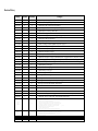
Revision History
Date(s)
Version
Revision(s)
6 JUN 2012
8
C
•
Updated the price in Appendix A (footnote 5).
Changes
5 JUN 2012
8
B
•
Minor wordsmithing (mostly) plus a “product name” correction.
5 JUN 2012
8
A
•
Updated prices and “pruned” this revision history.
3 JUN 2012
7
Z
•
Updated logo, revision, release date, prices, and copyright notice.
16 SEP 2010
7
Y
•
Updated preface, Scott King, AH6KL (SK).
6 FEB 2010
7
X
•
Minor tweaks to page 1.
26 JAN 2010
7
W
•
Improvements to page 10 (K2 manual page 28) suggested by AL7B.
17 JAN 2010
7
V
•
Updated prices and copyright notices.
14 DEC 2009
7
U
•
Updated prices & product names.
6 OCT 2009
7
T
•
A minor “wording” tweak and updated retail prices on page 2.
9 AUG 2009
7
S
•
Updated our retail prices on page 2.
6 APR 2009
7
R
•
Updated our retail prices on page 2.
23 MAR 2009
7
Q
•
Updated our retail prices on page 2.
21 MAR 2009
7
P
•
Added step to insert UN-KAF2/KDSP2 header for Control board resistance checks.
9 JAN 2009
7
O
•
Updated our retail prices on page 2; updated Elecraft Inc. copyright notices for 2009; minor tweaks.
6 JAN 2009
7
N
•
Updated copyright date (on cover page) and retail prices and other minor tweaks (on page 2).
16 SEP 2008
7
M
•
Updated Ken’s QTH on the cover page and deleted our printed Headers User’s Guide from page 2.
29 JUN 2008
7
L
•
Updated retail prices on page 2.
9 FEB 2008
7
K
•
Updated Elecraft Inc. copyright notices to cover 2008.
30 JAN 2008
7
J
•
Updated retail prices on page 2.
20 JAN 2008
7
I
•
Minor cover page tweaks.
16 DEC 2007
7
H
•
Minor typo correction in Appendix A.
28 NOV 2007
7
G
•
Minor grammatical corrections and tweaks.
27 SEP 2007
7
F
•
Minor typo correction and updated retail prices on page 2.
17 AUG 2007
7
E
•
Minor typo correction and readability improvements.
13 AUG 2007
7
D
•
Tweaked the document subtitle.
5 AUG 2007
7
C
•
Changed the document subtitle to include mention of the rev. F Elecraft ® K2 manual.
20 MAR 2007
7
B
•
Minor readability tweaks.
22 FEB 2007
7
A
•
A correction affecting K2 manual page 56. Do install RF-D1 as instructed per the Elecraft® manual.
22 FEB 2007
7
–
•
Updated the “How to Use this Guide” section and other minor tweaks.
Re mov ed the beta relea se waterma rk . Ad ded ou r beta tester to the a ck no wledg m ents se ction.
Incorpora ted lots of beta tester su gge stions.
Enla rged the t wo (ne w) spa cer dia gra ms, a dded pa ge nu mb ers.
Yet a nother beta tester su gge stion rega rding the a nnotated footn otes on K2 ma nu al pa ge 60 .
Cha nged ou r sloga n from “ Plu g & Pla y Rea dy” to “ Option Rea d y” to a void confu sing ne wco m ers.
Incorpora ted beta tester feed ba ck a bout the u ninstalled co mp one nts on K2 ma nua l pa ge 70.
Mo ved u p KN B2 sta ndoff insta lla tion, a nd co m pressed the two # 5048 ima ge s (20 0 DPI
9 6 D P I).
Added sta ndo ff loca tions to the a nnotations on K2 ma nual pa ge 71.
Minor twea k s to K2 ma nu al pa ges 70 a nd 71 .
Redu ced the fa ding so bu ilders ca n u se this gu ide to repla ce the a ffected K2 ma nua l pa ges.
Repla ced K2 ma nu al “ errata style” redlining instru ctions with a nnota tion s, a nd a dde d “ beta” wa terma rk.
Added Appen dices – Re quire d Pa rts, An no tated K2 Sc he ma tics, Colo r Code d Un-modu le Diagra m.
Asse m bly procedu re cha nge to install the SSB Front Pa nel parts soon er.
Added “ firm wa re” wa rning a bou t ma king pre-S/N 40 60 K2 s “ Op tion Rea dy” for the K6 0 XV.
15 JAN 200 7
throu gh
17 FEB 200 7
6
A– P
•
•
•
•
•
•
•
•
•
•
18 DEC 200 6
throu gh
14 JAN 200 7
5
A– N
•
•
•
•
AP R 2 0 06 – S E P 2 0 0 6
4
A– F
In co rp o rated su g g est io n s f ro m L U5 O M an d DF 7 TH .
JA N 2 0 0 6 – AP R 2 0 0 6
3
A– P
Of f ic ia lly p u b lish ed ; in co rp o r ated co m m en ts f ro m K G 6 X V T, W 1SR B, L U5 O M , W 7 G H, an d W 3 FPR .
D EC 2 0 0 5 – J A N 2 0 0 6
2
A– K
A lp h a an d b et a test r e le ases w ith su g gest ed im p ro vem en ts f ro m N 8 LP an d K G 6 ZV T.
1 9 D EC 2 0 0 5
1
–
Pre -r e le ase.
- ii -
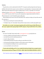
Preface and Acknowledgements
My investigation into the possibility of a rework-free K2 build began in December 2004 after I completed a High Reliability Soldering course at
the local junior college. This was before Ken’s first Reflector post about his prototype UN-PCB headers, so I started by designing some un-modules
using perf-board. In doing so, I noticed an error in the original KE1L article’s description of an UN-KNB2 header. (The value specified for the
resistor on the output leg of the attenuator was off / low by 19 percent.) This was a crucial find since Ken and I would soon offer an un-module kit.
Referring to the table on page 4 (excluding mic configuration jumpers) the electrical differences between a bare and an “Option Ready” K2 are the
absence of six original components and seven jumpers; and the addition of 15 components, two jumpers, and 12 connectors. Un-modules “undo” 14
of these differences while 12 don’t require undoing. The final piece of the rework-free puzzle was provided by Elecraft’s Scott King (SK) who suggested incorporating the K60XV supplied K2 VCO parts, and changing the new Extended VCO Range (D19) menu entry to inform the firmware.
With the introduction of our Rework Eliminator™ brand option bypass header kit, some of our early customers were already using a draft of our
rework-free assembly instructions in late summer 2005. Without the encouragement of those pioneers this guide might never have existed. We are
especially grateful for the contributions of the following Elecrafters, and for Wayne and Eric’s permission to reproduce portions of the K2 manual:
Scott King (SK), Bruce Bowman (NM5B), Doug Shields (W4DAS), Larry Phipps (N8LP), Eric Jorgensen (KE6US), Sverre Holm (LA3ZA), Mitch Easton (W2MDE),
Darrell Bellerive (VA7TO), Bill McCann (K3UJ), Matt Osborn (KC0UKK), Craig Rairdin (NZ0R), Bob Abell (VE3XM), John Crux (G3JAG), Bob Sosin (KD4WNQ),
Ed Muns (W0YK), Jeff Bender (KG6ZVT), Craig Smith (AC0DS), Bob Solosko (W1SRB), Manuel Wilches (LU5OM), Rob Locher (W7GH), Joerg Tack (DF7TH),
Mike Short (AI4NS), Mark Raybould (G3XYS), Bill Fruit (WA9ACP), Chuck Guenther (NI0C), Bob Zinn (N5BZ), Charles Pitts (N3EJS), Alan Wilcox (W3DVX),
Karl-Heinz Kaatz (DF7KHK), Dave Mueller (AA3EE), David Wilburn (K4DGW), Mike Casey (KC9ORD), Mike Weir (VE3WDM) , Dick Mobley (AL7B).
Gary KI4GGX
16 September 2010
Table of Contents
Introduction ................................................................................................................................................................................................................................... 1
Disclaimer...................................................................................................................................................................................................................................... 1
How to Use This Guide ................................................................................................................................................................................................................. 2
What Is An “Option Ready” K2? .................................................................................................................................................................................................. 2
Rework-Free Assembly Summary ................................................................................................................................................................................................ 4
Rework-Free K2 Manual Annotations .......................................................................................................................................................................................... 5
Appendix A – Required K2 PCB Parts ....................................................................................................................................................................................... 23
Appendix B – Annotated K2 Schematics .................................................................................................................................................................................... 25
Appendix C – Color-Coded K2 Un-Module Diagram ................................................................................................................................................................ 32
- iii -
- 1 -
Introduction
This guide describes a rework-free assembly method for the Elecraft® K2. It incorporates un-module option bypass headers and 46 option supplied K2 parts which include electrical components, connectors, miscellaneous wire, and mounting hardware. Our instructions seamlessly combine
initial K2 assembly with the changes that must be made prior to installing the options. The result is an “Option Ready” K2 for which the later
installation of the options is dramatically simplified. When installing the options, there’s no need for significant disassembly or any additional
soldering on the K2’s three main circuit boards. Except for possibly re-jumpering the mic configuration header (behind the Front Panel) for a
different microphone, there’s no need to disassemble the enclosure to add the options.
Other than installing back panel connectors (for the K60XV and K160RX), all that’s required prior to adding any of the options that mount on the
K2’s circuit boards is to:
1. Remove the top cover and the option’s associated un-module header(s).
2. If installing the “analog” or the “advanced digital” auxiliary audio filter, first replace a machine screw with the option supplied hex spacer.
After installation, refer to each option’s instruction manual regarding the possible need for Beat Frequency Oscillator (BFO) and crystal
filter set up, mic configuration header jumpering, Bandpass Filter (BPF) re-alignment, or Voltage-Controlled Oscillator (VCO) re-calibration.
Disclaimer
Our rework-free “Option Ready” alternate assembly method may not be appropriate for everyone, particularly builders who:
• just feel more comfortable exactly following the manufacturer’s assembly instructions.
• want to build the base radio for the absolute minimum (initial) cost.
• do not plan to add any internal options.
• find the annotated K2 manual pages in this guide too confusing or too much additional work to follow.
• have the necessary skills and equipment to perform the rework that’s otherwise necessary to add some options.
• do not mind significantly disassembling the enclosure as required to add most options.
• are not concerned about the resale value of their radio.
If you have already started building your K2, or if you are confused by the instructions in this guide, then we recommend you instead
follow the instructions in the Elecraft® K2 manual. IF YOU HAVE A PRE-S/N 4060 K2, PLEASE READ APPENDICES A & B NOW! ! !
Elecraft’s permission to reproduce portions of their manuals does not constitute an endorsement of our products or rework-free assembly method.
- 2 -
How to Use This Guide
1. Based on which options you are initially getting with your K2 and which options you want to build it “Option Ready” to accept, review Appendix
A to determine which (if any) of our Duplicate K2 PCB Parts Kits will be required.
2. Visit www.unpcbs.com and order our option bypass Headers Kit, plus whichever of our K2 PCB Parts Kits you determined will be required.
3. Print (preferably in color) the 17 annotated K2 manual pages in the section entitled K2 Manual Annotations (which begins on page 5). You may
also wish to print the first five pages of annotated schematics in Appendix B.
4. Being very careful to mark the correct pages, add comments on these 17 pages in your actual Elecraft® K2 manual to instead refer to these 17
annotated manual pages.
5. Build a rework-free and very easily upgradeable K2. In doing so, you will learn far more than you would have using Elecraft' original method.
What Is An “Option Ready” K2?
If you were to build and align your K2 using the instructions in the Elecraft® manual, then rework it’s three main circuit boards to permit
installation of all internal options, but instead of installing any options you just installed un-module bypass headers; and if you also changed the
Extended VFO Range (D19) Secondary menu setting to ‘yes’, then the result would be similar to a “Option Ready” K2!
This is essentially what you get by following the instructions offered in this guide. The main difference is that using our method, the two
procedures – the initial build and alignment, plus the modifications necessary to install every option – are seamlessly combined into a single reworkfree and disassembly-free procedure! There is one other difference. With our method you will have already performed VCO calibration with
Extended VCO Range(D19) set to “yes”, so the subsequent installation of the K60XV option might not require re-adjusting RF-L30.
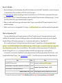
As shown below, you can have this “Option Ready” result by starting out with just a bare K2 and getting duplicates of the 47 K2 parts – which
are supplied with the Elecraft® options – from www.unpcbs.com for $34.35. (You will also require our un-module Option Bypass Headers kit.)
Item
Price
Elecraft® K2 HF Transceiver kit
Notes
$739.95 Given what’s included, the stock K2 is a bargain!
Rework Eliminator™ Option-Ready / Duplicate K2 PCB Parts kits*
$34.35
Rework Eliminator™ Option Bypass Headers kit
$23.50
Discounted “Option Ready” Bundle … $52.00
( Bundle Discount ) Total
$791.95 Excluding shipping & handling, and applicable state sales taxes.
* Not required if purchasing a fully loaded K2. Some (individual) parts kits are required if you are purchasing a partially loaded K2.
- 3 -
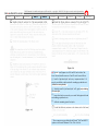
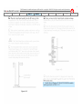
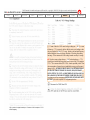
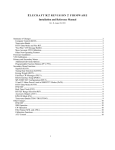
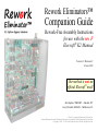
Not included in an
“Option Ready” K2.
This image of #5048 shows three items which
are not part of an “Option Ready” K2: 1) Ken’s
custom brass plate; 2) the “option supplied” hex
spacer which is very easy to install; and 3) RF-J5
(Aux AF) which provides fixed level audio for
digital modes. Although adding J5 requires some
disassembly and additional soldering, it’s not part
of an “Option Ready” K2 because it doesn’t relate
to the installation of an existing Elecraft® option.
The two large white (2-pin) connectors along
the right side of the RF board are P6 (Aux RF) and
P3 (Aux 12V). They are provided with the options
that mount in the top cover. P6 is particularly difficult to install in a completed K2 as it entails removing the heatsink.
Although the Noise Blanker standoff is the only
one required by our un-module headers, all four RF
board mounted standoffs are included in an “Option
Ready” K2 since their later installation requires disassembly of the enclosure, and because (for the
K60XV and K160RX standoffs) this disassembly
involves removing the heatsink.
Additionally, it's quite likely that someone
selling a used option wouldn't bother to
disassemble their radio and remove these spacers
to include them with the option. (In contrast, the
KAF2/KDSP2 provided hex spacer is very simple
to remove, although many KAF2 and KDSP2
"sellers" fail to include it when selling these
options.)
- 4 -
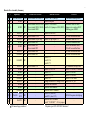
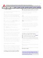
Rework-Free Assembly Summary
#
Option(s)
PCB
DELETED STEPS
17 KAF2 & KDSP2 CTRL Do not install R18 & R19
28
KSB2 FP
-
48
KNB2
RF
50
50
51
51
K60XV
KSB2
K60XV
KNB2
RF
RF
RF
RF
51
KSB2
RF
56
56
K60XV
K160RX
RF
RF
57
K160RX
RF
K60XV
KSB2
KNB2
K60XV
K160RX
K60XV
KSB2
KNB2
K160RX
KAT2
71 KPA100
KBT2
RF
RF
RF
RF
RF
RF
RF
RF
RF
71
RF
57
59
59
59
59
60
71
71
71
K60XV
RF
K2 manual page numbers
ADDED STEPS
Install J1 & J2 (on top)
Install SSB parts
Do not install R88 (470 Ω) Install 2.7 kΩ at R88
Do not install R89 (100 Ω) Install a 0 Ω jumper at R89 (W89)
Do not install R90
Install D19 & D20
Do not install C167
Do not install 82 pF cap
Install 120 pF cap at C71
Do not install W5
Do not install W2
Do not install W3
Do not install W6
Do not install W1
Install C13
Install C14
Install C75
Do not install C6
Install J9, J10, J11
Install J12
Install J13, J15
Install J14
Change Extended VFO Range (D19)*
Install KSB2 standoff
Install KNB2 standoff
Install K160RX standoff
Install P6 (Aux RF)
Install P3 (Aux 12V)
Install K60XV standoff
Install “V RFDET” / J13-6 jumper
NOTES!
Common mounting holes!
Different value for R88!
Jumper wire replaces R89!
Nothing goes at R90!
J11 will be installed later
Different value for C71!
J12will be installed later
J9 will be installed later
J10 will be installed later
J13 will be installed later
J14 will be installed later
J15 installed (on top) later
Install UN-KSB2 (2 headers)
Install UN-KNB2
Install UN-K60XV
Install UN-K160RX
From “no” to “yes”
KPA100 requires both plugs
* Requires post S/N 4059 K2 firmware!
-
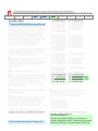
- 5 -
Rework-Free K2 Manual Annotations
KAT2
KBT2
KPA100
KAF2
KDSP2
KNB2
K160RX
K60XV
KSB2
Multiple
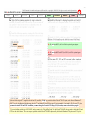
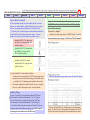
1. The color code above is used on the previous page and all following pages, to indicate for which option(s) an annotation applies. If you
never intend to install some options, this coding makes it easy to select for which options you want your K2 to be “Option Ready”. Please
only attempt this if you are certain how the assembly procedure changes relate to the options. If you are unsure, either request assistance,
build your K2 so it’s “Option Ready” for all options, or use the traditional instructions in the unaltered K2 manual instead.
a) The KIO2 is not included in this color code legend because the base K2 already provides the necessary connector (CTRL-P4) to support
its “Option Ready” installation.
b) Regarding the purple shaded options, it’s possible to build your K2 so it’s only “Option Ready” for just the KAT2 or just the KB2T.
However, to make it “Option Ready” for the KPA100, your K2 needs to be “Option Ready” for both the KAT2 and KB2T.
2. An “Option Ready” K2 means that no additional soldering on it’s three main circuit boards, or significant disassembly of its enclosure are
required to fully load it with options. However, you still must follow the post-installation setup, calibration, and/or alignment instructions in each option’s manual! In addition to installing connectors on the back panel for some options:
a) After installing the SSB option, the Beat Frequency Oscillator (BFO) and crystal filters need to be set up, plus it may be necessary to
change the jumpers on FP-P1, (the mic configuration header) to support your microphone.
b) After installing the 60 Meters & Transverter I/O option, the Voltage Controlled Oscillator (VCO) needs to be checked on the 60 meter
band. As a consequence, it may be necessary to readjust RF-L30 and then realign the VCO as explained on page 61 of the K2 manual.
c) After installing the 160 Meters & Receive Antenna option, the 80/160 meter bandpass filter inductors (RF-L2 and L4) must be realigned.
3. Building your K2 with “Option Ready” support for all options requires that you refer to the individual option manuals when adding some
option supplied parts. Thus for the options that you haven’t yet purchased, you should download their manuals from the Manual
Downloads page on Elecraft’s website.
4. The markups on the following pages are based on the current set of K2 and options manuals as of 18 December 2006. Please refer to the
section “How to Use This Guide” (on page 2) for recommendations on how to best use these annotations. And yes, the fading is intentional.
Elecraft’s permission to reproduce portions of the K2 manual, does not constitute an endorsement of our products or rework-free assembly method!
- 6 -
REW•RK-FREE K2 ASSEMBLY
KAT2
KBT2
The K2 manual is the intellectual property of Elecraft, Inc, copyright © 1999-2012, all rights reserved, used with permission.
KPA100
KAF2
KDSP2
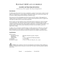
Δ Be sure that the following electrolytic caps – and any other tall parts on the
right side of the CTRL board – are seated flush and standing perfectly vertical.
This will ensure adequate clearance between them and the KAF2 or KDSP2.
KNB2
K160RX
K60XV
KSB2
Multiple
- 7 -
REW•RK-FREE K2 ASSEMBLY
KAT2
KBT2
The K2 manual is the intellectual property of Elecraft, Inc, copyright © 1999-2012, all rights reserved, used with permission.
KPA100
KAF2
KDSP2
KNB2
K160RX
K60XV
KSB2
Multiple
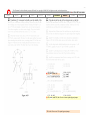
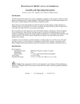
Δ Do not install jumper wires R18 and R19 on the back of the
board. Instead, install connectors J1 and J2 on the front as follows.
[ ] Install a 5-pin female jack* on the top / component side at J1. It
must be seated flush on the board and be standing perpendicular to it.
Solder the center pin only.
[ ] Similarly, install a 3-pin female jack* at J2, again only soldering
the center pin.
[ ] Inspect both jacks to ensure they are seated flush against the board
and standing perpendicular to it.
[ ] Solder the remaining pins of both jacks.
* These connectors are provided with the Elecraft® KAF2 and KDSP2
options or the Rework Eliminator™ Aux Filter Jacks kit.
- 8 -
REW•RK-FREE K2 ASSEMBLY
KAT2
KBT2
The K2 manual is the intellectual property of Elecraft, Inc, copyright © 1999-2012, all rights reserved, used with permission.
KPA100
KAF2
KDSP2
[ ] Install a Rework Eliminator™ UN-KAF2/UN-KDSP2 un-module
option bypass header at CTRL-J1 / J2.
KNB2
K160RX
K60XV
KSB2
Multiple
[ ] Remove the UN-KAF2/UN-KDSP2 header from the CTRL board to
reduce the possibility of damaging it. It will be re-installed again in a
later step for phase I alignment and test.
- 9 -
REW•RK-FREE K2 ASSEMBLY
KAT2
KBT2
The K2 manual is the intellectual property of Elecraft, Inc, copyright © 1999-2012, all rights reserved, used with permission.
KPA100
KAF2
KDSP2
KNB2
K160RX
K60XV
KSB2
Multiple
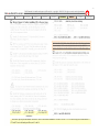
[ ] Skip ahead to the section entitled SSB Components at the top of page
28 and install all of these KSB2 (or Rework Eliminator™ KSB2 Parts kit)
supplied parts now! This includes the installation and configuration of P1.
- 10 -
The K2 manual is the intellectual property of Elecraft, Inc, copyright © 1999-2012, all rights reserved, used with permission.
KAT2
KBT2
KPA100
KAF2
KDSP2
SSB Components
[ ] Install the KSB2 option or Rework Eliminator™ KSB2 Parts
kit supplied Front Panel components* on the front/top of the board
near the cutout for the headphone jack.
__ C4 – C8** (.01 μF)
__ Q3 (2N3906)
__ RP3 (10K, 8 pins)
__ R13 (68.1K, 1%)
[ ] Install P1 (the Microphone Configuration Connector) on the
back/bottom of the board. Insert the shorter pins (tails) into the
board. After soldering one pin, ensure P1 is mounted flush.
Take your time soldering the remaining pins of P1, being careful to
avoid touching and damaging nearby switch S6 with your iron.
[ ] If you have the Rework Eliminator™ Internal Mic Adaptor
(IMA), skip ahead to page 72 and insert a new step to assemble
and install the IMA prior to plugging in the Control board.
Otherwise, review pages 17 and 18 in the Elecraft® KSB2 manual,
and configure FP-P1 for your microphone. (Do this now!)
(Now go back and resume assembly at the bottom of page 23.)
(after FP PCB assembly is completed)
* Once these components are installed, you may wish to check off all
of the steps under the Front Panel Board Components section on the
bottom half of page 16 in the Elecraft® KSB2 manual. If you haven’t
yet purchased the KSB2 option, you can download the manual from
Elecraft’s website, then print out page 16 and keep it with your K2
manual for future reference.
** For C4 through C8, do not use any other .01 μF caps that belong
to the base K2. Instead, be sure use the special 5mm (0.200") lead
spacing caps that came with either the Elecraft® KSB2 option, or the
Rework Eliminator™ KSB2 Parts kit.
KNB2
K160RX
K60XV
REW•RK-FREE K2 ASSEMBLY
KSB2
Multiple
- 11 -
REW•RK-FREE K2 ASSEMBLY
KAT2
KBT2
The K2 manual is the intellectual property of Elecraft, Inc, copyright © 1999-2012, all rights reserved, used with permission.
KPA100
KAF2
KDSP2
KNB2
K160RX
K60XV
KSB2
Multiple
[ ] Install a Rework Eliminator™ UN-KAF2/UN-KDSP2 un-module
option bypass header at CTRL-J1 / J2.
- 12 -
The K2 manual is the intellectual property of Elecraft, Inc, copyright © 1999-2012, all rights reserved, used with permission.
KAT2
KBT2
KPA100
KAF2
KDSP2
KNB2
K160RX
K60XV
REW•RK-FREE K2 ASSEMBLY
KSB2
Multiple
[ ] Remove the UN-KAF2/UN-KDSP2 header from the CTRL board.*
See notes
1, 2, & 3
* It will be re-installed in a later step for phase II alignment and test.
1) Do not install anything at R90.
2) Instead of the original R89, install W89 (i.e. just a bare jumper wire).
3) Instead of the original R88, install the 2.7 kΩ resistor (RED-VIO-RED) provided
with the Elecraft® KNB2 option, or the Rework Eliminator™ KNB2 Parts kit.
- 13 -
The K2 manual is the intellectual property of Elecraft, Inc, copyright © 1999-2012, all rights reserved, used with permission.
KAT2
KBT2
KPA100
KAF2
KDSP2
KNB2
K160RX
K60XV
REW•RK-FREE K2 ASSEMBLY
KSB2
Multiple
__ D19*
__ D20*
* D19 and D20 are provided with the Elecraft® K60XV option, or the
Rework Eliminator™ K60XV Parts kit.
* Older rev. ‘A’ RF boards (supplied with pre-S/N 3000 K2s) do not have mounting locations for these diodes. If you are assembling an older K2 (with a “rev. A” RF board), you should refer to
the K60XV manual to install diodes D19 and D20, (and resistor R29). Unless you have purchased the K60XV, we discourage building a pre-S/N 4060 K2 so it’s “Option Ready” for the K60XV.
- 14 -
REW•RK-FREE K2 ASSEMBLY
KAT2
KBT2
The K2 manual is the intellectual property of Elecraft, Inc, copyright © 1999-2012, all rights reserved, used with permission.
KPA100
KAF2
KDSP2
KNB2
K160RX
K60XV
KSB2
Multiple
Δ Do not install W5, the Noise Blanker option bypass jumper.
See note 1
Δ Do not install W2 and W3, the SSB Crystal Filter option bypass
jumpers.
*
*
1) Instead of the original C71 supplied with the base K2, install the 120 pF cap provided with the Elecraft® K60XV option, or the Rework Eliminator™
K60XV Parts kit. Installation of this alternate value for C71 and diodes D19 and D20 (on page 50) are inseparable, if you install a 120 pF cap at C71, then
you must also install D19 and D20. In addition, you must change the Extended VFO Range (D19) Secondary menu as described on page 60.
* If you are building an older (pre-S/N 3000 K2) and you want it to be “Plug & Play Ready” for the Elecraft® K160RX, then you need to check that C68 and
C153 have the values shown. These two caps are provided with the Elecraft® K160RX option and by the Rework Eliminator™ Replacement RF Caps kit.
- 15 -
The K2 manual is the intellectual property of Elecraft, Inc, copyright © 1999-2012, all rights reserved, used with permission.
KAT2
KBT2
KPA100
KAF2
KDSP2
KNB2
Δ
K160RX
REW•RK-FREE K2 ASSEMBLY
K60XV
KSB2
Do not install W6*.
Δ Do not install W1, the Receive Antenna option bypass jumper.
* W6 is the Transverter I/O option bypass jumper.
Multiple
- 16 -
REW•RK-FREE K2 ASSEMBLY
KAT2
KBT2
__ C75, 470 (471)*
The K2 manual is the intellectual property of Elecraft, Inc, copyright © 1999-2012, all rights reserved, used with permission.
KPA100
KAF2
__ C13, 1200 (122)*
KDSP2
KNB2
K160RX
K60XV
KSB2
Multiple
__ C14, 1200 (122)*
(continued)
* These three caps are provided with the Elecraft® K160RX or the Rework Eliminator™ K160RX Parts kit. C75 is on the left edge of the board near K13.
C13 and C14 are in the band-pass filter, near L3 and L4.
- 17 -
REW•RK-FREE K2 ASSEMBLY
KAT2
KBT2
The K2 manual is the intellectual property of Elecraft, Inc, copyright © 1999-2012, all rights reserved, used with permission.
KPA100
KAF2
KDSP2
KNB2
K160RX
K60XV
KSB2
Multiple
[ ] Install RF-J9 through RF-J15 per notes 1 through 4 below, right.
[ ] Skip ahead to the section entitled Option Module Standoffs at the
top of page 71, and install just the KNB2 standoff now!
[ ] Install option bypass headers at CTRL-J1 & J2, and RF-J9 through
RF-J15. Except for the UN-J9/J10, the text on all other headers on the
RF board should be right-side up when viewing the K2 from the front.
Secure the UN-KNB2 with a 4-40 × ¼" machine screw.
1) Install J9*, J10*, & J11* per the steps on page 13 of the Elecraft® KSB2 manual.
2) Install J12* per the steps at the top of page 6 in the Elecraft® KNB2 manual.
3) Install J13* & J15* per the steps on page 7 of the Elecraft® K60XV manual.
4) Install J14* per the steps at the top of page 6 in the Elecraft® K160RX manual.
* Provided with the associated Elecraft® option or Rework Eliminator™ K2 PCB Parts kit.
- 18 -
The K2 manual is the intellectual property of Elecraft, Inc, copyright © 1999-2012, all rights reserved, used with permission.
KAT2
KBT2
KPA100
KAF2
KDSP2
KNB2
K160RX
K60XV
REW•RK-FREE K2 ASSEMBLY
KSB2
Multiple
[ ] Change the Extended VFO Range (D19) Secondary Menu to Y*.
* This informs the firmware that you installed a 120 pF cap at RF-C71 (instead of the original 82 pF) and installed RF-D19 and D20, as described on pages 50 and 51.
[
[
[
[
]
]
]
]
Access the Secondary menu by first tapping M E N U and then tapping D I S P L A Y … S E C will be displayed.
Find the D 1 9 entry either by tapping B A N D + or by rotating the main tuning VFO knob.
To change the value, first hold E D I T for at least ½ second. After releasing E D I T use B A N D + to set it Y (meaning, “yes” D19 is installed).
Tap M E N U twice to exit. You must keep this change permanently! Factory reset will undo it, so you must change it back to Y if you ever do a reset!
- 19 -
REW•RK-FREE K2 ASSEMBLY
KAT2
KBT2
The K2 manual is the intellectual property of Elecraft, Inc, copyright © 1999-2012, all rights reserved, used with permission.
KPA100
KAF2
KDSP2
KNB2
K160RX
K60XV
KSB2
Multiple
[ ] If some of the above VCO control voltage readings are < 1.0 V, or some
of them are > 7.5 V, you may be able to shift the entire set of readings so that
they are all within the 1.0 to 7.5 V range. Switch to the band (and frequency)
that had the highest or lowest voltage, then adjust L30 to bring that reading
into range. Then re-measure all of the voltages to make sure they're in range.
Δ If you have some voltages that are < 1.0 V and others that are > 7.5 V,
you may have installed the wrong value at one or more of the VCO capacitors
(C71 - C74) or varactor diodes (D21 - D26). Another possibility is that T5 has
the wrong number of turns or that you installed the wrong type of slug-tuned
inductor at L30. ALTHOUGH MOST LIKELY YOU EITHER FORGOT
TO CHANGE THE EXTENDED VFO RANGE (D19) SECONDARY
MENU SETTING TO “YES” (AS DESCRIBED ON PAGE 60), OR YOU
DID A HARD FACTORY RESET WHICH UNDID THIS CHANGE! If
you change any of these components OR THE (D19) SECONDARY MENU
SETTING, you need to repeat the VCO alignment procedure.
- 20 -
The K2 manual is the intellectual property of Elecraft, Inc, copyright © 1999-2012, all rights reserved, used with permission.
KAT2
KBT2
KPA100
KAF2
KDSP2
KNB2
K160RX
K60XV
REW•RK-FREE K2 ASSEMBLY
KSB2
Multiple
See note 1
1) In order to protect them from physical damage during subsequent
assembly, temporarily remove all Rework Eliminator™ option bypass
headers from both the RF and CTRL boards.
- 21 -
The K2 manual is the intellectual property of Elecraft, Inc, copyright © 1999-2012, all rights reserved, used with permission.
KAT2
KBT2
KPA100
KAF2
KDSP2
KNB2
K160RX
K60XV
REW•RK-FREE K2 ASSEMBLY
KSB2
Multiple
[ ] Check off the components listed below, verifying that they are not
installed. All of these components are on the top side of the board.
Note: P6 and P3 will be installed on the next page. The remaining parts
will not be installed.
__ W1 the RX Antenna Bypass jumper (behind the finals) is replaced by
the UN-K160RX header.
__ W6 the Transverter Bypass jumper (behind and to the left of the driver
Q6) is replaced by the UN-K60XV header.
__ C167 (behind J11) is replaced with the UN-J11 UN-KSB2 header.
__ W2 and W3, the crystal filter bypass jumpers. (See note 1.)
__ W5 the Noise Blanker Bypass jumper (in front of Q22). (See note 2.)
__ R90 (forward from W5). (See note 2.)
1) Jumpers W2 and W3 (near J9 and J10 respectively) are both replaced
by the UN-J9/10 UN-KSB2 header.
2) The UN-KNB2 header replaces W5 and the attenuator originally
formed by R88 (now 2.7k), R89 (now W89), and R90 (not installed).
- 22 -
REW•RK-FREE K2 ASSEMBLY
KAT2
KBT2
The K2 manual is the intellectual property of Elecraft, Inc, copyright © 1999-2012, all rights reserved, used with permission.
KPA100
KAF2
KDSP2
KNB2
K160RX
K60XV
KSB2
Multiple
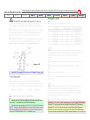
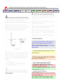
Option Module Standoffs
The three aluminum and the one nylon standoff and their associated
hardware, are supplied with the individual Elecraft® options, and also
with the corresponding Rework Eliminator™ K2 PCB parts kits.
[ ] Referring to the assembly diagrams, install aluminum standoffs for
the following three RF board mounted options using a ¼" (6 mm)
machine screw, and the specified number of split lock washers.
___ Install the KSB2 3/8" (9.5mm) stand-
Transverter Jumper*
[ ] Install a coax cable jumper between V RFDET and J13-6 per the
instructions and picture on page 9 of the Elecraft® K60XV manual.
off (left of J9), using a total of three
split lock washers.
___ Install the KNB2 3/8" (9.5mm) standoff (behind J12), using a total of
three split lock washers.
___ Install the K160RX 5/8" (16mm)
standoff (left of J14), using just two
split lock washers.
[ ] Install the K60XV’s nylon standoff as follows.
___ Remove the nut securing Q6, the (TO-220 style package) driver
transistor, but leave the associated securing screw and lock washer.
___ Install the 9/16" (14 mm) long nylon standoff in place of this
nut using the original screw and lock washer. Do not over tighten
the screw, as this could strip the spacer’s soft nylon threads.
[ ] Re-install all un-module bypass headers on the RF and CTRL boards.
Auxiliary Plugs
The Aux 12V plug (P3) is provided with the Elecraft® KBT2 and
KPA100 options, or the Rework Eliminator™ Aux 12V Plug kit.
The Aux RF plug (P6) is provided with the Elecraft® KAT2 and
KPA100 options, or the Rework Eliminator™ Aux RF Plug kit.
[ ] Install and solder 2-pin male connectors at P6 and P3 so they are
oriented as shown by their silkscreen outlines, i.e. with their plastic
polarizing tabs toward the front of the RF board.
* This step calls for RG174 coax, solid hookup wire, and heat-shrink
tubing. The Elecraft® K60XV option and Rework Eliminator™ K60XV
Parts kit provide more than enough of these miscellaneous wire items.
- 23 -
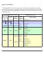
Appendix A – Required K2 PCB Parts
The following table lists all of the parts – electrical components, connectors, miscellaneous wire, and mounting hardware – required to make
current K2s “Option Ready” for each option. It also shows how to obtain these parts, either from Elecraft® options or from our parts kits. In addition
to the color-coded portion of the table, please read the footnotes for all of the options you aren’t getting with your K2, but which you still want it to
be “Option Ready” to accept.
“Option Ready”
Support for This
Elecraft® Option
KIO2 1
KAT2
KPA100 2
KBT2
Requires Either of These Kits
Elecraft®
K2
KPA100
KAT2
KBT2
Rework
Eliminator™
Aux RF Plug
Aux 12V Plug
KAF2 or KDSP2 3
KAF2 or KDSP2
Aux Filter Jacks
KNB2
KNB2
KNB2 Parts
Updated Caps
K160RX 4
K160RX
K160RX Parts
Which Supply These K2 PCB Parts
Reference
Designator(s)
CTRL-P4
RF-P6
RF-P3
CTRL-J1
CTRL-J2
RF-J12
RF-R88
RF-C68
RF-C153
RF-J14
RF-C75
RF-C13, C14
(continued)
(Quantity) / Description
2×5 pin DIP plug
2-pin .156" plug
2-pin .156" plug
5-pin SIP jack
3-pin SIP jack
8-pin SIP jack
2.7 kΩ, 5%, ¼ W
3/8" Aluminum standoff
Machine screw
(3) Lock washer
10 pF NPO
68 pF NPO
16-pin SIP jack
470 pF NPO ("471")
(2) 1200 pF NPO ("122")
5/8" Aluminum standoff
Machine screw
(2) Lock washer
- 24 -
“Option Ready”
Support for This
Elecraft® Option
1
Requires Either of These Kits
Elecraft®
Rework
Eliminator™
K60XV 5
K60XV
K60XV Parts
KSB2
KSB2
KSB2 Parts
Which Supply These K2 PCB Parts
Reference
Designator(s)
RF-C71
RF-D19, D20
RF-J13
RF-J15
RF-J9, J10
RF-J11
FP-Rbias
FP-C4 – C8
FP-P1
FP-Q3
FP-R13
FP-RP3
-
(Quantity) / Description
120 pF
(2) MV209
8-pin SIP jack
3-pin SIP jack
9/16" Nylon standoff
2' RG174 coax
6" #24 Solid hookup wire
3" Heat-shrink tubing
(2) 3-pin SIP jack
12-pin SIP jack
10 kΩ, 5%, ¼ W
(5) .01 uF 0.2" (5 mm)
2×8 pin DIP plug
2N3906
68.1 kΩ, 1%, ¼ W
10 kΩ × 4 resistor network
3/8" Aluminum standoff
Machine screw
(3) Lock washer
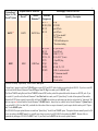
A stock K2 is already “Option Ready” for the Elecraft® KIO2 option.
2
“Option Ready” support for the Elecraft® KPA100 option requires RF-P6 and RF-P3, both of which are provided with the KPA100. If you have a stock K2,
you will need both the Rework Eliminator™ Aux RF Plug and Aux 12V Plug kits to make your K2 KPA100 “ready”.
3
The Elecraft® KAF2 (analog filter) and Elecraft® KDSP2 (advanced DSP) auxiliary audio filter options both include the same two K2 PCB jacks. If you
have a stock K2, you will need the Rework Eliminator™ Aux Filter Jacks kit to make your K2 “Option Ready” for either of these optional filter modules.
4
Beyond the K2 PCB parts required for current K2s, the Elecraft® K160RX also includes two replacement caps which are only needed for “older model” K2s.
These two caps are not included with the Rework Eliminator™ K160RX Parts kit. Instead, they are available via the Rework Eliminator™ Updated Caps kit.
If your un-built K2’s S/N is less than 3060, you should check the values of these two caps to determine if you also require this kit to make your K2 “Option
Ready” for the K160RX option.
5
Pre-S/N 4060 K2s require updated firmware to make them “Option Ready” for the Elecraft® K60XV option. This updated firmware normally retails for $54,
however (according to the K60XV manual), it is available at no charge to owners of pre-S/N 4060 K2s who purchase the K60XV. Because of this, we
recommend only making pre-S/N 4060 K2s K60XV “ready” if you already have the K60XV and the necessary updated firmware.
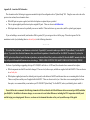
- 25 -
Appendix B – Annotated K2 Schematics
The schematics on the following six pages are annotated to depict the configuration of an “Option Ready” K2. Using the same color code as the
previous two sections, these schematics show …
• Which K2 parts are option supplied, and with which option or options they are provided.
• The six option supplied parts that must replace original K2 parts. These are shown in bold blue font.
• Which parts must be removed or preferably were never installed. These include one cap, one resistor, and five option bypass jumpers.
If you are building a current model (serial number 4060 or greater) K2, you can ignore the rest of this page. Please also ignore all of the
annotations in italic font (including those in red italic font) in the following schematics.
--- - - - ---
It is critical that you know your firmware revision level. Especially if you want to make a pre-4060 K2 “Option Ready” for the K60XV
option. If you don’t have the latest firmware, then you will need to purchase it from Elecraft, Inc. for $54.00! In contrast, if you buy the
K60XV option from Elecraft and at the time of purchase you inform Elecraft that you have an older K2, then the K60XV manual states that
they will provide the updated firmware at no extra charge. THIS IS LIKE GETTING THE K60XV FOR LESS THAN HALF PRICE!
For those of you building or upgrading older (pre-S/N 3000) K2s with the rev. A RF board, the schematics have comments that explain …
• Which components in older K2s need to be changed. There are two, both are caps, and both are supplied with the K160RX. These are shown
in red italic font.
• Which option supplied parts must be soldered (point-to-point) on the bottom of the RF board because there are no mounting holes for them.
There are only three and they are all supplied with the K60XV. These are shown in italic font. Since there are no mounting holes for these
three parts, we recommend that you not make a pre-S/N 3000 K2 “Option Ready” for the K60XV, unless you definitely plan to install it.
Even with the above comments, the following schematics still do not describe all of the differences between current (post 4059) and older
(pre-4060) K2s. In addition to firmware changes, we are aware of several other differences, including the PLL temperature stability mod
and the keying wave-shaping mod. However, we choose not to document them here as they are beyond the scope of this guide.
- 26 -
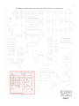
The K2 schematics are the intellectual property of Elecraft, Inc, copyright © 1999-2012, all rights reserved, used with permission.
- 27 -
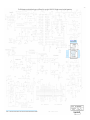
The K2 schematics are the intellectual property of Elecraft, Inc, copyright © 1999-2012, all rights reserved, used with permission.
J1 & J2 supplied
with KAF2 & KDSP2.
Appendix B
- 28 -
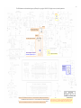
The K2 schematics are the intellectual property of Elecraft, Inc, copyright © 1999-2012, all rights reserved, used with permission.
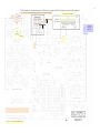
(NOTE 5)
(NOTE 4)
R29 supplied with all K2s since
S/N 3000, and with the K60XV.
(NOTE 2)
D19 & D20 supplied with K60XV.
C71
120
The K2’s original C71 is replaced
with K60XV supplied 120 pF C71.
C75 supplied with K160RX.
P3 supplied
with KBT2
& KPA100.
NOTE 2: Pre-S/N 3000 K2s (those with the earlier rev. A RF board) don’t have mounting holes for D19 and D20.
NOTE 4: Pre-S/N 3000 K2s (those with the earlier rev. A RF board) don’t have mounting holes for R29.
NOTE 5: C68 is 10 pF in current K2s. It is included with the K160RX because older
K2s used a different value. It is not included with the Rework Eliminator™ K160RX
Parts kit, but is provided with the Rework Eliminator™ Replacement RF Caps kit.
- 29 -
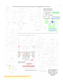
The K2 schematics are the intellectual property of Elecraft, Inc, copyright © 1999-2012, all rights reserved, used with permission.
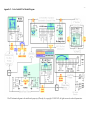
J12 is supplied with the KNB2.
The K2’s original R89 is replaced
with W89, a zero ohm jumper wire.
W89
0Ω
2.7 k
The K2’s original R88 is replaced
with KNB2 supplied 2.7 k R88.
(NOTE 1)
NOTE 1: J9, J10, and J11 are supplied with the KSB2.
(NOTE 3)
NOTE 3: C153 is 68 pF in current K2s. It is included with the K160RX, because older K2s used a different value It is not included
with the Rework Eliminator™ K160RX Parts kit, but is provided with the Rework Eliminator™ Replacement RF Caps kit.
- 30 -
The K2 schematics are the intellectual property of Elecraft, Inc, copyright © 1999-2012, all rights reserved, used with permission.
J14 is supplied with the K160RX.
⌂
J15, J13, and the RG174 coax cable for jumpering V RFDET to J13-6, are supplied with the K60XV.
V RFDET
P6 supplied
with KAT2
& KPA100.
(NOTE 3)
NOTE 3: C13 & C14 are supplied with the K160RX.
- 31 -
The K2 schematics are the intellectual property of Elecraft, Inc, copyright © 1999-2012, all rights reserved, used with permission.
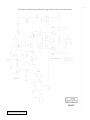
All components shown on RF Sheet 4 are provided with the K2.
- 32 -
Appendix C – Color-Coded K2 Un-Module Diagram
The K2 schematic diagram is the intellectual property of Elecraft, Inc, copyright © 1999-2012, all rights reserved, used with permission.