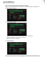
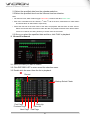
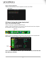
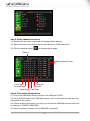
1
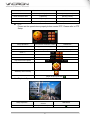
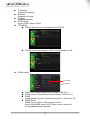
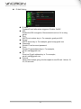
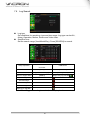
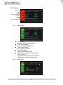
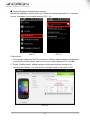
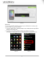
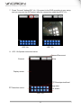
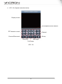
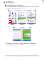
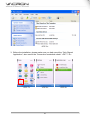
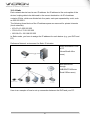
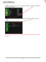
4CH H.264 Digital Video Recorder USER MANUAL 2013 APR V1.2 optional WARNING Do not expose the DVR under the sunlight, heat or wet environment while installation. As it could decrease the performance of DVR and damage the machine. Do not touch the power plug or case with wet hands as this could result electric shock. Do not forcedly bend or put heavy object on power cable as this could result in injury to personal or equipment. Do not operate with damaged power cord or loose electrical outlet as this could result in electric shock or accident. Please use individual power instead of share electrical outlets with other electrical equipment as this could result in damage or accident. Do not attempt to service this DVR by yourself as it may expose you to dangerous voltage or other hazards. Please refer all service to the qualified servicing distributor. Do not open the covers or insert any object into DVR. CAUTION Do not place the machine on an uneven surface or it would decrease the DVR efficiency or malfunction. Avoid any shock or bumping of the DVR while recording. Improper handling could damage the system. CAUTION Make sure the voltage selector switch is set to appropriate setting before plug in! ii CONTENTS 1. 2. 3. 4. 5. 6. 7. 8. 9. 10. 11. 12. 13. 14. 15. 16. Specification ............................................................................................. 1 Structure of Product .................................................................................. 2 DVR Installation ........................................................................................ 4 System Operation ..................................................................................... 4 Display Setup ........................................................................................... 7 Search ...................................................................................................... 9 Main Menu .............................................................................................. 11 7.1 Camera Setup ................................................................................ 11 7.2 Record Setup ................................................................................. 13 7.3 Alarm Setup ................................................................................... 16 7.4 Motion Detection ............................................................................ 16 7.5 Network Setup................................................................................ 17 7.6 Log Search ..................................................................................... 20 7.7 Backup ........................................................................................... 21 7.8 System ........................................................................................... 22 7.8.1 Time Setting ......................................................................... 22 7.8.2 HDD Setup ........................................................................... 22 7.8.3 Display Setting ..................................................................... 24 7.8.4 System Information .............................................................. 25 7.8.5 User Password ..................................................................... 25 7.8.6 System Language ................................................................ 26 7.8.7 Audio Setting ........................................................................ 26 7.8.8 System Maintenance............................................................ 26 Cell Phone Monitoring Operation............................................................ 28 H264 Player Operation ........................................................................... 49 H264 HDPlayer Operation ...................................................................... 51 Web Operation ....................................................................................... 53 Appendix ................................................................................................ 61 12.1 How to search and playback the footage step-by-step? ................. 61 12.2 How to backup the footage step-by-step?....................................... 64 12.3 How to setup the Network step by step?......................................... 66 12.3.1 Static ..................................................................................... 67 12.3.2 DHCP ................................................................................... 72 12.3.3 PPPoE .................................................................................. 77 12.3.4 How to set up a 3G connection for your DVR? ..................... 79 12.4 Email Setup .................................................................................... 80 12.5 DDNS Setup ................................................................................... 81 Default Setting ........................................................................................ 87 HDD Support List.................................................................................... 88 Operation System For Mobile Phone Application ................................... 89 3G Data Rate.......................................................................................... 89 iii 1. Specification Video System NTSC PAL Operating System Embedded Linux VGA Output D-SUB 15P VGA Video Input 4 x (1Vp-p 75R) BNC Audio Input 4 x RCA(CH1~CH4) Video Output 1 x (Monitor Out) BNC Audio Output 1 x RCA OSD Interface GUI interface / Multi-Language (English / Traditional Chinese / Others) Display Frame 240 fields/s (4x60 fields/s) 200 fields/s (4x50 fields/s) Recording Frame 30fps (CIF/HD1/D1) / 20fps(1.5D1) 25fps (CIF/HD1/D1) / 16fps(1.5D1) Playback Frame 30fps (CIF/HD1/D1) / 20fps(1.5D1) 25fps (CIF/HD1/D1) / 16fps(1.5D1) Display Mode Pentaplex Mode Display Resolution Recording Single / Quad / Auto Switch Recording / Playback / Network / Mobile Phone Surveillance 720x480 720x576 360x240 @CIF 360x288 @CIF 720x240 @HD1 720x288 @HD1 720x480 @D1 720x576 @D1 960x480 @1.5D1 960x576 @1.5D1 Compression Format HDD Management H.264 SATA HDD x 1 (No HDD Included) Backup Device Searching Host USB 2.0 Mode Time/Date, Event Full Screen Yes Alarm Input / Output 4 x Input / 1 x Output Key / LED 17 Keys (Max.) / 2 LEDs Motion Detection(MD) Yes Video Loss Detection Yes Switching Yes Buzzer Yes Brightness Setting Yes Contrast Yes XGA Output Adjustable, 1440p x 900p (max.) HD Output 1080p30 / 720p60 Mouse Yes (USB 2.0) P/T/Z Control Pelco-D / Pelco-P ( RS-485) Watchdog Network Auto Power Recovery H.264 (STATIC,DHCP,PPPoE) Mobile Phone Windows Mobile / Symbian / iPhone / Android / Blackberry Power supply DC 12V / 3A (AC100V~240V 50/60HZ) Dimension 315mm x 222mm x 68mm (W x D x H) Operating Temperature 0℃~ 46℃ 1 2. Structure of Product Front Panel Power Indicator HDD Indicator The LED lights on when power on. The LED lights on when the HDD is written. Channel 1 Under the live viewing mode / playback mode channel 1 display. Channel 2 Under the live viewing mode / playback mode channel 2 display. Channel 3 Under the live viewing mode / playback mode channel 3 display. Channel 4 Under the live viewing mode / playback mode channel 4 display. Quad Under the live viewing mode / playback mode Quad display. Under the live viewing mode, press MENU to enter the main menu. Menu Under the menu mode, press MENU to go to the upper menu. Fast Rewind Playback: x2 / x4 / x8 / x16 / x32 Multiple Speed. Fast Forward Playback: x2 / x4 / x8 / x16 / x32 Multiple Speed. Slow Forward Playback: 1/2 Step Pause Play Manual Record Stop Up Down Left / 1/4 / 1/8 Multiple Speed. Under the playback mode, press Step button to enter Play Frame by Frame mode. Under the playback mode, press the button to pause the playback. Under the live viewing mode, press the Play button to enter the playback mode. Press this button to start recording in live mode. Under the playback mode, press the button to stop the operation or go to upper menu. To move up of the selection setting in menu. To move down of the selection setting in menu. To move left of the selection setting in menu. Right To move right of the selection setting in menu. Enter Press the Enter button to confirm the setup or go into sub-menu. USB 2.0 Port USB Backup or Firmware Update. 2 Installation 1 Video In 1-4 CH Video Input (BNC) 2 Audio In 1-4 CH Audio Input 3 Video Out 1CH Video Output (BNC) 4 Audio Out 1CH Audio Output (RCA) 5 LAN 6 USB Mouse Port 7 Alarm I/O 8 XGA 9 HD Output 10 E-SATA Support external storage system and the Port Multipliers function 11 RS-485 For Speed Dome Use 12 DC12V Power Input RJ-45 Network Connection 2.0 USB Mouse Alarm In/Out PC Monitor Output 1080p/ 720p resolution Output Alarm I/O Item Point 1: CH1 sensor input. Point 2: CH2 sensor input. Point 3: CH3 sensor input. Point 4: CH4 sensor input. Point 5: ground. Point 6: the first relay joint port. Point 7: the first relay normal open. 3 3. DVR Installation Connect the camera video output to the DVR video input port with BNC connectors. The camera install coaxial cable is suggested cat 6 or above. DVR Network installation Please connect DVR to HUB or router by using RJ-45 network cable and make sure the DVR network indicator LED is on. (Please refer to Network Setup for further network setting information of using static IP, PPPoE or DHCP. ) Alarm Installation Please refer to Installation for external alarm I/O installation. Please refer to Alarm Setup. Speed Dome Installation This device can support 3 kinds of communication protocol (Pelco D, Pelco P & MIKAMI) Power Installation Please use the provided power cable and adaptor to connect the DVR (AC100V~AC240V). Please refer to Installation for connecting position. The DVR system will enter into live viewing mode when power is connected. Please refer to Display Setup - Live Viewing Mode for more information. 4. System Operation There are 3 kinds of DVR control method: front panel, remote control and USB mouse. USB Mouse Operation 1. Quick Menu: Right click the mouse button under the live viewing mode to go for enter into Quick Menu. 2. Left click the mouse button under the main menu to go to the sub-select menu. 3. Left click the mouse button under the select menu to go to the sub-menu. 4. Use the mouse to change the setting. 5. Please refer to Display Setup - PTZ Setup. Remote Control Operation Remote Control and front panel operation are the same; please refer to Front Panel and the reference table of the button as below. 4 CH2 display CH1 display Record CH3 display CH4 display Mute Quad display Menu Navigator Enter Fast Rewind Fast Forward Play Stop/ Remote ID Setup Step/Pause 5 Virtual Keyboard Operation The text input of the virtual keyboard is as below: Front Panel & Remote Menu Operation Mouse Operation Control Operation Select character from virtual keyboard [Up/Down/Left/Right] [Move Cursor] Keyin the select character [Enter] [Left Click] Exit the virtual keyboard [MENU] [Left Click]out of selection area Key Description of Virtual Keyboard Delete the previous character Switch to text input Enter key. Save and exit the virtual keyboard Other Keys Character Keyin Main Menu Operation Main menu Setup Operation Front Panel & Remote Control USB Mouse Select [Up/Down/Left/Right] [Moving Cursor] Enter Select Menu [Enter] [Left Click] Setup Operation Setup 6 Setup Operation Front Panel & Remote Control USB Mouse Select [Up/Down/Left/Right] [Moving Cursor] Confirm Select Setting [Enter] [Left Click] Change the Select Setting [Left/Right] [Left Click] 5. Display Setup There are 3 kinds of screen display mode: Live, Auto Switching and PTZ. DVR. Live Viewing Mode The DVR will go to the live viewing mode after boot up. There are 5 different status icon: ●: Record M: Motion Triggered L: Video Loss A: Alarm Triggered : Sound on/off Setup Operation Front Panel&Remote Control Channel 1~4 Single Channel Display [CH1~4] 4 Channel Split Display [4 CH Split] Quick Menu [MENU] [Right] Playback Mode [Play] [Right] QuickMenu Start/Stop the Manual Record [Record] [Right] QuickMenu Start/Stop the Auto Switching Front Panel [Auto Switch] Remote Control [Auto Switch] [Right] QuickMenu Start/Stop Mute Remote Control [Mute] [Left] Left Click USB Mouse Select one of channel [Double click left button] Under single channel [Double click left button] Quick Menu Main Menu Remote Lock PIP Search PTZ Back Up Manual REC Info 7 Zoom Mode Auto Switching Setup Operation Front Panel & Remote Control USB Mouse Select Item [Left/Right] [Moving Cursor] Enter the Select Item [Up/Down] [Moving Cursor] Confirm the Select Item [Enter] [Left Click] Exit [MENU] [Left Click] out of selection area PTZ Please set the speed dome properly before control PTZ. Please refer to PTZ Setup. Setup Operation Front Panel & Remote Control USB Mouse Select Item [Up/Down/Left/Right] [Moving Cursor] Enter Select Item [Enter] [Left Click] Zoom +,Focus, +Iris, +Adjust Movement Speed PTZ Up / Down / Left / Right Start/Stop Auto Tracking Exit [Right click] or [Left click ] Playback Operation Setup Operation Front Panel & Remote Control Fast Rewind [Fast Rewind] 8 USB Mouse Fast Forward [Fast Forward] Step Forward [StepForward] Step/Pause [Step/Pause] Play 1x [Play] Stop [Stop] Digital Zoon None Drag by Left Click Derived Image None [Left click] 1~4 Single Channel Display [1~4 Channel] Select Channel [Double left click] 4 split Display [4 split] Under single channel [Double left click] Auto Switching 1. Auto switch starts from order CH1~CH4, 4 split channel. 2. Press the button again to stop the function. 6. Search In Live mode, use Play button in the front panel/remote controller or right clicking the mouse to switch to the Search function. Setup Operation Front Panel & Remote Controller USB Mouse Search [Enter] [Left Click] Select Channel [Up/Down] [Moving Cursor] Select Dates [Up/Down/Left/Right] [Moving Cursor] Playback [Enter] [Left Click] Return to Upper Menu [MENU] [Right click] or [Left click ] No data: no color, data of alarm trigger: red color, normal record data: green color. Select the first half of hour frame under the date, the playback will start from 00 mins: 00 sec. Select the second half of hour frame under the date, the playback will start from 30mins:00sec. If there is no data on the date, please try to search from record list. 9 Select any of 4 channels to playback. Record List Enter Select Item Front Panel & Remote Controller [Enter] Select Item [Up/Down/Left/Right] Return to Upper Menu [MENU] Setup Operation USB Mouse [Left Click] [Moving Cursor] [Right click] or [Left click ] First Page Previous Page Next Page Last Page Mark all the events in this page BackUp List all of recording data and click on one of record data to playback. Backup Please click “BACKUP” to backup the selecting file to USB memory stick. 10 7. Main Menu Camera Record Sensor Motion Network Log Search Back Up System Setup Operation Front Panel & Remote Controller USB Mouse Select Item [Up/Down/Left/Right] [Moving Cursor] Enter Select Item [Enter] [Left Click] Exit Main Menu [MENU] [Right click] or [Left click ] 7.1 Camera Setup Channel Select one channel to set. Use CopyButton to copy present settings to other channels. Camera Title Set the title of camera. Key in by using virtual keyboard. Title Position Set the title position. Set: Top Left, Top Right, Bottom Left, Bottom Right and Off. Display Display the channel, set: On/Off Camera Color Setup 11 Hue: 0~50 Brightness: 0~50 Contrast: 0~50 Saturation: 0~50 PTZ Setting Type Speed dome model type. Set: PTC-301, PTC-203ST, FUM 626, JG_QG988, FUM 622SD, FUM 628 or off. Please select the correct communication protocol if you enable this setting. Protocol Speed dome protocol. Set: PELCO P, PELCO D, MIKAMI or off. Address Speed dome address. Set: 0~255 Baud Rate Speed dome baud rate. Set: 1200, 2400, 4800, 9600, 19200. Tilt Opposite Set speed dome image upside down. Set: On/Off Preset Front Panel & Setup Operation Remote Controller USB Mouse Select Item [Up/Down/Left/Right] [Moving Cursor] Enter Select Item [Enter] [Left Click] Zoom +,Focus +,Iris +,Adjust Move Speed Set PTZ Up/Down/Left/Right Start/Stop Auto Tracking Number Preset Setting This function is preset 95 enter the menu 12 Save Preset Setting Clear Preset Setting Clear All Preset Setting Return to Upper Menu [Right click] or [Left click ] Buzzer Duration The buzzer ON duration when video loss. Alarm Relay Duration The Relay ON duration when video loss. Time Display Display the time in LIVE mode. Values: ON/OFF. 7.2 Record Setup Record Enable Setup On/Off the channel. Watermark: Insert the words of watermark. Resolution Setup NTSC Recording Resolution: 720x480 / 720x240 / 360x240 / 960x480. PAL Recording Resolution: 720x576 / 720x288 / 360x288 / 960x576. 13 Frame Rate Setup Setting of Frame Rate: NTSC: 0-30 frames/sec; PAL: 0-25 frames/sec. Quality Setup Setting of recording quality: Values 1-5. The bigger value, the better quality. Pre Record setting Pre Recording time when motion alarm. Values: 0-10 seconds. 14 Privacy Zone Select channel for privacy mask setup. Channel: Select channel to setup. Press『COPY』 to copy the same setting to other channels. Enable: Enable/Disable the privacy mask function. Color: Select the color of privacy mask area setting in color Gray/Black/White/Red/Green/Bule/Yellow/Purple. Privacy Zone: Set the privacy mask area. Audio On/Off the sound effects. Encode Mode Encoding of channel. Values: VBR or CBR. Record schedule setup Always and Schedule Record. Record Schedule Schedule Setup Operation Front Panel & Remote Controller USB Mouse Enter Select Item [Enter] [Left Click] Select Channel [Up/Down] [Moving mouse wheel] Select Time&Date [Up/Down/Left/Right] [Click/Drag-draw] Return to Upper Menu [MENU] [Right Click] or [Left Click Copy (1) Select source (2) Select target (3) Press COPY icon to copy. 15 ] 7.3 Alarm Setup Channel Select the channel to set. COPY icon can copy the present setting to other channels. Sensor Mode Sensor Mode alarm trigger. Set: OFF / NO / NC. Relay Mode Relay Mode alarm trigger. Set: NO / NC Record Duration The duration of the recording after triggered: 10, 20… 60 sec. Buzzer Duration The duration of the buzzer beeping after being triggered: 1, 5, 10, 15, 20, 30 sec. Alarm Duration Alarm out after alarm triggered: 1, 5, 10, 15, 20, 30 sec. Event Popup The Duration of single channel display after being triggered: 1, 5, 10, 15, 20 sec or off. 7.4 Motion Detection Channel Select the channel to set. COPY icon can copy the present setting to other channels. Enable Enable/disable motion detection for each camera. Set: On/Off Sensitivity Sensitivity level of motion detection. Set: 1~10. Higher value equal more sensitive. 16 Motion Area Setup Setup by each small square. Setup Operation Front Panel & Remote Controller USB Mouse Area Selection [Up/Down/Left/Right] [Moving Cursor] (1)Move to the area (2)Press Enter to set the area [Drag by Left Click] (1)Move to the area (2)Press Enter to set the area [Drag by Left Click] [MENU] [Right Click] Set Detection Area: must set on none detection area(Transparent Area) Clear Detection Area: clear the set detection area: must set on detection area(Green Area) Return to Upper Menu Record Duration The duration of the recording after triggered: 10, 20… 60 sec. or off. Buzzer Duration The duration of the buzzer beeping after being triggered: 1, 5, 10, 15, 20, 30 sec. Alarm Duration Alarm out after alarm triggered: 1, 5, 10, 15, 20, 30 sec. Event Popup The Duration of single channel display after being triggered: 1, 5, 10, 15, 20 sec or off. 7.5 Network Setup Mode Set the connection method. Set: Static IP, DHCP, PPPoE. Media Port Port used for stream media. Default is port 9000. WEB Port Port used for web access. Default is port 80. Command Port Port used for settings. Default is port 8000. Mobile Port Mobile phone port (factory default): 15961. 17 IP Address Assigned IP address. Netmask Assigned net mask Gateway Assigned gateway HOST Name Set the HOST Name of DVR. PPPOE/3G PPPoE: Need account and password for PPPoE. 3G: Need account, password, APN and dial number for 3G. DDNS setting HOST NAME DVR NAME DNS1 First Domain Name Server, Default : 168.95.1.1 DNS2 Second Domain Name Server, Default :168.95.192.1 DDNS Enable/disable Dynamic Domain Name server. Values: On, Off. DDNS Server DDNS Server, Values: 3322, dyndns, cctvdvr. When using DDNS server, HOST name, server name and account/password are required. 18 E-Mail Setting E-MAIL Forward E-mail after alarm triggered. Enable: On/Off SSL Enable the SSL encryption. Recommend to set on if it is using gmail. Port SMTP port number key in. For example, gmail port 465. Server SMTP server key in. For example, gmail: smtp.gmail.com Password Sender E-mail account password From Sender E-mail address key in. For example, gmail: [email protected] To Receiver E-mail address key in. For example, gmail: [email protected] Interval When alarm keeps going, the time span to send E-mail. Values: 10, 30, 60 seconds. 19 7.6 Log Search Log type Set conditions for searching: type and time range. Log type can be ALL, Alarm, Operation, Motion, Sensor and Video Loss. Start/End time Set the search range (Year/Month/Day). Press [SEARCH] to search. Setup Operation Front Panel & Remote Controller USB Mouse Enter Select Item [Enter] [Left Click] Select Item [Up/Down/Left/Right] [Moving Cursor] Return to Upper Menu [MENU] [Right click] or [Left click First Page Previous Page Next Page Last Page Backup to USB disk ★ When Trigger Recording is marked, click to playback. 20 ] 7.7 Backup Channel Backup all channels or single channel 1-4. Record Type Select all, normal or alarm. Start/End time Select the backup range of time. Press Search to start searching. The record list will be shown if available and follow [Record list] to backup. Storage Device Choose: USB Disk, DVD Recorder, USB DVD Recorder. 21 7.8 System Time Setup HDD Display System Information Password Language Audio System Maintenance 7.8.1 7.8.2 Time Setting Date/Time Select by using virtual keyboard. Date Format Setup Set: YY/MM/DD, MM/DD/YY. Time Format Setup Set: 24Hours, 12Hours. Time Zone Setup Time Zone setting of DVR. NTP Setting(Network Time Protocol) NTP: On or Off Schedule Time: Using virtual keyboard NTP server: Using virtual keyboard HDD Setup 22 Format Format the selected HDD Format HDD Overwrite Enable/Disable Overwrite, Values: On/Off. If Overwrite is enabled, the period can be set as 6, 12, 24, 36, 48, 72 hours and 7, 15, 30, 60 days. Pack Time Set the required packing time frame to allow the system to pack each saving file under continue recording mode. Pack time setting: 5 min, 10min, 15min, 20min, 30min, and 60min. HDD Error Buzzer Enable When the hard drive does not have enough space or something wrong, set the buzzer on. Values: On/Off. HDD Error Alarm Enable When the hard drive does not have enough space or something wrong, trigger the alarm. Values: On/Off. USB Disk Info Format USB Memory Stick 23 7.8.3 Display Setting GUI Display GUI display mode can be VIDEO or VGA. Video Switching Time Set the switching time when switching channels in video mode. Values: 1-99 seconds. (0 sec is Off) VGA Switching Time Set the switching time when switching channels in VGA mode. Values: 1-99 seconds. (0 sec is Off) Switching Sequence Set the switching sequence of channels. Video Margin Set the display margins of the screen. They are Left, Right, Top and Bottom with range between 0 - 36. XGA Resolution XGA Resolution: 800x600, 1024x768, 1280x1024, 1440x900. 24 7.8.4 System Information Provide the firmware version, MAC address, HDD status…. 7.8.5 User Password Password Setup Enable/Disable password checking. Values: On/Off (Default) Administrator account/password can not be blank. And at least 4 characters for the password. Administrator account/password Administrator account allows user to access all of functions. User account/password Access rights can be assigned by setting. Remote ID setup Can adjust remote control ID to control multiple DVR. 25 7.8.6 7.8.7 7.8.8 System Language Language Values: Traditional Chinese and English. Auto rebooting after change. Function Tip Show function tips below the menu items. Value: On/Off (Default). Audio Setting Audio Volume Set the volume of audio In/Out. Values: 1-10. (Default: 5) System Maintenance Auto maintenance: Set time for auto rebooting. Value: On/Off. Auto rebooting setting 26 F/W update Please plug the USB memory stick into the USB port on the DVR rear panel after download the new firmware to the USB memory stick. Note: the firmware only can be upgraded by using the USB port. Please don’t operate the system, remove the USB memory stick or remove the power while it is in upgrade progressing in order to prevent any serious system error. The system will automatic reboot after upgrade. Load Setup Default Load factory default. Refer to [Default Setting]. Reboot the DVR Reboot the DVR. ShutDown System will close the recording file. Please remove the power line manually. 27 8. Cell Phone Monitoring Operation JAVA Script surveillance: 1. The mobile Phone must support JAVA Script 2. To download the JAVA software: open Internet Browser on the mobile phone, and enter the IP address of the DVR and add /viewer.jar at the end. Example: http://xx.xxx.xxx/viewer.jar. 3. Execute the application 4. Click on “Add” on the drop down menu to add an IP address. 5. Enter the IP address, user name 6. Enter the correct IP address and and the password of the DVR and click click on “Open” on “Save” 7. Click on “Connect” to connect to the 8. Connecting DVR. 10. If fail to connect, please repeat steps 7 to 9. 9. Connected Menu Capture Channel[1~4] 28 ■ Android Software install/setup procedure Before the installation, please check the ”Allow Non-market application” or “unknown source” checkbox in your mobile phone< PIC 1~2>. <PIC 1> < PIC 2> First method 1. First, please make sure the PC synchronize software had installed and activated in your Android mobile phone. And connect your android phone to PC via USB. 2. Install “Castillo player” software player to the Android phone through your synchronize software. You may see the example below in the case of HTC. <PIC 3> 29 <PIC 4> Method two You may copy the APK installation package to your mobile phone or memory card, and then install it through other software. 1. Copy the “Castillo player” software package to your mobile phone through USB or directly to SD memory card. 2. Download the free APK installation software from Market, for example APKinstallerc or AppInstaller, here we use AppInstaller for example<PIC 5~6>. <PIC 5> <PIC 6> 30 3. Run the AppInstaller program, install the APK software package from your SD memory card<PIC 7~8>. <PIC 7> <PIC 8> 4. After the installation, you may find the “Castillo Player” in your program list, click it to run the program<PIC 9>. <PIC 9> 31 5. Press the “Setup” button to setup the connection setting <PIC 10>. Enter your individual configuration<PIC 11>. <PIC 10> <PIC 11> 6. After setting complete, enter a name you prefer then click the “Add to my favorite” checkbox to save the setting<PIC 12~13>. <PIC 12> <PIC 13> 32 7. Press “Connect” button<PIC 14>, it’ll connect to the DVR according to your setup, and you may see the DVR picture after the connection established<PIC 15>. <PIC 14> <PIC 15> 8. <PIC 16>Operate instruction below: Connect/Disconnect Set up Channel Display screen PTZ Zoom/aperture/focal Snap shot PTZ direction control Full screen <PIC 16> 33 ■ iPhone software install/setup procedure 1. Download the “Castillo player” in AppStore then install it to your IPhone. <PIC 1~6> <PIC 1> <PIC 4> <PIC 2> <PIC 5> 34 <PIC 3> <PIC 6> 2. Run the “Castillo Player” after installation<PIC 7>. Press “setup” button to setup the connection setting<PIC 8>. Enter your individual configuration then press “back” button to go back to the main screen<PIC 9>. <PIC 7> <PIC 8> <PIC 9> 3. Press “Play” button, then you may see the DVR live view picture after the connection established <PIC 10~11>. <PIC 10> <PIC 11> 35 4. <PIC 12> Operate instruction below: Display screen Zoom/aperture/focal distance PTZ direction control Channel Connect/Disconnect Set up Snap shot Next page Full screen <PIC 12> 36 ■ Symbian Software install/setup procedure 1. Copy the Symbian player to your mobile phone or memory card; you may see the example below in the case of NOKIA. <PIC 1~5> <PIC 1> <PIC 2> <PIC 4> <PIC 3> <PIC 5> 2. Connect the mobile phone to PC via USB, copy the live view software to the memory card of your mobile phone <PIC 6>. 37 <PIC 6> 3. Before the installation, please make sure you had cancel the “Only Signed Application”, also cancel the “Connection credentials check” <PIC 7~11>. <PIC 7> <PIC 8> 38 <PIC 9> <PIC 10> <PIC 11> 4. Enter the folder which you’d saved the live view software “fuho_20110221.sisx”, double click to install, follow the instruction to proceed <PIC 12~22>. <PIC 12> <PIC 13> <PIC 14> <PIC 15> <PIC 16> <PIC 17> 39 <PIC 18> <PIC 19> <PIC 20> <PIC 21> <PIC 22> 5. After the installation, enter the “Installed Application” and you may see the “Castillo Player” inside <PIC 23~25>. <PIC 23> <PIC 24> 40 <PIC 25> 6. Click and run the Castillo Player program <PIC 26~27>. <PIC 26> <PIC 27> 7. Press the “Setup” button to setup the connection setting. After setting complete, click the “Add to my favorite” button to save the setting. Press “Connect” button, it’ll connect to the DVR according to your setup <PIC 28~32>. <PIC 28> <PIC 29> 41 <PIC 30> <PIC 31> <PIC 32> 8. <PIC 33>Operate instruction below: Display Screen PTZ direction control Zoom/ Aperture/ Focal distance Channel Connect / Disconnect Exit Full screen Snapshot Add to Set up Next page <PIC 33> 42 ■ Windows Mobile Software install/setup procedure 1. Please install “Microsoft ActiveSync” into the PC before installing CAB software. 2. Execute the Microsoft ActiveSync program in your PC first, and connect the Windows Mobile SmartPhone to PC via USB, then it’ll synchronize the SmartPhone and PC. 3. In ActiveSync program, Click “Browse” button to open the mobile device folder <PIC 1>. <PIC 1> 4. Copy the .CAB file of Castillo Player to your mobile device folder, or any other folder according to your individual needs <PIC 2>. <PIC 2> 43 5. Please disconnect the SmartPhone from your PC, and begin the installation below: 6. Execute the Castillo Player CAB install package from the File browser, you may find it in your mobile device folder <PIC 3~5>. <PIC 3> <PIC 4> <PIC 5> 7. Double click and it’ll begin the installation, follow the instruction for setting up. After the installation, you may find the “Castillo Player” in your program <PIC 6~10>. <PIC 6> <PIC 7> 44 <PIC 8> <PIC 9> <PIC 10> 8. Run the Castillo Player program, press the “Setup” button to setup the connection setting. After setting complete, enter a name you prefer then click the “Add to my favorite” checkbox to save the setting. Press OK and Leave to go back to the main screen <PIC 11~14>. <PIC 11> <PIC 12> 45 <PIC 13> <PIC 14> 9. Press “Connect” button, it’ll connect to the DVR according to your setup, and you may see the DVR picture after the connection established <PIC 15~16>. <PIC 15> <PIC 16> 46 10. <PIC 17>Operate instruction below: Channel Connect/Disconnect Display screen PTZ direction Control snapshot Zoom/aperture/focal distance <PIC 17> 47 1. Blackberry Software Connect Procedure Blackberry RTSP Connect procedure: Verify Authentication, website address input format as below rtsp://(website address)/ch(channel number)?user=(user ID)&pwd=(user password) e.g. rtsp://f16.cctvdvr.com.tw:554/ch2?user=2222&pwd=2222 2. Mobile Webpage: Please enter the ID & password again after you login, or you’ll get black screen of permission denied as below: 48 9. H264 Player Operation Preface H264 Player software allows to playback the backup saving file from the DVR. System Requirement Operating System: Windows 2000, XP, Vista, Windows 7. Program obtainment and installation While user start to backup the file from DVR, the system will automatically copy the H264Player.exe file and recorded data to the backup device for example, an USB flash memory stick. Execute the installation file Step 1: Ask for the Installation Step 2: Select the Install Location Step 3: Select Additional Tasks Step4: Install Confirmation Step 5: Installation Complete 49 User Interface Open File Click Pause Click Stop Click Play 1x Click Fast Forward Click Slow Forward Click Capture the image (snap shot) to the host computer Click Volume Control Drag Rewind Click Step Forward Click Mark start time Click Mark end time Click Backup Click Right click the mouse to open the Pop-up Menu pop-up menu including Setting, Language, About H264Player, Exit 50 10. H264 HDPlayer Operation Preface H264 HD Player supports direct HDD playback through USB connection. It also supports to playback the individual recorded video files. System Requirement Operating System: Windows 2000, XP, Vista, Windows 7. Execute the installation file Step 1: Ask for the Installation Step 2: Select the Install Location Step 3: Select Additional Tasks Step4: Install Confirmation Step 5: Installation Complete 51 User Interface Event Search Backup Player Snapshot Step Volume Control Fast Play 9 Win Slow Play Stop Pause Play Open Disk Open File 4 Win 1 Win Backup Mark Out Mark In Pop-up Menu Right click the mouse to open the pop-up menu including Setting 52 11. Web Operation Preface The Web Application Manager allows the user to remotely monitoring, playback, and backup through the DVR. System Requirement Operating System: Windows 2000, XP, Vista, Windows 7 Web Browser: Internet Explorer Add-on Installation Please use the IE browser to login the IP address of DVR setting. If the user is the first time to login the page, the system will ask the user to download and install the add-on as you can see the page below. Please click the request to install the ActiveX add-on. User Interface Login Page Please login user name and password from the setting of DVR end. 53 Live mode Start/Stop the Live Monitoring Record the Footage to Computer Snapshot the Image Enable/Disable Audio Click Click Start recording or (saving path: Setup/Information) Click to snap shot the image (saving path: Setup/Information) Click under the live viewing mode to enable the audio, and click Volume Control Switch Channel Display Single/4 Display Stop recording to disable Click Double click the channel to enter single channel display, double click again to return. Click Speed Dome Preset Point PTZ Control Please refer “PTZ” for more information 54 Playback (1) Select Date Event Search (2)Click or (3)Click Playback Click on pop up file list Fast Forward Click “Fast Forward” (Speed: 2X, Rewind Click “ Rewind” (Speed: 1/2, 1/ 4X, 1/ 8X, 1/ 16X) Step Forward Click “Previous”or “Step” Snapshot Click Mark start time Click Mark end time Click Backup Click Backup 4X, 8X, 16X) to capture. Click “Backup”, backup path: Setup System Setting Backup Location 55 DVR Setting Cameras Please refer “Camera Setup” for more information Record Please refer “Record Setup” for more information. Alarm 56 Please refer “Alarm Setup” for more information. MotionDetection Please refer “Motion Detection” for more information. Network setting E-MAIL 57 Log search System Setting Date/Time Setting HDD Management 58 Display System Information Account/password 59 Audio Setting System Maintenance Host setting 60 12. Appendix This appendix will show you how to do the basic operation step-by-step on search, playback, backup, network setup, email setup, and DDNS setup. 12.1 How to search and playback the footage step-by-step? Step 1. Press the SEARCH button There are two ways to enter the search menu. Option 1: If you are using the front panel or remote control, please press the “Play” button to enter the search menu. Play Play Option 2: If you are using USB Mouse, please click right button of the mouse to open the quick menu bar, and press the “Search” option from the quick menu bar to enter the search menu. Searc 61 Step 2. Select the date & time to playback the footage. Once you enter the search menu, you can have 3 optional selections to playback the footage as the picture below. 1. Date and Time Search 1.1 Select the channel and type of event that you wish to playback. 1.2 Enter the date & time that you wish to search. 1.3 Click PLAY button to playback. 2. Calendar Search 62 2.1 Select the specified date from the calendar selection, 2.2 Select the specified time from the 24hours time bar selection. Note: No data: NO color; data of alarm trigger: Red color; normal record data: Green color st Each hour is divided into 2 time frames, 1 and 2 nd half of the hour, 00min:00sec to 30min:00sec and 30min:00sec to 60min:00sec respectively. Select the first half of the time frame of the date, the playback will start from 00 mins: 00 sec. Select the second half of hour frame under the date, the playback will start from 30mins:00sec. if there is no data on the date, please try to search from the record list. 2.3 Once you select the specified date and time, click PLAY to playback 3. Record List Search 3.1 Select the date you wish to search. 3.2 Click RECORD LIST to enter record list selection menu. 3.3 Double click the event from the list to playback. Record Backup Select Check First Page Previous Page Next Page Back Up Select All Last Page 63 Step 3. Channel Selection. Check on the channels you wish to playback, and then click PLAY. 12.2 How to backup the footage step-by-step? Step 1. Click the BACKUP button There are two ways to enter the BACKUP menu. Option 1: Click the right button of the mouse to open the quick menu bar, and press the “BACKUP” option to enter the search menu. Back Up Option 2: Click the right button of the mouse to open the quick menu bar and select MAIN MENU. Press the “Backup” option from the main menu. Back Step 2. Specify the desired channels, type, start date and time, and end date and time, then press SEARCH. 64 Step 3. Select channels to backup. 3.1 Double click the event to preview the footage before backup. 3.2 Select the events you wish to backup by marking on “BAK” check box. 3.4 Click the backup button to storage device page. Record Backup Select Check First Page Previous Page Next Page Back Up Select All Last Page Step 4. Choose the storage device. 4.1 Plug in the USB flash memory stick into the USB port of DVR. 4.2 Once the DVR detects the USB flash memory stick, it will show the data size and free space on the screen. 4.3 If there is lack of free space, you may try to format the USB flash memory stick first by clicking on FORMAT USB DISK 4.4 Once everything is ready, click on BACKUP to proceed. 65 Step 5. Start Backup the file. Once you click the “BACKUP” button, the DVR will start to backup. When the processing bar reaches to 100%, the backup process is completed. 12.3 How to setup the Network step by step? Decide your network environment In Network setting, you can choose the connection type from Static, DHCP, or PPPoE(which allow you to dial up by ADSL modem or 3G dongle). Below is an explanation of how you can configure your DVR to fit your network environment. 66 12.3.1 Static Each network device has its own IP address. An IP address is like a doorplate of the device, helping data to be delivered to the correct destination. An IPv4 address contains 32 bits, which are divided into four parts, each part separated by a dot, such as 255.255.255.0. The following three blocks of the IP address space are reserved for private Internets (local networks): • 10.0.0.0~10.255.255.255 • 172.16.0.0~172.31.255.255 • 192.168.0.0~192.168.255.255 In Static mode, you have to assign the IP address for each device (e.g. your DVR and PC) Reference Network environment for Static IP situation Direct connection: DVR to PC (Home/Small office users) Multi-connection through HUB/SWITCH/Router (Small Office users) Here is an example of how to set up connection between the DVR and your PC. 67 Step 1: Set your DVR network mode to static mode 1. Change the connection type to “STATIC” in DVR’s network setting 2. Assign the IP address to the DVR Note: Be sure not to set up a duplicated IP address for the DVR. For example, if you assign 192.168.0.100 to the PC, please change the IP address of the DVR to 192.168.0.101 3. Set the Netmask of the DVR: setting. 4. Set the Gateway of the DVR: setting. The address must be the same as the PC’s The address must be the same as the PC’s Step 2: Modify your PC’s network setting to correspond to the DVR For WINDOWS XP: StartControl Panel Network and Internet ConnectionsNetwork Connections Find your network adaptor and click the right button and choose “Properties” 68 Find “Internet Protocol (TCP/IP)” and click the “Properties” to enter the setting menu In the following menu, choose “Use the following IP address” to set up IP address manually 1 2 3 1) Enter the IP address for your PC. Be sure not to set up a duplicated IP address with any other network devices. 2) Enter Subnet mask address. This address should correspond to the Netmask address of your DVR. 3) Enter Default gateway address. This address should correspond to the Gateway address of your DVR. 69 For WINDOW 7 StartControl PanelView network status and tasksclick and enter the next menu Click “Change adapter settings” at the left column 70 Find the network adapter and right click the mouse button and click the “Properties” to enter the setting menu Find Internet Protocol Version 4(TCP/IPv4) and click “Properties” In the following menu, choose “Use the following IP address” to set up IP address manually 71 1 2 3 1) Enter the IP address for your PC. Be sure not to set up a duplicated IP address with any other network devices. 2) Enter Subnet mask address. This address should correspond to the Netmask address of your DVR. 3) Enter Default gateway address. This address should correspond to the Gateway address of your DVR. 12.3.2 DHCP DHCP (Dynamic Host Configuration Protocol) automatically assigns a valid IP address to a network device on the Internet. Allocating a fixed IP address for each device will result in idle IP addresses when the devices are not in operation. Therefore, DHCP can make more efficient use of the IP addresses. To use this feature, you have to have a PC or router to be set as DHCP server to provide the service. Reference Network environment for DHCP situation DHCP connection through Router (Home/small office) 72 DHCP connection through Router/Server (Corporation) Here is an example of how to set up connection between the DVR and your PC in DHCP mode Step 1: Set up your router/DHCP server. or check the manual of the router. For details, please consult your MIS staff DHCP SERVER Setting in DIR-615 (D-Link) Step 2: Set your DVR network mode to DHCP mode 1 ○ 1. Change the connection type to “DHCP” in DVR’s network setting 2. If the router is correctly set, the DVR should be able to get the IP address from the router automatically. Step 3: Modifiy your PC’s network setting to DHCP mode For WINDOWS XP: StartControl Panel Network and Internet ConnectionsNetwork Connections 73 Find your network adaptor and click the right button and choose “Properties” Find “Internet Protocol (TCP/IP)” and click the “Properties” to enter the setting menu In the following menu, choose “Obtain an IP address automatically” 74 For WINDOW 7 StartControl PanelView network status and tasksclick and enter the next menu Click “Change adapter settings” at the left column 75 Find the network adapter and right click the mouse button and click the “Properties” to enter the setting menu Find “Internet Protocol Version 4(TCP/IPv4)” and click “Properties” 76 In the following menu, choose “Obtain an IP address automatically” If the router/DHCP server is set correctly, you should be able to connect to DVR from your PC successfully. Note: The IP address assigned to DVR would be varied when the router restarts or after a period of time. If you want to assign a fixed IP address to the DVR, please check with your MIS staff or the manual of the router. 12.3.3 PPPoE PPPoE (Point-to-Point Protocol over Ethernet) is a protocol that enables connections between a DSL modem and the Internet. This service is provided by ISP (Internet Service Provider). Reference Network environment for PPPoE situation PPPoE connection through Hub/Switch/Router How to set up a PPPoE connection for your DVR? 77 Step 1: In Network setting menu, set the mode to “STATIC” and click the “PPPOE” to enter the setting menu. Step 2: In PPPoE/3G setting menu, set the mode to “PPPoE” and choose “ON” to enable it. Note: for account and password information, please check with your internet service provider. 78 12.3.4 How to set up a 3G connection for your DVR? (Note: for supported USB 3G dongle, please check with the manufacturer for latest information). Step 1: In Network setting menu, set the mode to “STATIC” and click the “PPPOE” to enter the setting menu. Step 2: In PPPoE/3G setting menu, set the mode to “3G” and choose “ON” to enable it. Note: for dial up information, please check with your telecom company for details. 79 12.4 Email Setup In DVR, you can set up an email reminder for situations like motion, alarm, etc. In the following section, we will illustrate how to set it up by using Gmail. Step 1: In Network setting menu, click on “E-MAIL SETUP” and enter the following menu Step 2: Enable the email function by choosing “ON” in E-mail Tab Step 3: ○1 SSL: (Secure Sockets Layer) This is used to secure the internet transmission. For Gmail, you should turn this on. For other email settings, please consult your email service provider. ○2 Port: Default value is 25 and is commonly used for most email server. For Gmail, please set the value to 00465 ○3 Interval: The time interval between each email being sent ○4 Server: your email server. Please noted that this must be your outgoing email server. For Gmail, use smtp.gmail.com ○5 Password: your password for your email address ○6 From: Your email address as the mail sender. In Gmail, it’s like [email protected] ○7 To: The email recipient Note: Not every email server provide the service to relay the email to your email recipient. Please consult your email service provider for more details. 80 12.5 DDNS Setup DDNS: (Dynamic DNS). It is an service to provide the updating in real time of Internet Domain Name System (DNS) name servers to keep up to date the active DNS configuration of their configured hostnames, addresses and other information. In DVR, you can apply a DDNS service for a dynamic IP address. This will help you to use a fixed site address (such as name.idv) to find your DVR so you don’t have to remember the floating IP address (such as 192.168.111.143) To set up the DDNS service, click on “DDNS Setup” in Network setting menu DDNS Setting menu ○1 DNS1&2: This is used for your DNS server. The default value is 168.095.192.001 and 168.095.001.001. If you don’t your DNS server provider, just use the default values for them. ○2 DDNS: To enable the DDNS service. Please select “ON” to enable it. ○3 DDNS SERVER: You can choose DDNS service provider from 3322, dyndns, or cctvdvr ○4 The host name you applied in the DDNS service provider. For example, xxxx.dyndns.org or xxxx.cctvdvr.com.tw ○5 Username: the username you used for DDNS service. ○6 Password: password you used for DDNS service 81 Below we will explain how to apply a DDNS service through Dyndns 1. Go to http://www.dyndns.com 2. Click on Dyndns standard to apply a dyndns account 82 3. Press on “ORDER NOW” to start applying 83 4. Select your wanted Hostname for your DVR Input your wanted hostname for your DVR Note: If you are using firewall or router to connect DVR, please set the DDNS setting in FW/router, then use port forwarding in order to connect 5. When finished, press “Continue” to proceed. 84 6. If you have never applied Dyndns service before, please create a new account first. 7. When finished, press “create account” to proceed. 85 8. System will send you an email for confirmation. Please go to your email box and see if you have received it. There will be a link for you to confirm the application. 9. Go to your DVR to set the DDNS setting. (I use IE for demonstration but in the DVR OSD, you can find the same setting there). 1) Enable your DDNS service. 2) Choose the service to be “dyndns” (depending upon which DDNS provider you use) 3) Input the hostname for the DDNS. (e.g: test.dyndns.org) 4) Input the username for the DDNS. (e.g:[email protected]) NOTE: You might only need to input “test” instead of “[email protected]” depending upon which service provider you use. 5) Input the password for the DDNS Then you can start using the DDNS service for your DVR 86 13. Default Setting Item Default Setting Channel On Resolution Normal Record Frame Rate Real-time Setup Quality Highest Camera Item Audio Disable Schedule Always Channel 1 CH1 HDD Setup Time Setup XGA/Audio Default Setting Overwrite Yes Pack Time 60 Mins Date Format YY/MM/DD Time Format 24 Hours Time Zone GMT+08:00 Daylight Saving Off XGA Resolution 800 X 600 Output Volume 5 Channel 2 CH2 Channel 3 CH3 Input Volume 5 Channel 4 CH4 Mode On Title Position Top Left HDD Loss On Display On Display Time On Setup Setup HDD NO SPACE On Video Loss On 1 sec. Alarm Output 1 sec. Hue 25 Post REC 10 sec. Brightness 25 Buzzer 1 sec. Contrast 25 E-MAIL Off Saturation 25 Switching Time Alarm Setup Camera Color E-MAIL Setup Setup Channel Motion Detection Network Setup DDNS Setup System Maintenance Maintenance Schedule Setup Off Off Type Off Sensitivity 5 Protocol Off Mode Static IP Address 001 Media Port 09000 Baud Rate 9600 Web Port 00080 Tour Time Off IP Address 192.168.000.100 Tilt Opposite Off NetMask 255.255.255.0 Gateway 192.168.000.001 DNS 168.095.001.001 DDNS Off Status PTZ 87 14. HDD Support List Suggest to install the Hard Driver listed below to make sure the compatibility. Brand Model Number Capacity ST3250310CS 250G ST3320410SV 320G ST3500418AS 500G ST3500312CS 500G ST3750528AS 750G ST31000424CS 1T ST31500541AS 1.5T ST32000542AS 2T HCT721025SLA380 250G HCT721032SLA380 320G HCP725050GLA380 500G HCT721010SLA360 1T HDHCT721010LAS360 1T WD3200AVVS 320G WD3200AAKS 320G SEAGATE HITACHI WD5000AVVS 500G WD5000AAKX 500G WD10EURS 1T WD10EVDS 1T WD10EVVS 1T WD15EARS 1.5T WD20EARS 2T WD2001FASS 2T HD502HJ 500GB WD SAMSUNG 88 15. Operation System For Mobile Phone Application O/S Version Mobile Phone Software Android 2.1, 2.2, 2.3 Castillo Player+.apk iPhone 3.x, 4.x CastilloPlayer+ WinMobile 6.5.x CastilloPlayer_5.0.3.CAB Symbian S60 v3 above CastilloPlayer_5.1.713.sisx BlackBerry 16. Support RTSP None Protocol 3G Data Rate Data Transfer Speed (bps) Brand Huawei ZTE Model Support Verified WCDMA (3G) HSDPA HSUPA 2Mbps ~ 386kbps (WCDMA 3.5G) (WCDMA 3.75G) E1550 - 3.6M 384k Yes Pass E160G - 3.6M 384k Yes Pass E1750 - 7.2M 5.76M Yes Pass E220 - 3.6M 384k Yes Pass E156G - 3.6M 384k Yes Pass E173 - 7.2M 5.76M Yes Pass E1820 - 21.6M 5.76M Yes Pass MF626 - 3.6M 384k Yes Pass MF627 - 3.6M 384k Yes Pass MF631 - 7.2M 5.76M Yes Pass MF637 - 7.2M 5.76M Yes Pass MF112 - 7.2M 2M Yes Pass MF180 - 3.6M 384k Yes Pass 89 90