1
OPERATIONS (CONT):
Interfacing Video with Other Systems:
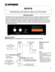
1. VIDEO OUT connection simply passes the composite video signal on to a standard CCTV system, such as a
monitor, input on a switcher, or DVR. This video signal is live as long as the camera is powered. When using this
feature, set the 75 OHM switch to the OFF position.
2. SENSOR input allows a motion detector or other activation device to remotely turn on the camera. Use any device
with a Normally Closed contact. If an audio door station (JF-D/JA-D) is included, the sensor input cannot be used.
3. RELAY connection provides a normally open contact closure that can be connected to an external system. This
can be wired into a record input on a DVR or any other external device that needs to be notified when the video
and audio is activated to the Aiphone monitor.
SPECIFICATIONS:
Power:
Video Input & Output:
Connector:
Audio Door input:
Relay:
Wire:
Wiring distance:
Dimensions:
Supplied by JF/JB Monitor
Composite 1V Peak-to-Peak, NTSC
BNC
Use JF-D/JA-D surface mount door station only
Normally open output, 24VDC, 1Amp
18AWG, 2-conductor, non-shielded, solid or stranded
Max. 330' from JBW-M to Monitor
1-5/8"H x 7"W x 4"D
FCC Class B Verification
NOTE: This equipment has been tested and found to comply with the limits for a
Class B digital device , pursuant to Part 15 of the FCC Rules. These limits are
designed to provide reasonable protection against harmful interference in a
residential installation. This equipment generates, uses, and can radiate radio
frequency energy and, if not installed and used in accordance with the instructions,
may cause harmful interference to radio communications. However, there is no
guarantee that interference will not occur in a particular installation. If this
equipment does cause harmful interference to radio or television reception, which
can be determined by turning the equipment off and on, the user is encouraged to
try and correct the interference by one or more of the following measures:
— Reorient or locate the receiving antenna.
— Increase the separation between the equipment and receiver.
— Connect the equipment into an outlet on a circuit different from that to
which the receiver is connected.
— Consult the dealer or an experienced radio/TV technician for help.
Note:
Only information pertaining to the connection and operation of the JBW-M and devices interfacing
with it are included here. For complete installation, wiring, and operational information about the
JF-2MED or JB-2MD system, please refer to the Installation Manual included with the system.
Aiphone Communication Systems
1700 130th Ave. N.E.
Bellevue, WA 98005
(425) 455-0510
FAX (425) 455-0071
Toll Free Technical Support:
1-800-692-0200
FAX: 1-800-832-3765
E-mail [email protected]
Pg. 3
JBW-M Instr.
0307JD